NATO UNCLASSIFIED
Autonomous Navigation and Mapping in GPS-Denied Environments at Defence R&D Canada Jack Collier, Michael Trentini and Jared Giesbrecht Defence R&D Canada - Suffield PO Box 4000 Station Main Medicine Hat, Alberta, Canada T1A 8K6
[email protected]
Colin McManus, Paul Furgale, Braden Stenning and Tim Barfoot Institute for Aerospace Studies, University of Toronto, Ontario, Canada Stephen Se, Vinay Kotamraju, Piotr Jasiobedzki, Limin Shang, Ben Chan MacDonald Dettwiler and Associates Ltd., Richmond, BC, Canada Adam Harmat, and Inna Sharf Department of Mechanical Engineering, McGill University, Montreal, Canada
ABSTRACT Scientists in the Autonomous Intelligent Systems Section (AISS) at Defence R&D Canada (DRDC) undertake research to enhance the state-of-the-art in autonomous localization, navigation and mapping for unmanned vehicles. Although related work relies on the availability of GPS as part of an integrated navigation system, AISS recognizes that fieldable autonomous military ground and air assets will be required to work in areas where the use of GPS for navigation and localization cannot be guaranteed due to occlusion, indoor operations and signal jamming. Even when GPS is present, its accuracy is often insufficient for unmanned mapping and navigation tasks. Under the Advanced Research Project 12pv, Simultaneous Localization and Mapping (SLAM), researchers are developing alternative technologies for navigation and mapping without GPS. These include a near real-time high-resolution 3D mapping system, a lidar-based visual teach and repeat system, and a multi-sensor place recognition system. Related technologies being developed at DRDC include control and SLAM algorithms for a man-packable quadrotor and vision-based autonomous convoying capabilities. These technologies exploit different sensing modalities and track relevant features from the environment to aid in navigation and mapping. The AISS multi-sensor approach ensures that these systems can be deployed in a myriad of operating environments including nighttime operations. This paper provides an overview of the aforementioned research and how it relates to future Canadian military applications.
1.0 INTRODUCTION Unmanned systems are designed to alleviate the soldier’s burden and remove them from harm. The last 20 years has seen a large increase in research in the military robotics industry with unmanned ground and air vehicles currently deployed in theatre. Unmanned Air Vehicles (UAVs) in particular have widely been
RTO-MP-SET-168
PAPER NBR - 1
NATO UNCLASSIFIED
NATO UNCLASSIFIED
Autonomous Navigation and Mapping in GPS-Denied Environments at Defence R&D Canada adopted and are now used in major missions. Currently most robotic systems rely on the presence of GPS to operate effectively. In order for robots to become more widely accepted, UxVs will be required to work in areas where the use of GPS for navigation and localization cannot be guaranteed due to occlusion, indoor operations and signal jamming. Even when GPS is present, its accuracy is often insufficient for unmanned mapping and navigation tasks. Scientists at Defence R&D Canada, together with their industrial and academic partners, recognize the vulnerability of GPS-based solutions and are working to enhance the stateof-the-art in autonomous localization, navigation and mapping for unmanned vehicles. The paper outlines Defence R&D Canada’s approach to operations in GPS-denied environments. Numerous projects are currently being investigated that will push the state-of-the-art in robot navigation and mapping in GPS-denied environments. These techniques have the potential to impact the way the Canadian Forces conduct operations across numerous domains such as CBRNE detection, convoying, dismounted operations, etc. Research is not directed towards any one platform, but instead emphasis is on a balanced approach across the ground and air domains. The remainder of this paper provides an overview of each of these projects including results where possible.
2.0 MULTISENSOR PLACE RECOGNITION Increased UxV autonomy is largely dependant on advances in mapping and navigation algorithms such as Simultaneous Localization and Mapping (SLAM). SLAM is subject to failure, especially over large areas, due to linearization errors, and improper data associations. To overcome these problems, appearance-based SLAM (ASLAM) decouples the loop closing process from the core SLAM algorithm [1,2]. Here, the loop closing process is essentially a place recognition computer vision task and is not prone to failure resulting from gross errors in the robot pose estimate. Place recognition using visual features such as SIFT and SURF works well under small variations in lighting and orientation, but is prone to failure under large variations. Conversely, lidar sensors are robust to variations in lighting and orientation. In this work, researchers from DRDC and MDA Systems Ltd. seek to combine the strengths of the two sensing modalities to improve the robustness of the place recognition system and create a system that can perform place recognition in both day/night conditions. 2.1 System Description
(a)
(b)
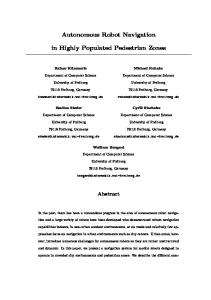
Figure 1 (a) Overview of the multi-sensor place recognition. (b) Urban trial results. Blue - no loop detected, Red - valid loop, Green - false positive rejected by the loop verification algorithm.
PAPER NBR - 2
RTO-MP-SET-168
NATO UNCLASSIFIED
NATO UNCLASSIFIED
Autonomous Navigation and Mapping in GPS-Denied Environments at Defence R&D Canada
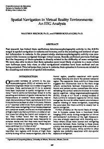
The system developed here is a multi-sensor ASLAM system (Figure 1a) and is an extension of the FABMAP system [3] that uses a generative model based on the bag-of-words approach to achieve large-scale place recognition. Our algorithm runs in parallel for both image-based FAB-MAP (using SIFT features) and rangebased FAB-MAP. To perform recognition on range data, we extend FAB-MAP by incorporating a shape descriptor called the Variable-Dimensional Local Shape Descriptor (VD-LSD) [4]. This descriptor is robust to lighting and orientation and is compact in storage [5]. Separate place recognition results are generated from both sensor streams and integrated to provide a final loop closure result. In the training phase, representative lidar and visual data are input to their respective feature extraction algorithms. Bag-of-words clustering is performed in the VD-LSD and SIFT feature spaces to group features of similarity and create the vocabularies for lidar and visual imagery respectively. During run-time new features are extracted from data. A probabilistic detector model uses the vocabulary generated in the training phase to convert the extracted features into an appearance vector. The booleanvalued appearance vector compactly represents which words in the vocabulary are present in the current scene. These appearance vectors are then compared to those of the previous scenes and a matched is determined using a Bayesian model learnt in the training phase. If a match has been determined, a validation based on the 6-DOF module is used to detect false positive matches and compute the 6-DOF transform between true loops. Both the lidar and the visual imagery results are used by the integration module to obtain the final loop detection result and transform which can be used to perform SLAM loop closing. 2.2 Experimental Results During system trials, a vehicle traversed a large outdoor environment (5.8km), including several loops for portions of the trajectory (Figure 1-right). The vehicle collected stereo imagery (45 degree field-of-view) and 3D lidar data (360 degree field-of-view). With the proposed system we obtained 112 true positive loop detections and zero false positives. While FAB-MAP sometimes reported false positives, they were correctly rejected by our pose verification step. Figure 2a shows an example of a true loop closure, in which the topdown view of the point clouds show that there are more 3D structures in the urban scene, which would facilitate loop detection using lidar data. Further trials were conducted to evaluate the effectiveness of the multi-sensor approach for 24-hour vehicle operation. Over a 12-hour period (0900-2100), the vehicle traversed the same loop of a rural environment collecting data. Using the 1200 test set as the initial loop, we then processed each additional hourly dataset as the second loop. By traversing the same loop we were able to isolate the effect of illumination and easily calculate the recall rate (The percentage of loops detected divided by the true number of loops). Figure 2b shows the hourly place recognition recall rates for video only, lidar only and both video and lidar. As this is a rural environment, the 3D structure is sparse, therefore, the recall rate for lidar is not that high. The visual imagery recall rate is much higher due to the visual feature-rich environment, however, it varies significantly as the illumination changes during the day. When both the stereo and lidar data are integrated we achieve the best results. Under favourable illumination, visual place recognition provides very high recall rate. On the other hand, under adverse lighting conditions, the system still provides an adequate recall rate due to recognition using the lidar data.
RTO-MP-SET-168
PAPER NBR - 3
NATO UNCLASSIFIED
NATO UNCLASSIFIED
Autonomous Navigation and Mapping in GPS-Denied Environments at Defence R&D Canada
(a)
(b)
Figure 2 (a) A example of lidar and video imagery of a detected loop. (b) Recall rates during a 12hour period for imagery only, lidar only and for using both imagery and lidar together.
3.0 VISION-BASED AUTONOMOUS CONVOYING For military operations, autonomous convoys could reduce the number of humans required to deliver supplies, decreasing the chance of casualties. Current systems [6] use drive-by-wire trucks equipped with GPS, data radio, radar and laser rangefinders, and computer vision to enable leader/follower behaviour. As a complementary technology, DRDC Suffield is developing a system that relies solely on video to follow the lead vehicle directly. This system (Figure 3a) does not rely on GPS or communications with the lead vehicle, as both can be electronically jammed. A vision-based approach allows the lead vehicle to be chosen at runtime and is applicable to both large and small robotic vehicles. 3.1 System Description In the current DRDC system, the follower's camera is directed at the lead vehicle through a Graphical User Interface (GUI). A box is drawn around the leader as in Figure 1b. The tracking software then learns to recognize the lead vehicle from this view. After training, the leader vehicle begins driving, and the follower vehicle automatically begins following its path.
(a)
(b)
Figure 3 (a) Autonomous convoying system concept. (b) Graphical User Interface used to train the follower on the lead vehicle. The entire convoy can stop and restart seamlessly as required, with each follower vehicle slowing down and stopping at a set distance behind its leader, maintaining convoy structure as defined at the staging point. In
PAPER NBR - 4
RTO-MP-SET-168
NATO UNCLASSIFIED
NATO UNCLASSIFIED
Autonomous Navigation and Mapping in GPS-Denied Environments at Defence R&D Canada
order to stop the convoy, each of the lead vehicles would simply slow down and come to a stop. The autonomous follower would then be disengaged either directly on the vehicle, or remotely from the command and control vehicle. The follower system developed at DRDC Suffield consists of 3 key components: 1. Computer vision algorithms to recognize and track the leader vehicle in the video stream. 2. A pan/tilt/zoom tracking system to maintain the follower vehicle’s camera on the leader vehicle despite the relative angle or distance between them. 3. A control algorithm to follow the leader’s path as determined from the computer vision system. For visual tracking, a number of algorithms have been tested such as colour tracking, Maximally Stable Extremal Regions, and SIFT. One of the main difficulties encountered involves the changing appearance of the lead vehicle due to vehicle turning, changing lighting conditions, or dust. To improve robustness under these conditions two models of the vehicle are used in tracking. A permanent model is created when the system is trained on the lead vehicle. The second model is learned on the fly as the system moves. In order to maintain long-term stability, the second model is only a “temporary” model with a limited lifespan, and is regularly updated during the progress of the convoy. This allows the recognition software to adapt to changing conditions for the short term (such as a turning vehicle), while remaining anchored by the permanent model. To further increase robustness, SIFT features in the permanent model are also monitored and refined over time. Those features that are transient or short lived most likely belong to the background or to a transient effect present at training time are discarded, while those that are observed stably and repeatedly belong to the vehicle and are most appropriate for use for future recognition. The original and stable SIFT features for the back of one of the robotic vehicles tested are shown in Figure 4. Details of this work can be found in [7].
Figure 4 (a) Original SIFT features used for leader tracking (b) Stable features remaining after vehicle operation. When using computer vision algorithms for tracking, it is necessary to keep the leader vehicle in the follower’s field of view, and it is also necessary to maintain the image of the leader within a certain range of scales for recognition. The pan/tilt/zoom control system for the follower vehicle takes the results from the image recognition stage and uses control and filtering algorithms to maintain this attention, while also providing continuous estimates of the leader’s relative position based on the current pan/tilt angles and the current camera focal length. This system is described in [8]. Finally, with a continuous estimate of the leader’s trajectory, the follower vehicle can follow the leader’s path. The system developed follows at a pre-set following time, rather than a pre-set distance [9]. The benefit of this RTO-MP-SET-168
PAPER NBR - 5
NATO UNCLASSIFIED
NATO UNCLASSIFIED
Autonomous Navigation and Mapping in GPS-Denied Environments at Defence R&D Canada approach is that when a leader vehicle travels more quickly, there is a greater separation between the vehicles. However, when the leader slows down, such as for corners or rough terrain, the separation between the vehicles is reduced, improving convoy cohesiveness and improving the results from the image recognition stage. Although the DRDC leader/follower system is not yet field-ready, early proof-of-concept demonstrations have been conducted on the robotic vehicles successfully demonstrating 3 vehicle vision-based convoys at speeds of about 15 km/hr [9]. Experiments are also planned to test this follower system on a smaller robotic vehicle to function in a dismounted support role.
4.0 THREE DIMENSIONAL REALTIME MAPPING The 3D Real-time Modeler (3DRM) is a prototype mobile mapping system for CBRNE first responders currently being developed. 3DRM operates on board a teleoperated robot and provides situational awareness to the operator (i.e. live images, CBRNE detector data, 3D photorealistic models of visited sites, current robot location). 3DRM builds on the CBRNE Crime Scene Modeler (C2SM) developed by MDA [10]. Multiple C2SM units have been deployed with Canadian police first responder units. 4.1 System Overview The 3DRM (Figure 5a-b) is equipped with four fixed Kinect sensors, a sensor head mounted on a pan and tilt unit, CBRNE detectors, and a remote computer. The Kinect sensors provide RGBD data and operate reliably at distances 0.5 - 5m indoors. The sensor head includes a high-resolution stereo camera, a 3D camera (Asus Xtion) and lights. Xtion, similar to Kinect, operates indoors and up to 5 m; the stereo cameras operate indoor/outdoor and provide accurate data up to 20m. All the imaging sensors are calibrated with respect to the PTU frame and are treated as one single virtual sensor with a very large field-of-view. This enables reliable feature extraction and data association even for environments that lack discriminating visual features. An initial estimate of the 3DRM location is provided from an Optical Odometer, measuring motion of the ground, and refined using SLAM. The Odometer provides accurate data on a wide range of surfaces (both indoor and outdoor) and does not suffer from wheel slippage. The system consists of a four main components: a SLAM frontend; a SLAM backend; a CBRN Data Collector and a User Interface and 3D Viewer.
(a)
(b)
PAPER NBR - 6
RTO-MP-SET-168
NATO UNCLASSIFIED
NATO UNCLASSIFIED
Autonomous Navigation and Mapping in GPS-Denied Environments at Defence R&D Canada
Figure 5 (a) Hardware overview of 3DRM. (b) High level overview of 3DRM sub-systems. The SLAM frontend provides continuous localization and mapping through robust feature extraction and data association, which solves the ego-motion of the sensors, detects loop closures, and builds a pose graph for the SLAM backend. A GPU implementation of the SIFT algorithm is used to match image features in 3D Cartesian space. The SLAM backend improves the global consistency of the pose graph upon loop closure. The Tree-based Network Optimizer (TORO) [11] global relaxation algorithm is used to estimate the position of nodes that best satisfied the loop-closure constraints. TORO works well even with poor initial estimates, can be applied to large data sets that contain millions of constraints, and is extremely efficient. The CBRN data collector interfaces with multiple CBRN detectors and automatically geo-locates the data with the 3D models. The flexible design allows adding and upgrading new CBRN sensors as needed. The 3D viewer receives data generated on board the robot and displays augmented 3D models in a stereoscopic display. The 3D models are constructed during the robot motion through the scene, transferred to the control station, and displayed on the stereoscopic display. The 3D viewer generates meshed and texture mapped models in near real-time for display. At each detected loop closure, the model re-adjusts itself based on the updated pose. The operator may observe the model being created and navigate in 3D space. The path taken by the robot is displayed within the model as shown in Figure 6a.
(a)
(b)
Figure 6 (a) Example of 3D model visualization showing the robot’s path (blue line) and overhead view of the map. (b) A 3DRM model overlaid on a floor plan shows the model consistency. 4.2 Experimental Results The 3DRM system has been tested under a variety of environments and lighting conditions. The largest model constructed by 3DRM so far includes a total of 628 frames collected over 554.4 meters. To verify the global consistency of the 3D model, we overlaid the 3D model on the MDA floor plan (Figure 6b). It can be clearly seen the 2D projection of the 3D model fits the floor plan very well. To quantitatively examine the accuracy of the 3D model, we took multiple measurements between the same features in the 3D model and in the real environment settings (See Table 1). The average error was 1.01% with a maximum error of 1.92%.
RTO-MP-SET-168
PAPER NBR - 7
NATO UNCLASSIFIED
NATO UNCLASSIFIED
Autonomous Navigation and Mapping in GPS-Denied Environments at Defence R&D Canada Table 1 Comparison of measurements Measurement 1 2 3 4 5 6
From laser range finder 7.081m 49.111m 23.311m 52.201m 19.370m 21.008m
From 3D Model 6.97775m 49.5955m 22.8629m 52.2644m 19.3403m 21.3131m
% Error -1.46% -0.99% -1.92% 0.12% -0.15% 1.45%
5.0 LIDAR-BASED VISUAL TEACH AND REPEAT Visual Teach and Repeat (VT&R) is an effective technology for autonomous route repeat in GPS-denied environments. During a teach pass, the vehicle uses a visual sensor to construct a series of maps that are stored in memory. Referencing these archived maps and comparing current views with the previously seen views, the vehicle can retrace the taught route to accomplish the repeat pass. VT&R has many potential applications in the military environment. For instance, teleoperated UGVs operating in urban or indoor areas are prone to failure due to loss in communications. VT&R can alleviate this problem by detecting a comms loss and retracing through the taught map to a point where communications can be reestablished. Stereo cameras have been used effectively for visual teach and repeat driving many kilometers under full autonomy [12]. However, passive visual imagery is susceptible to changes in ambient lighting and can sometimes lead to failure. In this work, a lidar-based VT&R is developed that is not susceptible to changes in ambient lighting and allows nighttime operation. 5.1 System Overview This work presents an appearance-based VT&R system that uses lidar as the primary sensor and bridges the gap between the efficiency of appearance-based techniques and the lighting invariance of 3D laser scanners by applying appearance-based methods to 2D lidar intensity images. These lidar intensity images look nearly identical to a standard grayscale camera images, but with the added benefit of looking the same both in the light and in the dark (Figure 7a). Combined with the azimuth, elevation, and range data, a lidar provides all the necessary appearance and metric information required for motion estimation. This lidar-based VT&R system is a first of its kind and has been validated and tested in a planetary analogue environment, autonomously repeating over 11km in a variety of lighting conditions. During the teach pass, the system builds a topologically connected network of keyframes, which is either added to or begins the creation of a pose graph [13]. For each keyframe, SURF keypoints and descriptors, camera calibration/geometry information, timestamps, and lidar imagery (used for visualization only) are stored by the system. Frame-to-frame transformation matrices and their uncertainties are stored along the edges that connect two keyframes in the pose graph, as well as a match list, which specifies the postRANSAC matching keypoints between the two frames. When repeating a route, the system acquires the appropriate chain of relative transformations from the pose graph (in the order that is specified) and constructs the taught route in the vehicle base frame. Once the path has been built in the vehicle frame, at each timestep, the system performs the following steps for localization: 1. Frame-to-frame visual odometry (VO) - This provides an incremental pose update to achieve a good
PAPER NBR - 8
RTO-MP-SET-168
NATO UNCLASSIFIED
NATO UNCLASSIFIED
Autonomous Navigation and Mapping in GPS-Denied Environments at Defence R&D Canada
guess for the next step of localizing against the nearest keyframe. Keypoint matching is done using a nearest neighbour approach in descriptor space. A bundle adjustment technique provides the final frame-to-frame estimate. Estimation takes place in the nearest keyframe’s reference frame making the approach completely relative. 2. Localization against the map - The system localizes against the nearest keyframe on the pose graph (nearest in a Euclidean sense), using the keypoint matching and outlier rejection methods discussed earlier. This provides a relative transformation estimate between the current camera pose and the nearest keyframe, called the branch. As is done for frame-to-frame VO, the estimation is done in the branch reference frame. After matching against the map, the new estimate is transformed into the vehicle frame for the path tracker. During preliminary testing, it was discovered that simple keyframe-to-keyframe matching was not robust enough to large movements and the algorithm would often fail to localize against the map. To address this problem a sliding local map, similar to [13], that attempts to embed the nearest keyframe with additional information from the surrounding keyframes (i.e., we augmented the closest keyframe with surrounding keypoints) was used. Finally, the bundle adjustment procedure was used to compute the final vehicle pose. 5.2 Experimental Results An 1154m route was taught during sunlit conditions around 7:45 pm and autonomously repeated every 2-3 hours for a total of 10 runs, covering over 11km. The lighting varied from full daylight to full darkness over the course of this experiment and the system was always matching to the full daylight conditions (i.e., the teach pass). The Autonosys LVC0702 lidar was the primary sensor used for the trials. The LVC0702 provides 15-bit intensity information, has a maximum range of approximately 53.5m. For these trials, the lidar was configured to obtain 30 degree vertical field-of-view, 480x360 images at 2Hz. Figure 7 shows a GPS plot of both the teach pass (sunlit conditions) and the first repeat pass (complete darkness), a keypoint matching plot showing frame-to-frame VO matches and map matches, and the lateral tracking error for the entire traverse. For this run, the root-mean-squared (RMS) lateral error was 8.2cm and the route was completed fully autonomously without human intervention. Even in the worst case (run 6), the system was able to repeat the taught route with an autonomy rate of 99.5%, which is a feat that could not be accomplished with a passive sensor under the dramatic lighting changes studied here [14,15].
(a)
(b)
RTO-MP-SET-168
PAPER NBR - 9
NATO UNCLASSIFIED
NATO UNCLASSIFIED
Autonomous Navigation and Mapping in GPS-Denied Environments at Defence R&D Canada
(c)
(d)
Figure 7 (a) Lidar Intensity image. (b) Trial GPS track. (c) Keyframe matches for the VO and map matching sub-systems. (d) lateral tracking error between GPS and the localization system.
6.0 MINI-UAV OVERWATCH DRDC has been investigating the use of small quadrotors to provide situational awareness to the dismounted soldier. To enable this capability, new navigation and control algorithms are being developed that will enable small COTS UAVs to execute simple autonomous behaviours without the use of GPS. Together with our academic partners from McGill University, we are developing complex control algorithms and new SLAM and obstacle avoidance techniques that will allow for local navigation of the quadrotor. In designing a robot controller for quadrotor behaviours, air turbulence and ground effect are problems that need to be accounted for. We have integrated the computational fluid dynamics approach of Gourlay [16], which uses Vortons, into the Gazebo simulation environment. Controllable parameters include wind direction, free-stream velocity, and volume of space where fluid particles are generated. All wind parameters can be controlled during simulation (Figure 8a). The dynamics of the UAV are modelled and PID control is used to control the attitude of the UAV in simulation. Figure 8b-c shows examples of the effect on the trajectory using constant and Vorton wind models. Results show that using a simple Vorton model, the significant effects of some large-scale windfield structures on UAV flight can be modelled. To provide UAV pose and map information for our quadrotor, we utilize multiple wide field of view cameras (greater than 180 degrees) and integrate them into the Parallel Tracking and Mapping (PTAM) visual SLAM algorithm [17]. The Taylor camera model [18] was integrated into the system and the pose tracking and bundle adjustment algorithms were modified to allow for multiple cameras. The resulting algorithm, called Multi-Camera Parallel Tracking and Mapping (MC-PTAM), has a large field of view that improves the robustness of feature tracking. The system was tested on a neutrally buoyant spherical airframe fitted with one camera and two stereo cameras. Relative transformations between the cameras were solved via a calibration procedure. A Vicon motion capture system was used to provide ground truth for the tests. Figure 8d shows the resulting plot from the Vicon and the MC-PTAM algorithm. As can be seen, the estimated and true positions are closely aligned.
PAPER NBR - 10
RTO-MP-SET-168
NATO UNCLASSIFIED
NATO UNCLASSIFIED
Autonomous Navigation and Mapping in GPS-Denied Environments at Defence R&D Canada
(a)
(b)
(c)
(d)
Figure 8 (a) Simulation with vorton fluid plug-in. (b) Vorton simulation downwind. (c) Vorton simulation upwind. (d) MC-PTAM and ground truth trajectory.
7.0 CONCLUSION This paper outlined Defence R&D Canada’s approach to unmanned operations in GPS-Denied environments. Robust operation in GPS-Denied environments remains a technical barrier that has needs to be addressed before UxVs, particularly UGVs, gain wider adoption into the Canadian Forces. DRDC, together with our academic and industrial partners, are exploring several potential robotic technologies to advance the state-ofthe-art for unmanned navigation, mapping, and localisation without the use of GNSS systems. These technologies have the potential to significantly impact the way the Canadian Forces conduct operations in the future.
8.0 REFERENCES [1] Magnusson, M., Andreasson, H., Nüchter, A., Lilienthal, A. J. (2009). Appearance-based loop detection from 3D laser data using the normal distributions transform, Proceedings of the 2009 IEEE international conference on Robotics and Automation [2] Ho, K.L., & Newman, P. (2007). Detecting Loop Closure with Scene Sequences. International Journal of Computer Vision (IJCV), 74 (3), pages 261-286 [3] Cummins, M., & Newman, P. (2010). Appearance-only SLAM at large scale with FAB-MAP 2.0. The International Journal of Robotics Research, November, pages 1100-1123 [4] Taati, B., Bondy, M., Jasiobedzki, P., & Greenspan, M. (2007). Variable Dimensional Local Shape Descriptors for Object Recognition in Range Data. International Conference on Computer Vision -
RTO-MP-SET-168
PAPER NBR - 11
NATO UNCLASSIFIED
NATO UNCLASSIFIED
Autonomous Navigation and Mapping in GPS-Denied Environments at Defence R&D Canada Workshop on 3D Representation for Recognition [5] Collier, J., Se, S., Kotamraju, V., Jasiobedzki, P. (2012). Real-time lidar-based place recognition using distinctive shape descriptors. Society of Photo-Optical Instrumentation Engineers (SPIE) Conference Series, MD, USA. [6] Davis, J., Animashaun, A., Schoenherr, E., & McDowell, K. (2008). Evaluation of Semi-Autonomous Convoy Driving. Journal of Field Robotics, 25(11-12), pages 880-897. [7] Shang, L., Se, S., Pan, T., & Jasiobedzki, P. (2010). Visual Tracking for Robotics Convoys: Phase 3 Milestone Report. [8] Giesbrecht, J. (2009). Development of A Vision-Based Robotic Follower System, (DRDC Suffield TR 2009-026). Defence R&D Canada – Suffield. [9] Goi, H., Giesbrecht, J., Barfoot, T., & Fancis, B. (2009). Vision-Based Autonomous Convoying with Constant Time Delay. Journal of Field Robotics, Vol. 27, Iss. 4, pages 430-449. [10] Jasiobedzki, P., Ng, H., Bondy, M., & Mcdiarmid, C.H. (2009). C2SM: a mobile system for detecting and 3D mapping of chemical, radiological, and nuclear contamination. In: SPIE Volume 7305, Sensors, and Command, Control, Communications, and Intelligence (C3I) Technologies for Homeland Security and Homeland Defense VIII, Orlando, Florida. [11] Grisetti, G., Stachniss, C., & Burgard, W. (2009). Non-linear Constraint Network Optimization for Efficient Map Learning. IEEE Transactions on Intelligent Transportation Systems, Volume 10, Issue 3, pages 428-439. [12] Furgale, P., & Barfoot, T. (2010). Visual teach and repeat for long-range rover autonomy. Journal of Field Robotics, Vol. 27, Iss. 5, pages 534-560. [13] Sibley, G., Mei, C., Reid, I., & Newman, P. (2010). Vast-scale Outdoor Navigation Using Relative Bundle Adjustment. International Journal of Robotics Resarch, Vol. 29, no. 8, pages 958-980. [14] McManus, C., Furgale, P., Stenning, B., & Barfoot, T.D. (2012). Visual Teach and Repeat Using Appearance-Based Lidar. International Conference on Robotics and Automation [15] McManus, C. (2011). Visual Teach and Repeat Using Appearance-Based Lidar – A Method For Planetary Exploration. Master of Applied Science Thesis, Faculty of Engineering, Institute for Aerospace Studies, University of Toronto. [16] Gourlay, M.J. (2010). Fluid Simulation For Video Games (part 3). http://software.intel.com/eUS/articles/fluid-simulation-for-video-games-part-3. [17] Klein, G., & Murray, D. (2007). Parallel Tracking and Mapping for Small Air Workspace. International Symposium on Mixed and Augmented Reality. [18] Scarmuzza, D. (2008). Omnidirectional Vision: From Calibration to Robot Motion Estimation. Ph.D. disseratation, ETH Zurich.
PAPER NBR - 12
RTO-MP-SET-168
NATO UNCLASSIFIED