ing System. In 11th International Joint Conference on Artificial Intelligence. (IJCAD, Detroit, Michigan (USA), 1989. [17] F. Nashashibi, M. Devy, and P. Fillatreau.
Section 8
Mobile Robots Although a large amount of results have been reported so far on mobile robot navigation, most of them are situated in known environments. However such an assumption of known environment rarely holds in practice; for example, it fails in a natural environment or a factory where environments are constantly changing. Autonomous navigation in unknown environments requires reliable and reactive strategies on perception, environment modelling, robot localization, motion planning, and execution. Chatila, Fleury, Herrb, Lacroix, and Proust challenge a difficult problem of implementing all the capacities for autonomous navigation in natural environments. They emphasize the importance of the choice of adequate representations to model the complexity of a natural environment. The experimental testbed ADAM and the current implementation of the capacities for autonomous navigation are also described. Zelinsky and Yuta present a practical approach to construct mobile robot navigation schemes that operate in unstructured indoor environments. They propose a unified approach that uses a combination of known and unknown environment path planning techniques. The validity of the proposed approaches is demonstrated by implementation of the navigation schemes on the autonomous robot Yamabico. Cherif, Laugier, Milesi-Bellier, and Faverjon focus on motion planning for a mobile robot moving in a natural environment, especially on the generation of "executable and safe motions". The basic idea of the proposed method is to integrate geometric and physical models of the robot and the terrain in a two-stage trajectory planning process. The paper by Krotkov and Simmons summarizes their approach to a sixlegged autonomous walking robot Ambler with high mobility, high autonomy, and mission capabilities for planetary exploration. The Ambler integrated walking system consists of a number of distributed modules, the Task Controller for coordination of the distributed robot system, the Real-Time Controller for motion control, the perception modules for image processing, the planning modules for gaits, and the graphical user interface. Rives, Pissard-Gibollet, and Kapellos discuss reactive approaches based on visual servoing applied to a mobile robot. The visual servo loop is closed with respect to the environment and allows to compensate the errors in the measurement or in the estimation of the robot position. To cope with the problem due to nonholonomic constraints, the developed robotic system uses a cart-like mobile robot carrying a two d.o.f, head with a camera. Mondada, Franzi, and Ienne present a miniature robot Khepera for investigation in control algorithms such as the subsumption architecture, fuzzy logic,
424 or artificial neural networks. Due to its srnall size, the programming environmerit, and the real time visualization tools, experiments for accurate validation of control algorithms can be carried out quickly and cost-effectively in a small working area. The paper by Reister, Unseren, Baker, and Pin is the only one dealing with a task of the manipulator mounted on a mobile robot to follow an a priori unknown surface. It investigates the feasibility and requirements of simultaneous external-sensor-driven platform and redundant manipulator motions, and the interaction of the two subsystem's internal sensor-based position estimation.
A u t o n o m o u s N a v i g a t i o n in N a t u r a l Environments Raja Chatila Sara Fleury Matthieu Herrb Simon Lacroix Christophe Proust LAAS-CNRS 7, a v e n u e d u C o l o n e l - R o c h e 31077 Toulouse Cedex - France
{ raj a,sara, matt hieu, simon, proust } ~laas. fr A b s t r a c t - - This paper presents the approach, algorithms and processes we developed to perform autonomous navigation in a natural environment. After a description of the global approach, we discuss the characteristics of natural environment representations. Then the perception functions for terrain mapping and robot localization, as well as motion planning are described. Navigation strategies for selecting perception tasks and subgoals for motion planning are proposed. The current state of integration in the experimental testbed EDEN is finally presented. Results from this experiment illustrate the approach troughout the paper. 1. I n t r o d u c t i o n
and
Overview
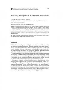
A large amount of results exists today on mobile robot navigation, most of them related to indoor navigation, wherein obstacles are rather structured, and the terrain flat, or in some limited cases, includes slopes. Mobility in outdoors environments have been demonstrated for road following (e.g., the ALV [1], the NAVLAB [2]), and also in limited environment conditions (e.g., Robby on a dry river bed [3] [4]), or for robots using legged locomotion (e.g., the Ambler [5]). In the "EDEN" experiment carried out at LAAS with the mobile robot ADAM 1 (figure 1), we aim to demonstrate a fully autonomous navigation in a natural environment, including perception, environment modelling, robot localization, and motion planning and execution on flat or uneven terrain. The canonical task is "GO-TO (Landmark)" in an initially unknown environment that is gradually discovered by the robot. The landmark is an object known by its model, which can be recognised and localized on a video or laser image. ADAM is equipped with a 3D scanning laser range finder, two orientable color cameras, and a 3-axis inertial platform. The motion controller also provides for odometry. On-board computing equipement is composed of two VME racks, one for locomotion and attitude control, and the other for the perceptual and decisional functions. All the functions developed for this experiment 1ADAM: "Advanced Demonstrator for Autonomy and Mobility" is property of FRAMATOME and MATRA MARCONI Space, currently lent to LAAS.
426
Figure 1. The mobile robot Adam. are encapsulated in modules integrated together in a real-time environment for autonomous operation (section 5). The laser range finder and the stereovision system are used for terrain modelling. During robot motion, a surveillance mode in which the laser scans a line two meters ahead can be activated. The landmark position is given approximately, and is not necessarily in the field of view in the initial position of the robot. From the approximate given position of the landmark (e.g., 50 m, N-W.), goal coordinates are determined. The general approach that we have implemented is an incremental navigation that proceeds until the final goal is reached. Its main elements are the following, and will be detailed in the corresponding sections: In a natural terrain, there may be. areas that are rather flat - cluttered or not by obstacles - and others which are uneven with respect to the locomotion capacities of the robot. Detailed modelling of the terrain is complex and resource consuming. Hence, we first use a simple algorithm to characterize the terrain into five classes: flat, with slope, uneven, obstacle and unknown (section 2.2). Only the uneven terrain regions will be modelled more accurately with an elevation map if necessary, i.e., if the robot has to move through such regions. A global navigation planner selects a subgoal within the known part of the environment, taking into account the nature of the regions to be crossed. The subgoal may be associated with a perception task to acquire new data. • The adequate navigation mode is selected according to the nature of the traversed terrain: a reflex mode if the terrain is flat and free, a 2D planned
427
motion if the terrain is flat and cluttered, or a 3D planned motion if it is uneven. (§3). • After execution of the trajectory to the subgoal, the landmark is observed (if possible) and its position updated. A new terrain acquisition and classification is performed, and the procedure is iterated. Navigation strategies concern motion strategies (definition of intermediate goals and navigation modes) and perception strategies (choice of the perception tasks to perform, point of view, etc.). The type of perception task necessary at a step of the mission execution is derived from an analysis of the result of the motion strategy: if an uneven area has to be crossed, it must then be interpolated, if the global goal to reach is in an unknown area, the model has to be completed, etc. Terrain modelling mainly relies on laser data, but fusion with color stereo (currently under development) enables to interpret the nature of the terrain (§6). The control system that executes the navigation procedure interprets the task and sequences the functional modules for its execution according to the context and specific modalities (§4). It selects the adequate sensors (vision, laser) according to the landmark description, the lighting conditions, etc. It also selects the motion planner that is adapted to the nature of the terrain to be traversed, and sets the conditions/reactions in case unexpected events are detected (e.g., obstacles). It sets the conditions for the achievement of the task, i.e., proximity and visibility of the landmark, and stops the robot near the landmark. The control system also verifies the coherence of the various functions (e.g., robot and target localization, motion execution). We now detail these different issues. 2. E n v i r o n m e n t
Representations
The complexity of a natural environment emphasizes the importance of the choice of adequate representations to model it: they must be easily manipulated, and also be welt adapted to the main tasks involved during navigation. We present in this section a structural scheme in which are embedded all the different representations that coexist in the system, and briefly describe three important perception processes applied on 3D data provided by a laser range finder (LRF) or a correlation stereovision algorithm. 2.1. T y p e s of M o d e l s and R e l a t i o n s h i p s The difficulty of modelling outdoor environments comes essentially from the fact that they are not intrinsically structured, as compared to indoor environments where simple geometric primitives match the reality. We have therefore favored the development of simple representations (polygonal maps, elevation maps...), easier to build and manage than those based on complex geometric primitives (linear or second degree surfaces, superquadrics...). Such more complex primitives can always be extracted from these basic representations if
428 necessary. In addition, semantic informations (e.g., the nature of some areas) can be easily included as labels in these representations. The other characteristics of the representations are related to the robot sensors and task, namely navigation: • The sensors are always imperfect: their data are uncomplete (lack of information concerning existing features) and not precise. They generate artefacts (information on non-existing features) and errors (wrong information concerning existing features). The same area when perceived again can therefore be differently represented. Hence environment representations must tolerate important variations [6]. • The environment is i n c r e m e n t a l l y discovered: we must be able to manage local momentary representations, and merge them in a global description of the world2. During the navigation, environment representations are needed for three main functions: • T r a j e c t o r y planning: we consider three different navigation modes, depending on the nature of the areas to be crossed. The reflex navigation mode does not need any numeric information concerning the environment, as opposed to the other modes: the 2D planner [7] requires in our case a binary bitmap description, and the 3D planner [8] builds its own data structure on the basis of an elevation map on a regular cartesian grid. • Localization: Localization based on environment features is always necessaxy, be it to correct odometry and inertial platform drifts. Specific representations of the environment are neccessary for this: a set of 3D points in the case of a correlation-based localization (iconic matching [9]), or a global map of detected landmarks (that must then be modeled, using particular geometric descriptions) in the case of a feature-based localization that we use [10]. • S t r a t e g i c decisions: To perform the navigation strategies, a topological description of the perceived environment is necessary; we use an adjacency graph of labelled regions, on which classical heuristic search is performed [7]. As for the perception planning process, we use the bitmap description resulting from the terrain classification procedure (section 2.2). To manage these different representations and maintain a global coherence, we developed a multi-layered heterogeneous model of the environment. In this model, the relationships between the various representations are of three different kinds (Figure 2): • Functional: All the representations are not necessary at all times, but some are, such as the representation needed to perform strategic choices, in which the localization model must be included for instance (arrows labeled "1" in the figure); • Spatial: There are areas of the perceived environment which may be more detailed to perform specific tasks such as 3D motion planning, localization, or object recognition3...(arrows labeled "2"); 2 A globM r e p r e s e n t a t i o n is n e e d e d for an efficient n a v i g a t i o n . 3for t h i s last p u r p o s e , we a r e i n v e s t i g a t i n g t h e use o f s u p e r q u a d r i c s
429
• C o n s t r u c t i v e : Some representations are determined on the basis of an other one (arrows labeled "3"). TOP LEVEL
Y CONNECTION GRAPH
, / / / / / I /
//.::_-(_-::_-///////// f
/
/\/
...........
I
~" / _ x
..... _\___L
re--
,,.
.
.
.
~x
......................
¥
////=x ELEVATIONMAP
SUPERQUADRICS
............
........
1
.......................... ,t.;;___.-. .... 7--;/-) "t:.L../ x 1' X X X=x
Figure 2. T h e representations
used
in
the s y s t e m
The top level of this heterogeneous model is a "bitmap" description of the environment, built upon the results of the fast terrain analysis algorithm (§2.2). The information encoded in every pixel of this bitmap is the terrain label and its confidence level, the estimated elevation, the identification of the region it belongs to. This structure is simple, adapted to the lack of geometrical structure of the environment, and flexible, in the sense that any supplementary information can easily be encoded in a pixel without reconfiguring the entire description and the algorithms that use it. Moreover, the techniques that allow to extract structured informations (regions, connexity...) from a bitmap are well known and easily implemented. The main drawback of a bitmap representation is its memory occupancy, that rapidly becomes huge if it covers a large area. To cope with this, a "sliding bitmap" structure is used: only the area surrounding the robot, with a size limited by the sensor capacities and the local navigation needs, is described as a bitmap, whereas the remaining of the already perceived terrain is structured using a region merging algorithm (or any other classical image compression algorithm), that leads to a much more compact description. 2.2. T e r r a i n Classification Developing a method that allows to quickly determine the nature of the terrain is essential in our adaptative navigation approach: as explained in the introduction, this process is systematically applied on the 3D data produced by the sensors, and is the basis of the global model of the environment on which the strategic decisions are taken. Using this method, we aim at developing a
430 "smarter" use of perception: time and resource consuming procedures, such as building a digital elevation map, are activated only when necessary, and are controlled in order to provide the useful information. The principle of the classification method relies on a discretization of the perceived aera in "cells", that correspond to the projection on a virtual horizontal ground of a regular grid in the sensor frame (figure 3). If we observe the orthogonal projection of a set of 3D points along the vertical axis (figure 4), one can note that the density of the points corresponding to the flat ground is a decreasing function of their distance to the sensor, which directly depends on the scanning mode of the sensor. The obstacles correspond to a very high density of the projected points, whereas occluded areas have a very low density (theoretically null). Our discretization respects this property: all the cells covering flat areas contain a constant number of points, defined by the discretization rates, whereas the cells correponding to obstacles have a much greater number of points, and the ones correponding to "shadows" are empty.
Figure 3. Discretization of the pereived area
This "cell density" information, along with other characteristics (mean altitude value, variance on the altitude, mean normal vector and variances on its coordinate) help to heuristicMly give a label to each cell as one of {Flat, Slope,
Uneven, Obstacle, Unknown}.
The classification method has been run on a large number of different images and gives significant results. It is especially weakly affected by the sensor's noise
431
Figure 4. Vertical projection of a 3D i m a g e (uncertainties and errors). It takes a reasonable time: the complexity of the procedure is O(n), where n is the number of 3D points in the image. Figure 5 is a camera view of a scene composed of flat and very uneven areas. The corresponding classification result is illustrated in increasingly gray levels (from Unknown to Obstacle) in figure 6. Fusion procedure The main problem raised by the fusion 4 of different perceptions is a possibly conflicting labelling of an area from a perception to another. These conflicts are due to the uncertainties of the sensor, whose behavior has therefore to be modeled to quantify the confidence on the d a t a it returns. The behavior of the logical sensor "terrain classifier" is a consequence of the range finder features whose accuracy on a 3D point coordinates is a decreasing function of the distance p. Hence the confidence on the label of each cell also decreases with its distance to the sensor. Another obvious observation is that this label confidence also depends on the label itself: for instance, a flat cell containing a few erroneous points can be labeled as an "uneven" one, whereas the probability that erroneous points perceived on an actually uneven zone lead to a "flat" label is very low. Figure shows a qualitative 5 estimate of the error probability P(e) on a cell label. 4 "fusion" here should be understood here as "aggregation", i.e., without position updating. Localization is performed by another system. 5The quantitative estimations are statistically determined.
432
Figure 5. Video Image Fusion is a simple procedure: each cell resulting from the classification procedure is written in the bitmap using a polygon filling algorithm. When a pixel has already been perceived, the possible conflict with the new perception is solved by comparing the label confidence values. Figure 8 shows the fusion of 3 perceptions. Many experiments have proved the robustness of this fusion method. Let's note that the confidence on the labels is also taken into account for the purpose of navigation strategies: it is essential that the artefacts (essentially badly labeled "obstacle" cells) due to the classification procedure do not mislead the robot's navigation.
3. M o t i o n P l a n n i n g A reflex navigation mode enables to skip the modelling and motion planning steps. If the terrain to be traversed is flat and empty from obstacles, then the robot heads directly to its goal. If obstacles are detected by a proximity sensor (the surveillance mode of the LRF), the robot stops, and the nominal procedure of terrain modelling is started. The appropriate decision is taken after classification. The nominM case is that motion planning is necessary. For this, we use two different motion planners according as the label of the regions to be crossed, is flat or uneven terrain.
433
Figure 6. C l a s s i f i c a t i o n R e s u l t . F r o m c l e a r t o d a r k : u n k n o w n , h o r i z o n t a l , flat w i t h s l o p e , u n e v e n , o b s t a cle)
P(error)
Label Uneven/Obst.
. q . _ _ Flat i5
0
110
t15 D-senser (meters)
Figure 7. E r r o r p r o b a b i l i t y o n cell l a b e l i n g 3.1. F l a t T e r r a i n The trajectory is searched with a simplified and fast method, based on bitmap and potential fields techniques. The robot is approximated by a circle, and its configuration space is two dimensional, corresponding to the robot's position
434
!!!!i)iiiii!)iii!!iiiil)iiiiiiii!
iiiiiii E
Figure 8. F u s i o n o f 3 p e r c e p t i o n s in the horizontal plane. P a t h planning, detailed in [11], is done as follows : 1. A binary bitmap free/obstacle is built over the region to be crossed. 2. A distance propagation method similar to those presented in [12] produces a distance map and a discrete vorono'/diagram. 3. This diagram is searched for a path reaching the goal. . A set of line segments is then extracted from this first path, and optimised in order to provide an executable trajectory, consisting of a minimum of straight lines separated by rotations. Search time depends only on the bitmap discretization, and not on the complexity of the environement. This is very important in natural environments with an arbitrary high complexity. The path is obtained in at most 2.5 seconds on a 256 × 256 bitmap, on a Sparc 10 workstation. 3.2. U n e v e n T e r r a i n On uneven terrain, irregularities are important enough to alter the attitude and the motion of the robot. Here a more precise representation of the terrain in terms of an elevation map is necessary (with a step of 10 cm in our case). The path generated by the planner must verify the following constraints: • The robot does not collide with the ground. • The robot does not tip-over.
435 • the suspensions cannot be stretched beyond some limit length. • The motion verifies the kinematic constraints of the vehicle. A path planner, first presented in [8], generates incrementally a graph of configurations reached by a sequence of constant controls (i.e. rotations and straight lines, in the case of ADAM). The solution is obtained by searching this graph, using an A* algorithm. In the case of incremental exploration of the environment, an additional constraint must be taken into account: the existence of unknown areas on the terrain elevation map. Indeed, any terrain irregularity can hide part of the ground. The map generated contains blind areas, where elevation values are not known. The path planner must avoid such unknown areas, when it is possible 6 . Otherwise, the planner must search the best way through unknown areas, and provide the best perception point of view on the way to the goal. This is performed with the following operations [11]: • First, the unknown areas of the elevation map are filled by an interpolation operation, which provides a continuous elevation map. • The planner can then search a way through unknown parts of the map. However, the avoidance of unknown areas is obtained by an adapted ponderation of the arc cost. • In order to improve the heuristic guidance of the search, a new heuristic distance to the goal is built by bitmap techniques. A cost bitmap is first computed, including the difficulty of the terrain, and the proportion of unknown areas around the current patch. A potential propagation from the goal generates a distance information corresponding to the best way to the goal through terrain relief and unknown areas. Once a trajectory reaching the goal is obtained, the first unknown area crossed by the robot is searched for. The trajectory is then truncated at the last point enabling to watch this area. The result is a motion stopped at the best point for a new perception. Search time strongly depends on the difficulty of the terrain. The computation of the bitmap heuristic distance takes around 40 seconds for a 150 x 200 terrain map, and path search takes between 20 seconds to a few minutes, on Indigo R4000 Silicon Graphics workstations. Figure 9 shows a trajectory computed on a real terrain. The dark areas correspond to interpolated unknown terrain. 4.
System
Architecture
and
Control
4.1. O v e r v i e w The generic control architecture for the autonomous mobile robots developed at LAAS is organized into three levels [13, 14]. It is instanciated in the case of 6 T h i s is a c a u t i o n c o n s t r a i n t
w h i c h c a n b e m o r e o r less r e l a x e d .
436
(B)
Figure 9. Start (A) and goal (B) configurations, and the trajectory (C) found in 30see. CPU. the EDEN experiment as shown in figure 10. The higher task planning level plans the mission specified by the operator in terms of tasks, with temporal constraints, interpretable by the robot and follows the execution of the mission. This level is not currently used in the experiment and will be embedded in a teleprogramming environment for experimenting the approach we propose for the development of intervention robots (e.g., for planet exploration) [15]. The on-board "Decisional Level" plans ~ the actions involved in the task here navigation - and controls their real-time execution according to the context and the robot state to achieve them. The "Functional Level" embeds the onboard functions related to the control of sensors and processing of their data, and to trajectory planning and control of the effectors. 4.2. T h e F u n c t i o n a l Level The Functional Level includes the functions for acting (wheels, perception platform), sensing (laser, cameras, odometry and inertial platform) and for various data processing (feedback control, image processing, terrain representation, trajectory computation, ... ). To control robot functionalities and underlying resources, these functions 7We also use the word "refinement"instead of planning for this level.
437 OPERATOR
Y_ TASK PLANNING ] ~lqD
CONTROL
[NAVIGATIONL . . . . J NAVIGATION ISUPERVI~)R ~ PLANNING , ........ I)~.~ISIONAL
t
/
~ob~ar~ ~
\ ~wt~e
/
EXECUTIVE
:~F'~:'
~.~
! FUNCTIONAL LEVEL
, f2D
i
~ !
I ! mol~ i i~'!
r :t~. ' ~ I 3D traj
i ...........
1I .
.
.
.
.
.
.
.
i
.
.
.
.
.
.
.
.
.
.
.
.
.
!
;,~
30"-\
.
...........
Figure 10. between flow.
the
Global control architecture. modules at the functional
Connections level show data
are embedded into modules defined in a .systematic and formal way, according to data or resources sharing. Thus, modules are servers which are called via a standard interface. This allows to combine or to redesign easily the functions. Figure 10 shows the set of modules used for the experimentation and the data flow during the progress of a specific iteration. The connections are dynamically established by the decisional level according to the context. For instance the position of the robot is updated when the estimated deviation is higher than a fixed threshold; the visibility of the target is necessary to update its position. Let's describe the steps executed during a nominal iteration: 1. A video image is acquired in the direction of the target (Video acqui-
sition module). 2. The target is identified in a video image and localized in a global reference frame ( T a r g e t r e c o g n i t i o n m o d u l e ) . From the position of the target, the final goal (e.g. at a given distance in front of the target) is determined.
438 3. A 3D depth map is acquired ( L a s e r r a n g e - f i n d e r m o d u l e ) . . Using the laser image, the terrain is classified and the regions representation updated ( T e r r a i n c l a s s i f i c a t i o n m o d u l e , §2.2). From this representation, the navigation planner in the decisional level selected sub-goals within the navigable regions. . If an uneven region is to be crossed, an corresponding elevation map is computed ( D i g i t a l E l e v a t i o n M a p m o d u l e ) . . The most suitable trajectory planner (2D or 3D) is used, according to the regions to be crossed, to find a trajectory inside the selected regions to reach the sub-goals (2D t r a j e c t o r y p l a n n e r a n d 3D t r a j e c t o r y p l a n n e r m o d u l e s , §3). . The trajectory is executed with a feedback control loop on the position given by the odometry ( M o t i o n C o n t r o l m o d u l e ) . . The position of the robot is updated if needed necessary ( R o b o t L o c a l isation module). 4.3. T h e D e c i s i o n a l L e v e l This level includes the system that plans the navigation actions (navigation planner), and a supervisor that establishes the dependencies between modules in order to combine the functions according to the context and modalities at run-time. It also checks the conditions/reactions in case of external events. For example it will watch for obstacles when executing a trajectory. The "Executive" at the decisional level sends the requests to the functional level modules and checks the coherence of the various concurrent primitives. Each of these subsytems is described below. However, in our current implementation, the three entities of the decisional level have been simplified and merged together. They are implemented using PRS (Procedural reasoning System) [16]. 4.3.1. T h e S u p e r v i s o r It receives a task to be executed and the associated events to watch for. The new task s is described in terms of actions to be carried out and modalities [14]. If the task is not directly executable, the supervisor calls the navigation planner that transforms it into the actions according to the knowledge on the environment, the execution modalities and robot state. The supervisor watches for events (obstacles, time-out, etc.), and reacts to them as planned and according to the dynamics of the situation and the state of the other running tasks. It sends to the Executive the different sequences of actions which correspond to the task. The supervisor sends back to the task planner (or the operator) the informations related to task (e.g., specific data) and the report about its execution. 8The task is in general not only related to navigation, and may include temporal constraints; however we focus here on navigation.
439 4.3.2. T h e N a v i g a t i o n P l a n n e r In general, it is necessary to refine the task since the environment is roughly known at the moment of the task planning. The refinement planner uses procedures to carry out the task which is more or less decomposed in executable actions. Thus the purpose of the refinement planner is to produce a sequence of elementary actions, at run-time, on the basis of the current environment state, the modalities specified with the tasks, and the state of the robot. This is done in bounded time. The navigation procedure includes all the steps described above for the recognition of the target and landmarks, and the decision about the navigation modes and strategies. 4.3.3. T h e E x e c u t i v e The executive launches the execution of actions by sending the related requests to the functional level modules. The parallelism of some sequences is taken into account: for instance the robot concurrently analyses the laser data and looks for the landmark, or moves toward a sub-goal while watching for obstacles. It sends back to the supervisor reports about the fulfilment of those basic actions. Futhermore the executive manages the access to ressources, the coherence of multiple requests at the syntactic level (for instance one cannot require concurrently the use of the laser to acquire data and the execution of a trajectory). 4.4. P R S : P r o c e d u r a l R e a s o n i n g S y s t e m To implement this control architecture we have used C-PRS [16]. It is an environment to develop and execute operational procedures (called "Knowledge Areas" : KA) which seemed well-designed to cope with the constraints of the control architecture. The representation is procedural which is convenient to define the different actions needed to carry out a task or to introduce some heuristic reasoning in case of non-nominal situations. The choice of the best procedure to solve a given sub-goal can be stated on the basis of the data corresponding to the context of execution or deduced by a meta-procedure that reasons about the best applicability of such procedures. As an example, we describe the procedure "Goto Landmark loop" (Figure 11) which will loop until Adam has reached its goal. It achieves the goal (! (GOT0_LANDMARK))which is posted by another KA ("Goto Cible"), the top level procedure that initializes the experiment. There is one interesting contruction in this procedure: the parallel execution of two goals in their own thread. It starts by checking if it has reached the terminal area. If it has, the procedure ends after achieving the goal. Otherwise, it posts 2 goals in parallel, ° ( ! (UPDATE_GOAL_POSITION)) and ( ! (UPDATE_NAVIGATION_MAP)). The execution then proceeds with a join node, which means that whichever thread will complete first will have to wait the second one. From then, it is straight forward and loop back on the start node. 9The thick bottom of a node indicates that it is a "split"node. Similarly, a thick top of a node indicates a "join" of parallel threads.
440
Goto LandmarkLoop (!
(! (GOIO_L~I)t'IC~X>)