Doctor of Philosophy in. Energy Engineering and ... Robert Ghirlando of the University of Malta kindly provided a thorough proofreading of the manuscript, ...
University of Florence Department of industrial engineering -‐ DIEF Thesis submitted in fulfilment of the requirements for the degree of
Doctor of Philosophy in Energy Engineering and Innovative Industrial Technologies PhD School in Industrial Engineering – XXVII Cycle (2012-‐2014)
Biomass pyrolysis for liquid biofuels: production and use
Tutor Prof. Francesco Martelli
Co-‐Tutor Prof. David Chiaramonti, PhD
External Advisor Prof. Marco Baratieri, PhD PhD Course Coordinator Prof. Maurizio De Lucia Florence, Italy, December 2014
Candidate Eng. Andrea Maria Rizzo
To Elena and Sibilla, my two princesses
Declaration
Declaration I hereby declare that this submission is my own work, and to the best of my knowledge and belief, it contains no material previously published or written by another person, nor material which to a substantial extent has been accepted for the award of any other degree or diploma at University of Florence or any other educational institution, except where due references are provided in the thesis itself. Any contribution made to the research by others I have been working with is explicitly acknowledged in the thesis. Andrea Maria Rizzo Florence, December 2014
University of Florence, “DIEF” Department of Industrial Engineering
I
Acknowledgments
II
University of Florence, DIEF -‐ Department of Industrial Engineering
Acknowledgments
Acknowledgments I would like to express my deepest and most sincere gratitude to all those people who gave me the opportunity and privilege of practicing Research, a profession amid the most fascinating. I’m indebted to David Chiaramonti and my parents Miriam and Felice for this. During the MSc it was just you and me, for my PhD we’re going to be three. What about a Postdoc, my heart? Crowded of colleagues and ideas, the office couldn’t be a better place to stay: thanks to Daniela and the three musketeers (Renato, Marco & Marco), for making it possible! Prof. Marco Baratieri of the Free University of Bozen reviewed this manuscript and provided several valuable suggestions; many thanks for his effort, encouragement, valuable suggestions and fruitful discussions. Prof. Robert Ghirlando of the University of Malta kindly provided a thorough proofreading of the manuscript, greatly improving the language quality. His unsolicited and highly appreciated help was a notable example of academic commitment. Last but not least, I gratefully acknowledge the help, support, friendship of all the important people of my life: my family – Giacomo & Nuschka, Lorenzo, Riccardo, Achille, Eva, Leonardo, Luca, Pino, Piera, Anna, all the aunts, uncles and cousins – and indeed all of my friends, colleagues and the group leader Prof. Francesco Martelli.
University of Florence, “DIEF” Department of Industrial Engineering
III
Acknowledgments
IV
University of Florence, DIEF -‐ Department of Industrial Engineering
Contents
University of Florence, “DIEF” Department of Industrial Engineering
V
Contents
Contents
Declaration ....................................................................................................................... I Acknowledgments .......................................................................................................... III Contents ......................................................................................................................... VI List of figures .................................................................................................................. IX List of tables ................................................................................................................... XII List of symbols and abbreviations ................................................................................ XIV Summary .......................................................................................................................... 1 1 Pyrolysis for fuel, energy and chemicals ................................................................... 3 1.1 Schematic process pathway ............................................................................... 4 1.2 General working principle ................................................................................... 6 1.2.1 Plant design alternatives ............................................................................... 7 1.2.2 Pyrolysis oil properties .................................................................................. 8 1.2.3 Pyrolysis process energy balance .................................................................. 9 1.2.4 Pyrolysis process economics ....................................................................... 11 1.3 Exploiting the potential of pyrolysis oil ............................................................ 12 1.3.1 Heat and power generation ........................................................................ 13 1.3.2 Fuels ............................................................................................................ 17 1.3.3 Chemicals .................................................................................................... 18 1.4 Industrial and demonstration project ............................................................... 20 1.4.1 Empyro B.V (The Netherlands) ................................................................... 20 1.4.2 Fortum (Finland) ......................................................................................... 21 1.5 Synthetic review of microalgae pyrolysis ......................................................... 22 1.6 Synthetic review of scrap tires pyrolysis ........................................................... 29 2 Bio-‐oil production in a pilot test bench ................................................................... 33 2.1 Description of the experimental apparatus ...................................................... 34
VI
University of Florence, DIEF -‐ Department of Industrial Engineering
Contents
2.1.1 Pyrolysis reactor .......................................................................................... 34 2.1.2 Feeding system ........................................................................................... 35 2.1.3 Bio-‐oil condensation and collection ............................................................ 36 2.1.4 Char collection ............................................................................................ 37 2.2 Test procedure .................................................................................................. 37 2.2.1 Feedstock conditioning ............................................................................... 38 2.2.2 Mass yield, energy recovery and carbon recovery of pyrolysis test ........... 39 2.2.3 Products analysis ......................................................................................... 40 3 Experimental results ................................................................................................ 41 3.1 Pyrolysis oil from lignocellulosic feedstock ....................................................... 41 3.1.1 Analysis of the feedstock ............................................................................ 41 3.1.2 Pyrolysis experiments ................................................................................. 43 3.1.3 Bio-‐oil yield and characterization ................................................................ 44 3.2 Pyrolysis oil from microalgae ............................................................................ 50 3.2.1 Analysis of the feedstock ............................................................................ 50 3.2.2 Bio-‐oil yield .................................................................................................. 52 3.2.3 Bio-‐oil characterization ............................................................................... 54 3.2.4 GC-‐MS analyses of bio-‐oils .......................................................................... 59 3.3 Material compatibility test of bio-‐oil samples .................................................. 61 3.3.1 Test procedure ............................................................................................ 64 3.3.2 Bio-‐oil samples ............................................................................................ 66 3.3.3 Results with elastomeric specimens ........................................................... 67 3.3.4 Results with metallic specimens ................................................................. 70 4 Use of bio-‐oils in a modified micro gas turbine ....................................................... 75 4.1 Description of the biofuel test bench ............................................................... 76 4.2 Turbine test of pine chips pyrolysis oil .............................................................. 78 4.2.1 Combustor redesign procedure .................................................................. 78 4.2.2 Firing test of new combustor with reference fuels ..................................... 80 4.2.3 Firing test of new combustor with bio-‐oil and bio-‐oil blends ..................... 82 4.3 Turbine test of scrap tire pyrolysis oil ............................................................... 85
University of Florence, “DIEF” Department of Industrial Engineering
VII
Contents
4.3.1 Firing test of STPO ....................................................................................... 85 5 Conclusions .............................................................................................................. 88 6 References ............................................................................................................... 90 Appendix A: analytical procedures .............................................................................. 102 Appendix B: GC-‐MS of pyrolysis liquids ....................................................................... 108
VIII
University of Florence, DIEF -‐ Department of Industrial Engineering
List of figures
List of figures Figure 1.1: Schematic of wood pyrolysis (adapted from [12–14]). ................................. 5 Figure 1.2 : Schematic flowsheet of a pyrolysis conversion process. .............................. 6 Figure 1.3 : Schematic flowsheet of the Joensuu scale-‐up plant fed with forest residues (adapted from [36]). ...................................................................................................... 11 Figure 1.4: Range of products from BTX (adapted from [76]). ...................................... 19 Figure 1.5: Quarterly market price of benzene, toluene and mixed xylenes compared to crude oil Brent between 2007 and 2013. Source: Bloomberg. ...................................... 20 Figure 1.6: Pyrolysis plant integration at Joensuu premises. Source: Metso. ............... 22 Figure 1.7: Possible pathways for microalgae conversion [90]. ..................................... 24 Figure 1.8: Schematic TGA (a) and DTG (b) during pyrolysis of Chlorella P. Source (ibid). ....................................................................................................................................... 26 Figure 1.9: Schematic TGA (a) and DTG (b) during pyrolysis of Chlorella P. and Spirulina P. Source (ibid). .............................................................................................................. 26 Figure 1.10: (a) Product yields (on the basis of the dry weight of samples) of fast pyrolysis from microalgae. (b) Product yields of HC Chlorella P. at temperatures from 400 to 600°C. Source (ibid). ........................................................................................... 27 Figure 2.1 : Schematic of the batch pyrolysis reactor. ................................................... 35 Figure 2.2: Picture of the batch pyrolysis reactor (centre) and control panel (left). ..... 35 Figure 3.1: TGA of mixed wood chips at 15 °C/min up 900 °C in nitrogen (triplicate). Green: actual samples weight loss profile. Violet: derivative of weight loss (calculated). Red: furnace temperature profile. ................................................................................. 43 Figure 3.3: Nitrogen content of pyrolysis liquids vs. feedstock. .................................... 57
University of Florence, “DIEF” Department of Industrial Engineering
IX
List of figure
Figure 3.4: Measured HHV of bio-‐oils' organic phase vs. lipid content of original feed. 57 Figure 3.5: Viscosity of organic phase of bio-‐oils vs. temperature. .............................. 58 Figure 3.6: Viscosity of water-‐rich phase of bio-‐oils vs. temperature. ......................... 58 Figure 3.7: Relative distribution of compounds, grouped by classes, for the organic phases of the three bio-‐oil samples. ............................................................................. 60 Figure 3.8: Experimental setup for material compatibility testing of bio-‐oils. .............. 65 Figure 3.10: Elastomeric specimens before (left) and after (right) 72 h immersion at 80°C in the bio-‐oil from microalgae Chlorella. ............................................................... 69 Figure 3.11: Elastomeric specimens before (left) and after (right) 72 h immersion at 80°C in the BTG bio-‐oil from pine chips. ........................................................................ 69 Figure 3.12: Weight change of metals after 48 and 72 hours of immersion at 80°C. .... 71 Figure 3.13: Selected metal specimens after 72 h immersion at 80°C in bio-‐oils. ........ 73 Figure 4.1: Layout of the interconnection of test bench basic sub-‐assemblies. ............ 77 Figure 4.2: Schematic of the biofuel test bench and measurement points. .................. 77 Figure 4.3: Cumulative area of air passages along the axial direction of the combustor. ....................................................................................................................................... 79 Figure 4.4: Original and modified reverse flow, silo combustor of the micro gas turbine. ....................................................................................................................................... 79 Figure 4.5: CO concentration @15 %vol oxygen in the exhaust for the original and modified combustor. ..................................................................................................... 81 Figure 4.6: NOX concentration @15 %vol oxygen in the exhaust for the original and modified combustor. ..................................................................................................... 82 Figure 4.7: Exhaust temperature and fuel flowrate during the blend test (PO:Ethanol 25:75). ............................................................................................................................ 83 Figure 4.8: CO and NO concentration during the blend test (PO:Ethanol 25:75). ......... 83 Figure 4.9: Fuel injector before and after the test (left), and flame tube exit after test (right). ............................................................................................................................ 84 Table 4.2: Chemical analysis of scrap tire pyrolysis oil. ................................................. 85 Figure 4.10: Extract of exhaust gas measurements during a STOP firing test. .............. 87 Figure B.1: Chromatogram of the bio oil from Chlorella Ingrepro. ............................. 109
X
University of Florence, DIEF -‐ Department of Industrial Engineering
List of figures
Figure B.2: Chromatogram of the aqueous phase from Chlorella Ingrepro. ............... 109 Figure B.3: Chromatogram of the bio oil from Nannochloropsis HCMR. ..................... 109 Figure B.4: Chromatogram of the aqueous phase from Nannochloropsis HCMR. ...... 110 Figure B.5: Chromatogram of the bio-‐oil from Chlorella HCMR. ................................. 110 Figure B.6: Chromatogram of the aqueous phase from Chlorella HCMR. ................... 110
University of Florence, “DIEF” Department of Industrial Engineering
XI
List of tables
List of tables Table 1.1: Yield of products (%wt) according to biomass pyrolysis mode [10]. .............. 4 Table 1.2: Typical properties and characteristics of wood-‐derived bio-‐oil (adapted from [26]) ................................................................................................................................. 8 Table 2.1: Set point of process parameters in pyrolysis tests. ...................................... 38 Table 3.1: Proximate and ultimate analysis of the feedstock (mixed wood chips). ...... 42 Table 3.2: Mass yield, energy and carbon recovery in bio-‐oil from lignocellulosic feedstock. ...................................................................................................................... 48 Table 3.3: Properties of bio-‐oils from lignocellulosic feedstock. ................................... 49 Table 3.4: Compositional and ultimate analysis of microalgae feedstock. .................... 51 Table 3.5: Mass yield, energy and carbon recovery in bio-‐oil from microalgae feedstock. ...................................................................................................................... 53 Table 3.6: Chemical analysis of the bio-‐oil from microalgae pyrolysis. ......................... 55 Table 3.7: Chemical analysis of the acqueous phase from microalgae pyrolysis. ......... 56 Table 3.8: ASTM Requirements for pyrolysis liquid biofuels [144]. ............................... 63 Table 3.9: Chemical analysis of feedstock. .................................................................... 66 Table 3.10: Chemical analysis of BTG and microalgae bio-‐oils. .................................... 67 Table 4.1: Equivalence ratio (Φ) in the original and modified combustor at 20 and 12 kWe load. ....................................................................................................................... 80 Table 4.2: Chemical analysis of scrap tire pyrolysis oil. ................................................. 85 Table 4.3: Test conditions for the STPO test in micro gas turbine. ................................ 86 Table 4.4: Timeline of STPO test in micro gas turbine. .................................................. 86
XII
University of Florence, DIEF -‐ Department of Industrial Engineering
List of tables
University of Florence, “DIEF” Department of Industrial Engineering
XIII
List of symbols and acronyms
List of symbols and abbreviations %wt AC ad APU BHP BTG BTX CAD CFD CO db DTG(A) ECU EEC ELT EU FCU FP GC-‐MS HCMR HP, HT HR LHV LT MGT Mtoe NOx OD PO PBR PPH -‐ PHR RPM SFC STPO TGA TIT UHC wb
XIV
Weight percentage Alternate Current As determined Auxiliary Power Unit Brake Horse Power Biomass Technology Group Benzene -‐ Toluene -‐ Xylene Computer Aided Design Computational Fluid Dynamics Carbon Monoxide Dry basis Differential Thermo-‐Gravimetric (Analysis) Engine Control Unit Electronic Exciter Circuit End-‐of-‐Life Tires European Union Fuel Control unit Fast pyrolysis Gas Chromatography -‐ Mass Spectroscopy Hellenic Center for Marine Research High Pressure, Temperature Heat Rate Lower Heating Value (MJ/kg) Low Temperature Micro gas turbine Million ton of oil equivalent (1 kg oil equivalent = 41.87 MJ) Nitrogen Oxides Outer Diameter Pyrolysis oil Photo bio-‐reactor Pounds per Hour (lb(US)/h) Revolutions per Minute Specific Fuel Consumption Scrap tire pyrolysis oil Thermo Gravimetric Analysis Turbine Inlet Temperature, firing temperature Unburned Hydrocarbons Wet basis
University of Florence, DIEF -‐ Department of Industrial Engineering
Andrea Maria Rizzo -‐ Biomass pyrolysis for liquid biofuels: production and use
Summary Biomass pyrolysis is an advanced process in which an organic material is rapidly heated in a controlled environment and in the absence of oxygen to produce a liquid intermediate, the bio-‐oil, composed of hundreds of oxygenated compounds, which can be used directly to generate heat or further upgraded to a fossil-‐fuel substitute with improved properties, more suitable to be fed into a conventional oil refinery. This work deals with an experimental investigation in the production and use of biofuels and bioproducts from pyrolysis of several biomass species and alternative feedstock, for distributed energy generation or the production of chemical intermediates (biochemicals). Within the doctoral studies, a dedicated laboratory reactor was built for this scope and samples of pyrolysis oils have been produced from several biomasses, both lignocellulosic and microalgae, in sufficient amount to assess their properties as a fuel. Being a relatively novel bioliquid, material compatibility of microalgae bio-‐oil was addressed. Tests were carried out on selected metallic and elastomeric specimens to gain insight on handling and storage requirements and to compare the aggressiveness of pyrolysis oil from microalgae with the relatively more known pyrolysis oil from lignocellulosic biomasses. The results from the experimental test campaign, aimed at investigating the possibility of feeding pyrolysis oils to a modified micro gas turbine for power generation, are then presented in the final part of the work.
University of Florence, DIEF -‐ Department of Industrial Engineering
1
-‐Introduction-‐
The chapter “Pyrolysis for fuel, energy and chemicals” illustrates some generalities on the pyrolysis oil as a liquid intermediate, along with a brief state of the art of pyrolysis technologies and frontiers. The industrial perspective of generating energy from pyrolysis oils is also addressed, and examples of current demonstration activities in Europe are presented. A synthetic review of literature on two specialized subjects, microalgae and scrap tires pyrolysis, closes the chapter. The chapter “Bio-‐oil production in a pilot test bench” describes the experimental set-‐up that was used in this thesis for the production and collection of bio-‐oil samples. The chapter “Experimental results” discusses the results from production and analysis of pyrolysis oil from several biomass samples in a dedicated laboratory reactor. The yield and properties of the produced pyrolysis oils are presented, discussed and compared one against the other; a large quantity of microalgae from three distinct strains have been converted to pyrolysis oil for the first time in such amount. The chapter also reports the results from laboratory trials aimed at a preliminary assessment of the compatibility of pyrolysis oil from microalgae with 7 commercial specimens of metals and elastomers, commonly used in engineering practice for storage, handling and processing of fuels or organic fluids. Pyrolysis oil from microalgae was compared with pyrolysis oil from pine chips, which is almost commercially available, and for which larger data sets have been generated in the past. Finally, the results of the test campaign on the micro gas turbine are presented in chapter “Use of bio-‐oils in a modified micro gas turbine”. The possibility to feed a modified micro gas turbine, previously adapted to biofuels, was evaluated and the unit tested with two distinct pyrolysis oils; the first was of biogenic origin (pine chips), the second was obtained from the pyrolysis of scrap tires. Test results are discussed along with the challenges associated with feeding pyrolysis oils to a stationary engine for distributed power generation.
2
University of Florence, DIEF -‐ Department of Industrial Engineering
Andrea Maria Rizzo -‐ Biomass pyrolysis for liquid biofuels: production and use
1 Pyrolysis for fuel, energy and chemicals Pyrolysis is the process of chemically decomposing organic materials by heating them in the absence of oxygen; the process is carried out at near atmospheric pressure and in the temperature range between 300 and 600 °C. Products of pyrolysis are a solid, also called char, a mixture of condensable vapours, and some permanent gases (mainly CO2, CO, CH4). The pyrolysis process is significantly flexible, as distribution of products, their relative abundance and properties can be influenced (steered) by properly tuning the process parameters or conditioning the feedstock, according to the desired final goal. A resume of the spectrum of products, in terms or relative abundance of liquid, solid and gas according to process conditions is reported in Table 1.1. Lower temperature, slower heating rate, larger particle size and longer residence time (slow pyrolysis) are known to promote the formation of solids, while higher temperature, faster heating rate, smaller particle size and shorter residence time favour the formation of condensable vapours (fast pyrolysis) [1,2]. However, a clear distinction between processes does not exist [3] or is arbitrary in many respects [4], and since many of these parameters cannot be accurately defined nor measured during fast pyrolysis, high external heat transfer coefficient and efficient primary products removal have been suggested by Lédé and Authier recently as general conditions that must be fulfilled at the level of the reacting biomass sample in fast pyrolysis [5].
University of Florence, DIEF -‐ Department of Industrial Engineering
3
Chapter 1
Research on slow pyrolysis (carbonization) for charcoal manufacturing dates back at least to mid-‐XIX century, when Violette reported on his investigation on the use of closed crucibles to enhance solid yield [6]. The process of carbonization has been applied since ancient times and it is still a widely diffused technique for the manufacturing of charcoal for household cooking and steel industries; according to Kammen & Lew, who reported FAO estimates, approx. 24 Mton of charcoal were already being produced annually in 1992 [7]. Systematic assessment of charcoal production technologies was carried out by Antal & Grønli [8], who devoted large efforts in optimizing process yields [9]. Nowadays, a renewed interest can be observed for the carbonization process in biochar manufacture for soil amendment, remediation and water treatment. Table 1.1: Yield of products (%wt) according to biomass pyrolysis mode [10]. Mode
Conditions
fast ≈500 °C, short hot vapours residence time ≈1 s intermediate ≈500 °C, hot vapours residence time 10-‐30 s slow ≈400 °C, long vapours residence (hours up to days) (carbonization) torrefaction ≈290 °C, solids residence time 10-‐60 min
a
b
Liquid %wt 75 a 50 30
Solid %wt 12 25 35
Gas %wt 13 25 35
b
80
20
0
: in 2 phases. : unless condensed, then up to 5%.
When fast and intermediate pyrolysis is applied, the rapid condensation of pyrolysis vapours and aerosols produces a dark brown mobile liquid, the bio-‐oil, that has a heating value about half that of conventional fuel oil; synonyms for bio-‐oil include pyrolysis oils, pyrolysis liquids, bio-‐crude oil (BCO), wood liquids, wood oil, liquid smoke, wood distillates, pyroligneous acid, and liquid wood [4]. The interest in pyrolysis for the production of liquid fuels resides in the possibility to convert a solid biomass into a liquid intermediate with higher energy density, improving transportation cost, logistics, and further processing (upgrading or use).
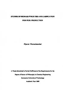
1.1 Schematic process pathway The simplified model of wood pyrolysis by Shafizadeh & Chin [11] helps in understanding the intricate sequence of reactions involved in the thermal degradation
4
University of Florence, DIEF -‐ Department of Industrial Engineering
Andrea Maria Rizzo -‐ Biomass pyrolysis for liquid biofuels: production and use
of biomass. Provided there is a sufficient heating rate, the biomass particle is decomposed to char and pyrolysis vapours, i.e. permanent gases (CO2, CO, CH4) and condensable liquids (reaction water, biomass moisture and organic products). In a successive phase, the evolved pyrolysis vapours may undergo a great number of secondary reactions, e.g. cracking and condensation. Their nature and extent may considerably modify the yields and properties of vapours and consequently those of bio-‐oil. These secondary reactions include homogeneous gas phase and/or heterogeneous solids (char, catalysts)/vapours cracking and repolymerisations, and the extent of these reactions depends on the temperature fields, as well as gas and solid phase residence times distributions [3], which is of course also a function of the reactor geometry and working principle. STEP$I$
STEP$II$
Gas'(g)'
BioDoil'(l)'
CO,'CO2,'CH4…'
Wood$(s)$ char'(s)'
STEP$III$ Char'(s)'+'gas'(CO2)' +'bioDoil'(l)'
Pyrolysis' vapors'(g)' Gas'(g)'
CO,'CO2,'CH4…'
Drying'+'primary' decomposi1on' reac1ons'
Secondary' cracking,'evapora1on,' condensa1on,'dehydra1on…'
Repolymeriza1on'
450$550°C'