Mar 4, 1996 - dispersion and self-phase modulation due to the Kerr non- linearity of the fiber. ..... The authors thank Michael Steel and Neil Broderick for.
VOLUME 76, NUMBER 10
PHYSICAL REVIEW LETTERS
4 MARCH 1996
Bragg Grating Solitons Benjamin J. Eggleton* and R. E. Slusher AT&T Bell Laboratories, Murray Hill, New Jersey 07974
C. Martijn de Sterke School of Physics and Optical Fibre Technology Centre, University of Sydney, New South Wales 2006, Australia
Peter A. Krug Optical Fibre Technology Centre, University of Sydney, New South Wales 2006, Australia
J. E. Sipe Department of Physics, University of Toronto, Ontario, Canada M5S 1A7 (Received 26 October 1995) We report the first experimental observation of nonlinear propagation effects in fiber Bragg gratings, resulting in nonlinear optical pulse compression and soliton propagation. The solitons occur at frequencies near the photonic band gap of the grating; they are due to a combination of the negative dispersion of the grating, which dominates the material dispersion, and self-phase modulation. The solitons propagate at velocities well below the speed of light in the uniform medium. PACS numbers: 42.65.Tg, 42.65.Vh, 42.81.Dp, 42.81.Wg
We observed nonlinear propagation effects in optical fiber Bragg gratings, in particular nonlinear pulse compression, and the generation of solitonlike pulses within the grating. In our experiments the dispersion is due to the grating, which dominates the dispersion of the background medium by several orders of magnitude. The solitons then arise from the balancing of this large grating dispersion and self-phase modulation due to the Kerr nonlinearity of the fiber. The grating dispersion allows the soliton to propagate at speeds substantially less than the velocity of light in the fiber in the absence of the grating; in fact, here we report soliton propagation at 76% of this velocity. This would be of both great fundamental interest and potential technological applications. For example, the large grating dispersion reduces typical interaction lengths for soliton formation by several orders of magnitude relative to that required in the absence of the grating. Correspondingly higher optical intensities are required, but not so high as to lead to fiber damage. Of course, nonlinear pulse propagation in optical fibers has been demonstrated using various techniques. Selfphase modulation (SPM) associated with the Kerr effect, when combined with external dispersive elements such as diffraction gratings, has been used to achieve nonlinear pulse compression in fibers [1]. Closely related are optical solitons [2], nonlinear pulses that propagate in a dispersive medium without changing shape [3]. But propagation of temporal optical solitons in uniform optical fibers is due to the balancing between the effects of the anomalous group velocity dispersion and SPM, and the small intrinsic material dispersion in optical fibers requires relatively long lengths of fiber—typically 100 m—for soliton formation. Increasing the fiber dispersion reduces the length of fiber necessary to form solitons. Fiber Bragg gratings 0031-9007y96y76(10)y1627(4)$10.00
[4] are optical elements which can provide strong dispersion. Here we consider Bragg gratings subject to incident intensities in the nonlinear regime, where most investigations to date have only been theoretical [5,6]. We mention two results of this theoretical work. The first is the prediction that pulses can propagate coherently through nonlinear fiber Bragg gratings in spite of the large dispersion. These pulses propagate at velocities that can be substantially less than the speed of light in the uniform medium. Here we shall refer to these pulses as Bragg grating solitons; these solitons exist due to the balancing between the SPM and the dispersion associated with the periodic variation in the refractive index rather than that intrinsic to the material. The well known gap solitons [5,6] are a class of Bragg grating solitons with a spectrum within the photonic band gap. A second result is that of Winful, who has theoretically described a form of nonlinear in-fiber compression using SPM and the dispersion provided by a Bragg grating [7]. Both of these results can be understood qualitatively. A fiber Bragg grating couples forward and backward traveling modes, and opens up a photonic band gap. While frequencies inside the gap are reflected, frequencies outside the gap propagate, but with a group velocity which can be substantially less than the speed of light in a uniform optical fiber. Consider a transform limited pulse tuned to a frequency just above the upper band edge of the photonic band gap where the grating is strongly dispersive while the reflectivity is small. At low intensities an input pulse at frequencies close to the gap edge has a group velocity below that of the uniform medium, but is broadened substantially upon propagation through the grating. However, in the nonlinear regime, SPM generates new frequency components which are redshifted near the leading edge and blueshifted near the trailing edge [8]. © 1996 The American Physical Society
1627
VOLUME 76, NUMBER 10
PHYSICAL REVIEW LETTERS
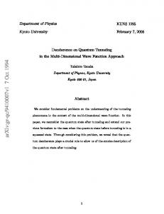
As the upper branch of the dispersion relation exhibits anomalous dispersion, the rear of the pulse travels faster than the front of the pulse, and if the incident pulse width is larger than the width of the fundamental soliton then the pulse undergoes compression initially. As the interaction continues the pulse shape adjusts itself until the two effects balance to maintain a pulse whose shape is approximately preserved, leading to the formation of a Bragg grating soliton. On the lower branch the dispersion is normal and the behavior is qualitatively different than that in the anomalous regime. In particular, the pulse broadens much more rapidly than it would at low intensities. The observation of nonlinear grating effects is dependent on the grating being long enough to allow a significant nonlinear phase shift to accumulate along its length. For this reason we fabricate gratings using the phase mask scanning technique which allows the production of long fiber gratings whose length is only limited by the length of the phase mask [9]. The grating transmission spectrum shown in Fig. 1 is obtained by varying an axial strain on the fiber so that the grating resonance scans with respect to the laser wavelength. Also shown in the figure is a pulse spectrum having a full width at half maximum (FWHM) equal to 0.03 nm. The length of the grating used in the experiment was L 55 mm. The magnitude of the average refractive index change was Dn 3 3 1024 , which corresponds to a total strength of kL ø 40, where k pDnhylB , h ø 0.8 is the fraction of the power guided in the core, and lB is the Bragg wavelength [6]. The experimental setup is shown in Fig. 2. High intensity transform limited pulses are generated by a modelocked, Q-switched YLF laser having a duration that can
FIG. 1. The measured transmission spectrum of the actual fiber grating used in the experiment. The grating length is 55 mm and has an average refractive index modulation of Dn 3 3 1024 . The dashed curve is the power spectrum of the incident pulse.
1628
4 MARCH 1996
be varied between 60 and 90 ps FWHM. A single pulse from the mode-locked train is selected so that a unique pulse intensity at a repetition rate of 500 Hz can be studied. The low repetition rate minimizes any possibility of heating or fiber damage. The pulses are coupled into the 4 mm diameter core using a microscope objective, and are attenuated so that the peak intensity can be varied in the range from 1 to 100 GWycm2 . The experimental intensities are known only to within 50% due to uncertainties in the core area and the measurement geometry. After propagation, the transmitted intensity is detected using a photodiode with a 9 ps rise time and a sampling oscilloscope with an 18 ps response time. A fast photodiode monitoring a split-off portion of the input pulse is used to trigger the sampling oscilloscope. The net time resolution, including trigger jitter, is approximately 20 ps. Only light propagating through the core is detected by using a spatial filter to remove the light guided by the cladding. To ensure that any measured nonlinear effects occur entirely within the grating and not, for example, from effects of SPM in the length of fiber preceding the grating, this length is minimized to less than 10 mm. Tuning of the grating wavelength relative to the laser wavelength is accomplished by straining the fiber using the displacement of a precision mechanical stage. Tuning well outside of the band gap, where the grating is 100% transmitting and the dispersion is negligible, results in a sublinear dependence of the transmitted intensity on incident intensity. There is no noticeable reshaping in the transmitted pulses. The interesting grating phenomena are observed when the grating is tuned such that the pulse spectrum is close to the edge of the band gap, where the grating is highly dispersive yet is not strongly reflecting. In the low power limit the transmitted pulse is broadened from approximately 80 to 90 ps, and the pulse peak is retarded by 75 ps relative to the transmitted pulse tuned far from the Bragg resonance. The solid line in Fig. 3 shows
FIG. 2. Schematic diagram of experiment. The total length of the fiber is 75 mm, the grating beginning approximately 10 mm from the front of the fiber and ending 10 mm from the back of the fiber.
VOLUME 76, NUMBER 10
PHYSICAL REVIEW LETTERS
the transmitted pulse, having a FWHM of approximately 80 ps and an input intensity of approximately 12 GWycm2 , when the pulse is detuned far from the band gap, so that grating dispersion may be neglected. This should be compared to the transmitted pulse at the same input intensity, but when the grating is tuned such that the pulse is centered on 1052.62 nm, where the grating transmission is approximately 75% in the linear limit (dashed line). The transmitted pulse now has a width of 25 ps, which, taking into account the resolution limit of the detection system, results in a FWHM approximately equal to 15 ps which corresponds to a compression factor of greater than 5. We note that the peak intensity of the compressed pulse is enhanced, showing true compression rather than pulse truncation. Note also that the compressed pulse leaves the grating about 85 ps later than the pulse propagating without dispersion. Since the length of the grating is 5.5 cm, the compressed pulse travels at an average velocity corresponding to 76% of the speed of light in the uniform fiber. This low velocity is a consequence of the grating dispersion, while pulse breakup is prevented by the nonlinearity. We note that the compression begins at intensities of approximately equal to 1 GWycm2 and reaches a minimum pulse width at intensities approaching 80 GWycm2 . Tuning the grating such that the pulse spectrum lies on the long wavelength side of the gap results in the transmitted pulse undergoing nonlinear pulse broadening. The nonlinearly broadened pulse has a measured FWHM of approximately 185 ps, representing a broadening factor greater than 2.0. Using nonlinear coupled mode equations [6], we modeled the propagation effects in the grating. Shown in
FIG. 3. Transmitted pulse, having FWHM ø80 ps when the grating is tuned far from the resonance, and the transmitted pulse and the compressed pulse having FWHM ø15 ps when the grating is tuned such that the pulse is centered on 1052.62 nm, where the grating transmission is approximately 75% in the linear limit. The time origin is arbitrary.
4 MARCH 1996
Fig. 4 is the calculated transmitted intensity for the case when the pulse is detuned far from the gap and the case in which the pulse is tuned close to the upper gap edge for parameters similar to those used in the experiment. The simulations do not include the effects of nonlinear losses, which were apparent in the experiment. Although we include the effects of SPM in the length of fiber preceding the grating, we find that for lengths less than 10 mm these effects are small. At low intensities we find that the transmitted pulse is broadened to 92 ps, in good agreement with experiment. At input intensities of 12 GWycm2 we find that the width (FWHM) of the compressed pulse is 20 ps, while the retardation of the peak of the compressed pulse with respect to the out-of-gap pulse is approximately 92 ps, also in good agreement with experiments. We have also numerically studied the evolution of the envelopes of the electric fields along the length of the grating. Because of the balancing of the group velocity dispersion with the nonlinearity, solitonlike pulses propagate along the length of the grating, with an approximately constant shape. The formation length of the Bragg grating soliton is approximately 2 cm, suggesting that in the experiment we are actually in the soliton regime. After undergoing an initial narrowing in the first few centimeters of the grating, the pulse’s intensity and width oscillate on a period of cm over a range of less than 50% as it propagates along the grating. The oscillations are associated with the initial pulse not being a perfect soliton. By numerically calculating the temporal Fourier spectrum of the fields inside the gratings, we note that most of the energy of the pulse lies just outside the band gap; we thus refer to these pulses as Bragg grating solitons. Breaking with usage to date [6], but adopting what we feel is a more appropriate nomenclature, we reserve the term “gap soliton”
FIG. 4. Numerical simulations of transmitted pulse when the pulse is centered on 1052.62 nm, where the grating transmission is approximately 75% in the linear limit.
1629
VOLUME 76, NUMBER 10
PHYSICAL REVIEW LETTERS
for pulses with a spectrum within the photonic band gap; gap solitons are thus a special class of Bragg grating solitons. The analytic form of Bragg grating solitons, which are characteristic for nonlinear periodic media, has been given by Aceves and Wabnitz [6,10]. In summary, we have demonstrated nonlinear propagation effects in fiber gratings fabricated using the phase mask scanning method. In the experiment, pulses generated by a mode-locked and Q-switched YLF laser are compressed by a factor of 5. The compression is intensity dependent and due to a combination of the “artificial” negative dispersion associated with the grating and the phase shift associated with the Kerr nonlinearity. Numerical analysis shows that gratings exhibit solitonlike properties at frequencies close to the edge of the band gap where the dispersion is high, and the grating is still transmissive. The authors thank Michael Steel and Neil Broderick for fruitful conversations. B. J. E. acknowledges the support of an APA and an ATERB. The Optical Fibre Technology Centre is a member in the Australian Photonics Cooperative Research Centre.
1630
4 MARCH 1996
*Permanent address: School of Physics and Optical Fibre Technology Centre, University of Sydney, New Sourth Wales, 2006, Australia. [1] A. M. Johnson and C. V. Shank, in The Continuum Laser Source, edited by R. R. Alfano (Springer-Verlag, New York, 1989), Chap. 10. [2] A. Hasagawa and F. Tappert, Appl. Phys. Lett. 23, 142 (1973). [3] L. F. Mollenauer, R. H. Stolen, and J. P. Gordon, Phys. Rev. Lett. 45, 1095 (1980). [4] G. Meltz, W. W. Morey, and W. H. Glenn, Opt. Lett. 14, 823 (1989). [5] W. Chen and D. L. Mills, Phys. Rev. Lett. 58, 160 (1987). [6] C. M. de Sterke and J. E. Sipe, in Progress in Optics XXXIII, edited by E. Wolf (Elsevier, Amsterdam, 1994), Chap. III. [7] H. G. Winful, Appl. Phys. Lett. 46, 527-529 (1985). [8] G. P. Agrawal, Nonlinear Fiber Optics (Academic Press, San Diego, 1989). [9] J. Martin and F. Ouellette, Electron. Lett. 30, 812-813 (1994). [10] A. B. Aceves and S. Wabnitz, Phys. Lett. A 141, 37-42 (1989).