Jul 15, 2001 - existing ones without sending a technician out in the field. This results ... The web movie service bytefile is the combination of software and.
Building a Virtual Framework for Networked Recon gurable Hardware and Software Objects Yajun Ha , Serge Vernalde, Patrick Schaumonty, Marc Engels, Rudy Lauwereinsz and Hugo De Manx IMEC, Kapeldreef 75, Leuven 3001, Belgium.
July 15, 2001 Abstract. A virtual framework that uses both hardware and software recon�gurable objects is presented. The new framework supports both networked hardware and software recon�guration. In such a virtual framework, the networked recon�guration users only need to develop a single service description targeted on a single hardware and software platform. The service is able to write once, and run everywhere. That facilitates the new service deployment and maintenance. We present the components, design �ow and implementation aspects of the virtual framework.
Keywords: platform-independence, networked recon�guration, computer architecture, design methodology
1. Introduction To reduce the time to market, and react to the fast changing standards in time, software and hardware recon�guration have been widely used in the industry. Recently, with the rapid development of the Internet and other enabling technologies, there is a trend to do the software and hardware recon�guration via the network. Updating software via the network with new enhancements and bug �xes is fairly common in the electronics industry. But remotely recon�guring hardware that uses programming logic devices such as �eld programming gate arrays (FPGAs) is a new concept that system manufacturers are just beginning to embrace �1]. To realize the networked hardware recon�guration, several challenging issues have to be solved. For example, platform independent hardware recon�guration is one of them. Platform independent hardware recon�guration could ease designers from making any assumption about the client platforms targeted by the transmitted programming information, although di erent client platforms may use di erent CPUs y z x
Yajun Ha is also Ph.D. candidate in K.U.Leuven, Belgium Patrick Schaumont is now Ph.D. candidate in UCLA, U.S.A. Rudy Lauwereins is also a professor in K.U.Leuven, Belgium Hugo De Man is also a professor in K.U.Leuven, Belgium c 2001 Kluwer Academic Publishers. Printed in the Netherlands.
jsc_paper.tex� 10/07/2001� 15:59� p.1
2
Yajun Ha et al
and FPGAs. Support of platform independent recon�guration is the primary aim of this work. A lot of industry and academic e orts have already been put in the development of design tools for network-oriented reon�guration. On the one hand for the industry category, design frameworks like Java �8] can support platform independent designs, but only with software components. Xilinx Online �1] is devoted to enable any network connected Xilinx programmable system that can be modi�ed after the system has been deployed in the �eld. But basically, it is a vendor speci�c approach, not a platform-independent one. On the other hand for the academic category, virtual hardware and circlets concepts had been raised by Brebner�2]�3]. The goal of circlets is to �nd a virtual description of circuits and integrated circlets with applets, which is quite similar to us. But they did not look at the interaction between the software and hardware. JHDL �4] proposes to use general-purpose programming languages Java for FPGA design. Their work is focused on using Java to describe hardware, but not to solve platform-independent issues for networked hardware recon�guration. Services that contain platform independent networked recon�gurable hardware and software objects need to be developed in a virtual design platform. This paper discusses the components, design �ow, and implementation aspects of such a virtual design framework. In the next section, the application background of the framework will be introduced. Then, we will describe the components that comprise the virtual framework. In section 4, the application design �ow is introduced. Being an innovative component of the virtual framework, the hardware virtual machine is discussed in section 5. In section 6, the service byte�le format is brie�y explained.
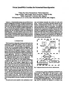
2. Application Background In the networked hardware recon�guration, the hardware recon�guration information is transported together with software from the service provider to the client. It enables to add new hardware features and �x existing ones without sending a technician out in the �eld. This results in big maintenance and deployment savings �6]. Networked recon�guration of both hardware and software has a major impact on the current Internet service industry. We will use the service of "Web Movie" (see Fig. 1) as an example to show how new services are expected to be deployed and maintained in the coming future. Suppose there is a client who wants to watch web movies. But he
jsc_paper.tex� 10/07/2001� 15:59� p.2
A Virtual Framework for Networked Recon guration
3
Client Web Movie Programmable Interface FPGA
Controller Native FPGA bitstream
Native application software code
HVM
SVM
Demultiplexing
Network Service Provider Web Page Downloading "Choose Movie" Service Bytefiles Software bytecode Hardware bytecode
Figure 1. Deployment of the web movie service with the virtual framework.
has neither the "Web Movie Player" nor the movie �les installed on his side. He goes to the web page of the web movie service provider, where he �nds the list of movies that are available. The client then points his mouse at one of the items and chooses his favorite movie. Upon receiving this request from the client, the service provider �rst detects that the client does not have a movie player. Therefore, it automatically sends the movie player service byte�le to the client. After the service byte�le has been successfully installed, the client can use the web movie player to playback the movie �les provided in the same or another service provider's site. The web movie service byte�le is the combination of software and hardware bytecode that realizes the web movie player. Normally, the software bytecode describes the user interface, hardware/software interface, and all the computationally non-intensive functions of the player. The hardware bytecode describes the FPGA recon�guration information that implements the computationally intensive functions like video decoding. By preparing the recon�guration information in an abstract bytecode format (which is abstract enough to be implemented on a wide variety of �xed hardware (Processors) and recon�gurable hardware (FPGA platforms)), the "Web Movie" service provider only needs to write the service byte�le once, and it can run on any client platform.
jsc_paper.tex� 10/07/2001� 15:59� p.3
4
Yajun Ha et al
3. Framework Description This section introduces the components of the virtual framework. Those components are residing on the service providers and clients respectively. They are shown in Fig. 2. We will only explain those blocks that are unique in this framework. Framework Components for the Service Provider
Framework Components for the Client
Application Demultiplexing Hardware-Software Co-Design
Software VM Precompiler
HVM
Hardware VM Precompiler
SVM
ASOS
FGPA
CPU
Bytecode Binder
Service Bytefile
Figure 2. Components of the virtual framework.
3.1. Components for the Service Provider Framework components for the service provider include a hardware and software codesign environment, software and hardware virtual machine precompilers, and a service bytecode binder. Current codesign environments �7] enable the designers to partition the application system between hardware and software, based on the desired performance-resource tradeo . With the tools in the codesign environment, an application is partitioned into di erent parts that will be implemented in hardware or software. To achieve the goal of write once, run everywhere, both hardware and software parts of the application will be mapped to their respective virtual machines by precompilers. The generated software and hardware bytecode will be combined by the bytecode binder to a service byte�le. The service byte�le is the information that will be transported from the service provider to the client. Of all the components on the server side, the hardware virtual machine precompiler is a new block that needs to be elaborated.
jsc_paper.tex� 10/07/2001� 15:59� p.4
A Virtual Framework for Networked Recon guration
5
3.1.1. Hardware Virtual Machine Precompiler The hardware virtual machine precompiler is used to generate abstract FPGA routing information. The gate-level netlist of the hardware design is �rst compiled and technology mapped to the abstract FPGA architecture model that will be discussed in section 4. Then it will be placed and pre-routed on the same model. The resulting physical design information will be written into a hardware bytecode �le. The abstract FPGA model is the bridge between the HVM precompiler and the HVM itself. 3.2. Components for the Client Framework components for the client include software and hardware virtual machines �5]�8], an architecture speci�c operating system (ASOS), �xed hardware like CPU and recon�gurable hardware like FPGAs. Compared to traditional components for a terminal, the hardware virtual machine and architecture speci�c operating system are especially added to build the networked virtual framework. 3.2.1. Hardware Virtual Machine The hardware virtual machine corresponds to the virtual machine in the software part. It works together with the software virtual machine to separate the whole architecture into architecture independent part and architecture speci�c part. The hardware and software bytecode run on the hardware and software virtual machines respectively. By providing a virtual world, the service provider only needs to provide a service description targeted towards the virtual platform comprised by the HVM and SVM. The implementation aspects of HVM will be discussed in section 4. 3.2.2. Architecture Speci c Operating System In a traditional terminal architecture, the ASOS is a real-time operating system. But in this scalable architecture, we have both �xed hardware like a CPU and recon�gurable hardware like FPGAs. Therefore, a new resource manager that can manage both �xed and recon�gurable hardware is needed. This new resource manager is the ASOS �6]. This will not be elaborated further in the scope of this paper.
4. Design Flow This section introduces the design �ow for the service development under the virtual framework. It describes the design �ow both for service providers and clients.
jsc_paper.tex� 10/07/2001� 15:59� p.5
6
Yajun Ha et al Application Concept Functional Modeling Demultiplexer Problem Partitioning
Software Functional Model
Interface Functional Model
Software Development
Hardware Functional Model Behavioral Synthesis RTL HDL
Software Bytecode
Hardware Bytecode
Software Virtual Machine
Hardware Virtual Machine
Native Application Software
Native FGPA Bitstream
Applicatin Source Code Logic Synthesis Precompile to Software Virtual Machine
Place and Preroute to Abstract FPGA
Software Bytecode
Hardware Bytecode
Controller
User Interface
Programmable Interface
FPGA Service Bytecode Binder
Network
Service Provider’s Side
Client’s Side
Figure 3. Design �ow of the virtual framework.
4.1. Design Flow on the Service Provider's Side In the service provider's side, a new service requirement is �rst thoroughly analyzed and well studied by the designers. In the �rst stage, the service is represented by a functional model. This functional model can be written in an special toolkit like Matlab, or general high level languages like C++ and Java. The functional model will be partitioned into three sub models in a hardware/software codesign environment. One sub model describes the application part that will be implemented in software. Another describes the application part that will be implemented in hardware. The third describes the interface between the partitioned hardware and software sub models. The sub models for the software and interface are gone through various phases of software development, which generates the detailed source code to implement the two sub models. The detailed source code is then precompiled into software bytecode by a software virtual machine precompiler. The sub model for the hardware is fed into a hardware design environment. After behavior synthesis, the sub model for the hardware will be transformed into a register transfer level (RTL) hardware description. The RTL description of the hardware can generate the gate-level netlist through logical synthesis. The hardware bytecode can be ob-
jsc_paper.tex� 10/07/2001� 15:59� p.6
A Virtual Framework for Networked Recon guration
7
tained by placing and pre-routing this gate level netlist on an abstract FPGA model. Both hardware and software bytecodes are sent to the service bytecode binder, which produces the combined service byte�les. 4.2. Design Flow on the Client's Side In the client's side, the received service byte�le is �rst demultiplexed to software and hardware bytecode respectively. Software bytecode is interpreted by the software virtual machine and turned into the native application software code that runs on the native CPU. On the other hand, the hardware bytecode is interpreted by the hardware virtual machine, and turned into native FPGA bitstreams that will con�gure native FPGA. When both the native application software code and the FPGA bitstream have been obtained, the native application software code will �rst de�ne the programmable interface via the controller. Through this de�ned interface, the native FPGA bitstreams will be sent to FPGA for recon�guration. The recon�gured FPGA can then be used as a hardware accelerator �9]. The native application software code interacts with the FPGA accelerator through the programmed interface. The native application software code sends the parameters and variables to the interface, and gets the results from that interface once the FPGA accelerator has �nished processing. The native application software code also provides the graphic user interface, such as menus, to interact with the user.
5. Hardware Virtual Machine As described in section 2 and section 3, the hardware virtual machine is the most innovative component of the whole framework. It is also the less researched �eld until now. This section describes the hardware virtual machine. Additionally, implementation of the abstract FPGA model converter will be brie�y introduced. The hardware bytecode is one of the topics in the next section, where we discuss the service byte�le format. 5.1. Virtual FPGA Model Like in commercial FPGAs, the abstract FPGA model (see Fig. 4) also contains three blocks. They are abstract logic block, abstract routing architecture, and abstract I/O pad.
jsc_paper.tex� 10/07/2001� 15:59� p.7
8
Yajun Ha et al Abstract logic block
X channel segment
Y channel segment Input Pin
I/O block Output pin
Figure 4. An abstract FPGA architecture.
5.1.1. Abstract Logic and I/O Block The logic block used in an FPGA strongly in�uences the FPGA speed and area-e�ciency. While many di erent logic blocks have been used in FPGAs, most current commercial FPGAs are using logic blocks based on look-up tables (LUTs). Accordingly, in our research, we will only build abstract logic block for those LUT-based FPGAs. One abstract basic logic block is shown in Fig. 5. It contains a K-input LUT (we choose K=4 in the example) to implement combinational logic, a D �ip-�op to implement sequential logic, and a multiplexer to choose the output �15]. The pin locations of an abstract logic block are chosen randomly, because they will be mapped to the real pin locations of the client FPGA later. Combination of abstract basic logic blocks can be used to describe a series of commercial logic blocks, such as those used in Altera 8K and 10K FPGAs �10], Xilinx 4000 and 5200 series �11]. Out 4-input Clock LUT
Inputs
D-FF
I_3 I_4 I_2
O_1 I_1 P_1 P_2
Figure 5. A basic logic block in the abstract FPGA.
Abstract I/O blocks, in many ways, can be treated as a simpler logic block. It comprises M pads (we choose M=2 in the example) which are
jsc_paper.tex� 10/07/2001� 15:59� p.8
A Virtual Framework for Networked Recon guration
9
programmed to be either input or output pad. Similarly as the pins in an abstract logic block, I/O pad locations can be chosen freely. The position for an abstract logic block or I/O pad is speci�cally de�ned in the coordinate system. 5.1.2. Abstract Routing Architecture Based on their routing architecture, commercial FPGAs can be classi�ed into three groups. The FPGAs of Xilinx, Lucent are island-style FPGAs, while Actel's FPGAs are row-based, and Altera's FPGAs are hierarchical. The routing architecture in our abstract FPGA model can describe all of the three groups. It consists of an array of X channel segments and Y channel segments like in Fig. 4. Any path between two pins or one pin and one pad can be abstractly described by the combination of X and Y channel segments. The position for a X or Y channel is speci�cally de�ned in the coordinate system. Part of Fig. 10 shows an example of how to describe the net 0. 5.2. Virtual FPGA Model Converter The virtual FPGA model converter ful�lls the task to interpret abstract hardware bytecode into local FPGA programming �les, where the hardware bytecode is received from the service provider via the network. The converter partitions its job into eight steps, logic block rebinding, local routing modi�cation (LRM) for illegal tracks, coordinate adjustment, pin reassignment, local routing modi�cation (LRM) for pins, I/O pad reassignment, LRM for I/O pad, and detailed routing. 5.3. Logic block rebinding In the logic block rebinding phase, the abstract FPGA model should be mapped to the local logic block architecture (shown in Fig. 4). Depending on how large the local logic block is, several 4-input logic blocks in Fig. 4 will be combined to make a new big logic block. After this technology mapping, some of the channels disappear in the new architecture. For example, if two abstract logic blocks are combined, there will be one X-channel or one Y-channel removed (see Fig. 6(a)). If four abstract 4-input logic blocks are combined, there will be two X-channel and two Y-channel removed (see Fig. 6(b)). 5.4. LRM for illegal tracks and coordinate adjustment If the path of a net in the hardware byte�le passes any channel that is illegal after logic block rebinding, it should be modi�ed to use legal channels. Fig. 7 illustrates two such situations.
jsc_paper.tex� 10/07/2001� 15:59� p.9
10
Yajun Ha et al
(a)
(b)
Figure 6. Channel disappear when (a) Two logic block combined to one local logic block. (b) Four logic block combined to one local logic block.
Local routing part Global routing part
Local routing part Global routing part
(a)
(b)
Figure 7. Example of routing modi�cation for illegal track . (a) The original global connection in the abstract routing architecture. (b) Modi�ed global connection in the local routing architecture.
When the abstract logic blocks are rebound to make local logic blocks, and illegal tracks have been removed, the coordinate system of the abstract FPGA is converted to that of the local FPGA coordinate system. The routing information is now represented on the local coordinate system. 5.5. Pin reassignment and LRM for pin In the pin reassignment phase, the pin location in each new logic block should be reassigned. This pin reassignment is based on the pin location information contained in several abstract logic blocks which composed this new block. Fig. 8 is used to illustrate this. The results from the pin reassignment phase provide the basis to the local routing modi�cation (LRM) for the pins. Because although pin location may change from one side to another, this change can be updated through local routing modi�cation. Compared to a com-
jsc_paper.tex� 10/07/2001� 15:59� p.10
11
A Virtual Framework for Networked Recon guration Ia3 Ia2
Ia3 Ia4 Ia2
Ia4
Ia1
Oa1
Ob1
Ib4
Ib1
Oa1 Ia1 Ib3 Ib4
Ib2
Ob1 Ib1 Ib3 Ib2
Original pin locations in Abstract FPGA (a)
pin locations in local FPGA (b)
Figure 8. An example of pin reassignment.
plete rerouting algorithm, LRM can greatly reduce the computation complexity. Fig. 9 is used to illustrate this.
Local routing part Global routing part
Local routing part Global routing part
(a)
(b)
Figure 9. Example of pin local routing modi�cation. (a) The original connection in the abstract logic block. (b) Mapped connection in the local logic block.
5.6. Pad reassignment and LRM for pad Similar to the objective and approach in pin reassignment, I/O pad will be reassigned to accommodate the di erence between abstract I/O pad and local I/O pad. In the LRM for pad phase, the converter does the job quite similar to what it does in the LRM for pin phase. The only di erence is that it is the pad that has been adjusted. 5.7. Detailed routing In the detailed routing phase, the path of each net will be accurately assigned to each track. Because the global routing information contained in the hardware byte�le has given an easy start for the detailed routing, detailed routing is simpli�ed to a track scheduling task.
jsc_paper.tex� 10/07/2001� 15:59� p.11
12
Yajun Ha et al
6. Service Byte�le Format This section discusses the format for the service bytecode �le. A service byte�le consists of a stream of 8-bit bytes. The service byte�le contains both the hardware and software bytecode. The software bytecode we use for the framework is the Java bytecode. Therefore, our software bytecode format follows strictly the Java class �le format �8] (in Java, the software bytecode �le is called class). The hardware bytecode describes the hardware accelerator part of a service application. Since there is still no standard for hardware bytecode yet, we de�ne the hardware bytecode format ourselves. Begin of application Name: Example Net 0 1 2 3 4 5 6 7 8 9 10 11 12
application name array size . . . net number net_0 name node number (net_0) node type node attribute . . End of Application
(net0_name)
OPIN CHANY CHANY CHANX CHANX ChANX CHANY IPIN CHANY CHANX CHANY IPIN
(1,4) Pin: O_1 (1,4) (1,3) (2,2) (3,2) (4,2) (4,2) (4,2) Pin: I_4 (1,3) (1,2) (0,3) (0,3) Pad: P_2
Hardware Bytecode Format (b)
Net 1 (net1_name) ...... ...... ...... Net 50 (net50_name) ...... ...... IPIN (6,9) Pad: P_1 End of application
Routing results of one example application on the abstract FPGA architecture (a) IPIN 0
OPIN 1
CHANX
CHANY
2
3
Code used for node type (d)
... ... net0_name 12 1 1 4 0 3 1 4 3 1 3 2 2 2 2 3 2 2 4 2 3 4 2 0 4 2 4 3 1 3 2 1 2 3 0 3 0 0 3 2 net1_name ...
Bytecode Segment for net_0 (c)
Figure 10. The hardware bytecode format and an example bytecode segment for net 0.
The hardware bytecode format is explained through an example. Based on the coordinate system, the routing information for net 0 can be described by Fig. 10(a). This textual description of the routing information is then converted into a binary bytecode segment (Fig. 10(c)) according to the format de�ned in Fig. 10(b). Fig. 10(d) shows the code used to represent di erent kinds of routing resources in bytecode. Combining the software and hardware bytecodes, the service byte�le format is presented using the table I. In the service byte�le, the magic item supplies the magic number identifying the service bytecode �le.
jsc_paper.tex� 10/07/2001� 15:59� p.12
A Virtual Framework for Networked Recon guration
13
Table I. Service byte�le format. magic� application name� bytecode binder version� java precomipler version� hardware vm precompiler version java class count� java class 1]� ... /* other java classes */ java class java class count]� hardware byte�le count� hardware byte�le 1]� ... /* other hardware byte�les */ hardware byte�le hardware byte�le count]
The values of the bytecode binder version, java precompiler version and hardware vm precompiler version are the version numbers of the precompilers that produce this service bytecode �le. Those version numbers are used to help the demultiplexer and software and hardware virtual machines decide if they support the service bytecode �les generated from those versions of precompilers. The value of the java class count and hardware byte le count items must be greater than zero. They give the number of Java class �les and hardware bytecode �les that are contained in this application. The Java class �les follow the format de�ned in its speci�cation�8]. The hardware bytecode �les follow the format de�ned in Fig. 10.
7. Experimental Results Byte�les for ten large MCNC benchmark circuits have been generated. Each of the MCNC benchmark circuits was synthesized with the SIS �13] tool and then technology mapped to our abstract FPGA architecture using Flowmap �14] and VPACK �15]. The outputs of VPACK are then passed to VPR �15], which generates the placement and global routing information on our abstract FPGA architecture. This placement and global routing information is �nally converted to our byte�le using the format de�ned in Fig. 10. To make a comparison with commercial FPGA bitstream �les, Xilinx 4000 series have been chosen to implement the same benchmark
jsc_paper.tex� 10/07/2001� 15:59� p.13
14
Yajun Ha et al
Table II. Bytecode vs bitstream comparison Circuit #Gates #FF alu4 apex4 bigkey clma dsip elliptic ex5p s298 s38417 spla
3915 3206 4675 22136 4330 9475 2768 5049 16911 10182
0 0 224 33 224 1266 0 8 1463 0
Device XC4005E XC4005E XC4005E XC4025E XC4005E XC4010E XC4003E XC4006E XC4020E XC4013E
Bitstream (bits) Bytecode (bytes) 95,008 95,008 95,008 422,176 95,008 178,144 53,984 119,840 329,312 247,968
314,178 289,186 324,638 1916,162 273,462 712,704 248,990 360,090 112,296 880,228
circuits. Results for both byte�les and bitstream �les are summarized in table II. It reveals that, byte�les are normally larger than bitstreams although the byte�le contains less and abstract information. That is because in a bitstream, the coordinate information for one routing resource (X-channel or Y-Channel) is implicitly indicated by the bitstream sequence, but the abstract byte�le has to explicitly specify it using four or more bytes. Since our project is now not going to the optimization phase, we only use simple and direct way to write abstract routing information into byte�le (see Fig. 10). We expect the byte�le size can be greatly decreased by doing encoding.
8. Conclusions A virtual framework for networked recon�guration has been discussed. In the framework, a service application can be abstractly described by both software and hardware objects. Therefore, the service can be written once, and run everywhere. It greatly helps the service providers to deploy new services, especially for those that need hardware accelerators to improve the performance.
jsc_paper.tex� 10/07/2001� 15:59� p.14
A Virtual Framework for Networked Recon guration
15
Acknowledgements The authors would like to acknowledge the valuable discussions with Professor Francky Catthoor (K.U.Leuven/IMEC) and many people in the DESICS division of IMEC. The research was supported by the Flemish IWT under the ITA-II Multiservice Network Technologies project.
References 1. T. Branca, B. Soudan, and C. Stinson. Remote Field Updates Using FPGAs. white papers, Xilinx Inc, 1999. 2. G. Brebner: Circlets: Circuits as applets. Proceedings of FCCM. pp. 300-301, (1998) 3. G. Brebner: Circlets: Circuits over the Internet. Proceedings of FCCM. (2001) 4. B. Hutchings, and B. Nelson: Using general-purpose programming languages for FPGA design. Proceedings of DAC. (2000) 5. Y. Ha, P. Schaumont, M. Engels, S.Vernalde, F. Potargent, L. Rijnders, and H. De Man. A Hardware Virtual Machine to Support Networked Recon�guration. Proceedings of the 11th International Workshop on Rapid System Prototyping, Paris, June 2000. 6. Y. Ha, P. Schaumont, L. Rijnders, S.Vernalde, F. Potargent, M. Engels, and H. De Man. A scalable Architecture to Support Networked Recon�guration. Proceedings of IEEE ProRISC, pp. 677-683, November 1999. 7. J. Fleischmann, K. Buchenrieder, and R. Kress. Java Driven Codesign and Prototyping of Networked Embedded Systems. Proc. of Design Automation Conference 99, pp. 794-797, New Orleans, 1999. 8. L. Tim, Y. Frank. The Java Virtual Machine Speci cation. Addison-Wesley Reading (Mass.), 1996. 9. A. Tsutsui, and T. Miyazaki. ANT-on-YARDS: FPGA/MPU Hybrid Architecture for Telecommunication Data Processing. IEEE Trans. on VLSI systems, pp.199-211, June 1998. 10. Altera Corporation. Data Book, January 1998. 11. Xilinx Inc. The Programmable Logic Data Book. 1994. 12. S. Yang. Logic Synthesis and Optimization Benchmarks, Version 3.0. Technical Report, Microelectronics Center of North Carolina, 1991. 13. E. M. Sentovich et. al. SIS: A System for Sequential Circuit Analysis. Technical Report NO. UCB/ERLM92/41, University of California, Berkeley, 1992. 14. J. Cong and Y. Ding. Flowmap: An Optimal Technology Mapping Algorithm for Delay Optimization in Lookup-Table Based FPGA Design. IEEE Trans. on CAD, pp.469-485, 1994. 15. V. Betz and J. Rose. VPR: A New Packing, Placement and Routing Tool for FPGA Research. Int. Workshop on Field-Programmable Logic and Applications, pp. 213-222, 1997. 16. C. Ebeling, L. McMurchie, S. A. Hauck and S. Burns, Placement and Routing Tools for the Triptych FPGA. IEEE Trans. on VLSI systems, Dec 1995, pp.473 - 482.
jsc_paper.tex� 10/07/2001� 15:59� p.15
jsc_paper.tex� 10/07/2001� 15:59� p.16


![Games for Virtual Team Building - CiteSeerX [PDF]](https://m.moam.info/img/260x300/games-for-virtual-team-building-citeseerx-pdf_6479c4b3098a9e024f8b461a.jpg)