Hindawi Publishing Corporation e Scientific World Journal Volume 2014, Article ID 828131, 34 pages http://dx.doi.org/10.1155/2014/828131
Review Article Carbon Dioxide Separation from Flue Gases: A Technological Review Emphasizing Reduction in Greenhouse Gas Emissions Mohammad Songolzadeh,1 Mansooreh Soleimani,1 Maryam Takht Ravanchi,2 and Reza Songolzadeh3 1
Department of Chemical Engineering, Amirkabir University of Technology, P.O. Box 15875-4413, Tehran, Iran Catalyst Research Group, Petrochemical Research and Technology Company, National Petrochemical Company, P.O. Box 1435884711, Tehran, Iran 3 Department of Petroleum Engineering, Petroleum University of Technology, P.O. Box 6198144471, Ahwaz, Iran 2
Correspondence should be addressed to Mansooreh Soleimani;
[email protected] Received 17 August 2013; Accepted 31 October 2013; Published 17 February 2014 Academic Editors: D.-W. Han and V. A. Rogov Copyright © 2014 Mohammad Songolzadeh et al. This is an open access article distributed under the Creative Commons Attribution License, which permits unrestricted use, distribution, and reproduction in any medium, provided the original work is properly cited. Increasing concentrations of greenhouse gases (GHGs) such as CO2 in the atmosphere is a global warming. Human activities are a major cause of increased CO2 concentration in atmosphere, as in recent decade, two-third of greenhouse effect was caused by human activities. Carbon capture and storage (CCS) is a major strategy that can be used to reduce GHGs emission. There are three methods for CCS: pre-combustion capture, oxy-fuel process, and post-combustion capture. Among them, post-combustion capture is the most important one because it offers flexibility and it can be easily added to the operational units. Various technologies are used for CO2 capture, some of them include: absorption, adsorption, cryogenic distillation, and membrane separation. In this paper, various technologies for post-combustion are compared and the best condition for using each technology is identified.
1. Introduction There are ten primary GHGs including water vapor (H2 O), carbon dioxide (CO2 ), methane (CH4 ), and nitrous oxide (N2 O) that are naturally occurring. Perfluorocarbons (CF4 , C2 F6 ), hydrofluorocarbons (CHF3 , CF3 CH2 F, and CH3 CHF2 ), and sulfur hexafluoride (SF6 ), are only present in the atmosphere due to industrial processes. Water vapor is the most important, abundant and dominant greenhouse gas, and CO2 is the second-most important one (Table 1). Concentration of water vapor depends on temperature and other meteorological conditions, and not directly upon human activities. So it was not indicated in Table 1 [1–3]. CO2 is the primary anthropogenic greenhouse gas, accounting for 77% of the human contribution to the greenhouse effect in recent decade (26 to 30 percent of all CO2 emissions). Main anthropogenic emissions of CO2 come from the combustion of fossil fuels. CO2 concentration in flue gases depends on the fuel such as coal (12–15 mol% CO2 ) and natural gas (3-4 mol-% CO2 ). In petroleum
and other industrial plants, CO2 concentration in exhaust stream depends on the process such as oil refining (8-9 mol% CO2 ) and production of cement (14–33 mol-% CO2 ) and iron and steel (20–44 mol-%). From 2004 to 2011, global CO2 emissions from energy uses were increased 26% (Figure 1) [4–10]. Figure 2 indicates that power plant (55% of global CO2 emissions), transportation (23%), and industry (19%) have highest share in the CO2 emission in USA. Cement and petrochemical plants are two major industries for CO2 emission, such that cement industry contributes about 5% to global anthropogenic CO2 emissions. Also, petrochemical industries are a large share of CO2 emission; for example, only in Iran, petrochemical industries emission was about 15 Mton CO2 /year [11–16]. The Kyoto Protocol is the first international agreement on emissions of GHGs. In this protocol, industrialized countries agreed to stabilize or reduce the GHGs emissions in the commitment period 2008–2012 by 5.2% on average (compared to their 1990 emissions level). Overall, the result of global CO2 emissions (Figure 1) shows the failure of
2
The Scientific World Journal Table 1: The main greenhouse gases and their concentration [2, 3]. Preindustrial Concentration concentration (ppmv) in 2011 (ppmv)
Compound
Atmospheric lifetime (years)
Carbon dioxide (CO2 )
280
388.5
∼100
Methane (CH4 )
0.715
1.87/1.748
12
0.27 0 0 0 0 0 0 0 0 0.00004 0 0
0.323 0.000533 0.00000075 0.000018 0.000218 0.000035 0.00000022 0.00000020 0.0000039 0.00008∗ 0.000003∗ 0.00000712∗
114 100 85 270 12 14 9.3 17.9 1.4 50,000 10,000 3,200
Nitrous oxide (N2 O) CFC-12 (CCL2 F2 ) CF-113 (CCl2 CClF2 ) HFC 23 (CHF3 ) HCFC-22 (CCl2 F2 ) HFC 134 (CF3 CH2 F) HCFC-141b (CH3 CCl2 F) HCFC-142b (CH3 CClF2 ) HFC 152 (CH3 CHF2 ) Perfluoromethane (CF4 ) Perfluoroethane (C2 F6 ) Sulfur hexafluoride (SF6 ) ∗
GWP∗∗
Main human activity source
1 Fossil fuels, cement production, land use Fossil fuels, rice paddies, waste dumps, 25 livestock 298 Fertilizers, combustion industrial processes 10,900 Liquid coolants, foams 6,130 n.a. 11,700 Electronics, refrigerants 1,810 Refrigerants 1,300 Refrigerants 725 n.a. 2,310 n.a. 140 Industrial processes 6,500 Aluminum production 9,200 Aluminum production 22,800 Dielectric fluid
Concentration in 2011. Global warming potentials (GWPs) measure the relative effectiveness of GHGs in trapping the Earth’s heat.
3000
2008
0 2006
Figure 1: Global CO2 emissions from fossil fuel combustion and cement production [23].
Agriculture Commercial Residential
500 2004
2011
2002
2008
2000
2005
1998
1999 2002 Year
Industry
1000
1996
1996
1500
1994
1993
Electric power industry Transportation
2000
1992
1990
2500
1990
40 35 30 25 20 15 10 5 0
Tone gas CO2 equivalent
1000 million tonnes CO2
∗∗
Year
Figure 2: U.S. GHG Emissions Allocated to Economic Sectors [2].
Kyoto protocol; therefore, in 2011 Durban COP meeting, this protocol was extended until 2017. Several countries with high GHGs emission like China, India, Brazil, and even Iran have added to this Protocol. Intergovernmental Panel on Climate Change (IPCC) predicted the atmosphere may contain up to 570 ppmv CO2 by the year 2100, causing a rise of mean global temperature and sea level around 1.9∘ C and 38 m, respectively [15, 17–20]. Given that the earth’s average temperature continues to rise, Intergovernmental Panel on Climate Change (IPCC) stated, global GHG emissions must be reduced by 50 to 80 percent by 2050 to avoid dramatic consequences of global warming [21–23]. Carbon capture and storage (CCS) is the most indicated technology to decrease CO2 emission from fossil fuels sources to atmosphere. Also, CO2 separated from flue gases can be used in enhanced oil recovery (EOR) operations where CO2 is injected into oil reservoirs to increase mobility of oil and reservoir recovery [24, 25]. Pure CO2 has many applications in food/beverage and different chemical industries such as urea and fertilizer production, foam blowing,
carbonation of beverages and dry ice production, or even in the supercritical state as supercritical solvent [26–28]. From this definition, CCS consists of three basic stages: (a) separation of CO2 , (b) transportation, and (c) storage. Operating costs of these stages have been estimated in 2008: (i) CO2 separation from exhausting gases: 24 to 52 C/ ton-CO2 , (ii) transportation to storage location: 1 to 6 C/ton-CO2 per 100 km, (iii) storage: −28 to 42 C/ton-CO2 . Therefore, CO2 separation is a major stage in CCS. The CCS total costs can vary from −3 to 106 C/ton-CO2 (negative values are expected for the injection of CO2 in EOR). There are three major approaches for CCS: pre-combustion capture, oxy-fuel process, and post-combustion capture (Figure 3) [25, 30, 31].
The Scientific World Journal
3
2. CO2 Separation Technologies
Post-combustion capture Fuel Air
CO2 containing flue gas CO2 capture Combustion
CO2 for storage
Oxy fuel combustion Fuel O2
CO2 for storage
Combustion
Pre-combustion capture Fuel O2 /air
Combustion
CO H2
CO2 capture
CO2 for storage
Figure 3: Three basic approaches of CO2 capture [29].
Pre-combustion capture involves reaction of a fuel with oxygen or air and in some cases steam to produce a gas mainly composed of carbon monoxide and hydrogen, which is known as synthesis gas (syngas) or fuel gas. The produced carbon monoxide is reacted with steam in a catalytic reactor, called shift converter, to give CO2 and more hydrogen. CO2 is then separated, usually by cryogenic distillation or chemical absorption process, resulting in a hydrogen-rich fuel that can be used in many applications, such as furnaces, gas turbines, engines and fuel cells [32, 33]. A main advantage of post-combustion is the higher CO2 concentration and pressure achieved in the output stream. The main disadvantage of pre-combustion capture is system needs long-term development in a number of enabling technical areas to achieve targeted efficiency towards a hydrogen economy. This disadvantage has limited application of this approach and increased investments costs of pre-combustion capture [34, 35]. In oxy-fuel combustion, nearly pure oxygen is used for combustion instead of ambient air, and this results in a flue gas that is mainly CO2 and H2 O, which are separated by condensing water. Three major advantages of this method are high CO2 concentration in output stream (above 80% v/v), high flame temperature, and easy separation of exhaust gases. The major disadvantages of oxy-fuel combustion are high capital cost and large electric power requirement to separate oxygen from air [36–38]. The principle of post-combustion capture is CO2 separation from flue gas after combustion. Generally, the CO2 in flue gas is diluted (8–15% CO2 ) with inert gases such as nitrogen, argon, and water in addition to oxygen. Flue gases are normally at atmospheric pressure and high temperatures (between 320 K and 400 K) [39–41]. Post-combustion capture does not require expensive technologies such as syngas separation, hydrogen turbine, fuel cell. Post-combustion capture is the most important to prevent CO2 emissions, because it offers flexibility and does not need to change combustion cycle. If the capture plant shuts down, the power plant can still operate [42, 43]. Major disadvantage of this method is unfavorable condition of flue gases. Because of the importance in selecting suitable process for CO2 separation, in this research various technologies for this purpose have been focused.
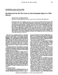
Based on economical and environmental considerations, it is necessary to apply efficient and suitable technology for CO2 separation with low operating cost and energy consumption. Up to now, there are several gas separation technologies being investigated for post-combustion capture, namely, (a) absorption, (b) adsorption, (c) cryogenic distillation, and (d) membrane separation (Figure 4) [39, 44]. Although various new methods were suggested for CO2 separation, Granite and Brien [45] reviewed some of the most novel methods for carbon dioxide separation from flue and fuel gas streams, such as use of electrochemical pumps and chemical looping for CO2 separation. 2.1. Absorption. Absorption stripping is an important technology for CO2 capture from fuel gas; in this technology desired component in mixed gases are dissolved in a solvent (bulk phase) [46]. The general scheme of this process is depicted in Figure 5. The flue gas (containing CO2 ) is cooled (between 318 and 323 K), and fed to the absorption column (scrubber) where the solvent absorbs CO2 . The CO2 -rich solution is fed into a heater to increase the temperature of solution, then to a stripper column to release the CO2 . The released CO2 is compressed, and the regenerated absorbent solution is cooled and recycled to the absorber column [47, 48]. Energy required for post-combustion CO2 capture is an important issue. Thus, recent studies suggest that reduction of the cost of this capture could be achieved by finding suitable solvents that could process larger amounts of CO2 for a given mass and require less energy for stripping stage [49, 50]. 2.1.1. Solvents. In absorption process, flue gas is contacted with a liquid “absorbent” (or “solvent”), and CO2 is absorbed by this solvent [21]. However, the absorbent should have a suitable capacity for CO2 absorption, high kinetic rate for CO2 absorption, negligible vapor pressure, and high chemical and thermal stability and should be harmless for labor persons [51–53]. The solvents used for CO2 absorption can be divided into two categories: physical and chemical solvents. Physical solvent processes use organic solvents to physically absorb acid gas components rather than reacting chemically, but chemical absorption depends on acid-base neutralization reactions using alkaline solvents [54, 55]. In the recent years, many studies have compared the performance of different solvents as listed in Table 2. (1) Alkanolamines. Between various solvent groups, alkanolamines group is the most important and more used for CO2 separation. A major problem in the usage of amines for CO2 absorption is equipment corrosion, so Albritton et al. [56] examined corrosion rate of various amine solvents and suggested corrosion rate could reduce in the following order: monoethanolamine (MEA) > 2-amino-2-methyl-1-propanol (AMP) > diethanolamine (DEA) > methyl diethanolamine (MDEA).
4
The Scientific World Journal
Chemical
MEA, caustic, ammonia solution
Physical
Selexol, Rectisol, fluorinated solvents
Physical
Alumina, zeolite, activated carbon
Chemical
CaO, MgO, Li2 ZrO3 , Li4 SiO4
Absorption
Adsorption CO2 separation and capture
Cryogenic Gas separation Membrane
Polyphenyleneoxide, polydimethylsiloxane
Gas absorption
Polypropylene
Ceramic membrane
Figure 4: Different technologies for CO2 separation [29].
Exhaust gas
Feed gas cooler Feed gas
Liquid storage tank
Condenser
CO2 product gas
Stripper Absorber
Heater
Cooler
Reboiler
Figure 5: Schematic diagram of CO2 absorption pilot plant.
On the other way, MEA can react more quickly with CO2 than MDEA, but MDEA has higher CO2 absorption capacity and requires lower energy to regenerate CO2 [39, 57, 58]. Thus, it can be concluded that MEA is one of the best amine solvents for CO2 separation. Idem et al. [59] reported substantial reduction in energy requirements and modest reduction in circulation rates for amine blends relative to the corresponding single amine system of similar total amine concentration. Wang et al. [57] found that when MEA and MDEA are mixed at the appropriate ratio, the energy consumption for CO2 regeneration is reduced significantly. Dave et al. [28] compared the performance of several amine solvents and ammonia solutions at various concentrations. They showed that 30 wt% AMP based process has the lowest overall energy requirement among the solvents considered in their study (30% MEA, 30% MDEA, 2.5% NH3 , and 5% NH3 ) [28, 60]. Knudsen et al. [61] studies showed that it is possible to run the post-combustion capture plant continuously while achieving roughly 90% CO2 separation levels and CASTOR-2 (blended amine solvents), operated in pilot scale with lower
steam requirement and liquid-to-gas ratio (L/G) than the conventional MEA solvent. Besides alkanolamines, carbonate-bicarbonate buffers and hindered amines are used in the bulk removal of CO2 owing to the low steam requirement for its regeneration. Mitsubishi Heavy Industries and Kansai Electric have employed other patented chemical solvents—strictly hindered amines called KS-1, KS-2, or KS-3. The regeneration heat of KS solvents is said to be ∼3 GJ/t CO2 , that is, 20% lower than that of MEA with ∼3.7 GJ/t CO2 [60, 64, 77]. Generally, the overall cost of amine absorption/stripping technology for CO2 capture process is 52–77 US$/ton CO2 [71]. (2) Amino Acid. Amino acids have the same functional groups as alkanolamines and can be expected to behave similarly towards CO2 but do not deteriorate in the presence of oxygen. Based on the results of tests, the aqueous potassium salts (composed of sarcosine and proline) are considered to be the most promising solvents. The most common amino acids used in the gas treating solvents are glycine, alanine, dimethyl
The Scientific World Journal
5
Table 2: Various solvents suggested for CO2 separation. Group of solvents
Advantage
Disadvantage
Application
Reference
Physical Dimethyl ether of polyethylene glycol (Selexol) Glycol Glycol carbonate
(i) Require low energy for regeneration (less than 20% of the value for chemical absorbent) (ii) Low vapor pressure, low toxicity, and less corrosive solvent
(i) Dependent on temperature and pressure; therefore they are not suitable for post-combustion process (ii) Low capacity for CO2 absorption
Natural gas sweetening Capturing CO2 and H2 S at higher concentration
[29, 39, 57, 62, 63]
Separating CO2 from other gases
Methanol (Rectisol)
CO2 removal from various streams
Fluorinated solvent
(i) CO2 removal from various streams (ii) Separating CO2 from other gases Chemical
Alkanolamines: monoethanolamine (MEA), diethanolamine (DEA), and methyl diethanolamine (MDEA)
(i) React rapidly (ii) High selectively (between acid and other gases) (iii) Reversible absorption process (iv) Inexpensive solvent
(i) Low CO2 loading capacity (ii) Solvent degradation in existence of SO2 and O2 in flue gas (concentrations must be Important for removing acidic less than 10 ppm and 1 ppm) components from gas streams (iii) High equipment corrosion rate (iv) High energy consumption
Amino acid and aqueous amino acid salt
(i) The possibility of adding a salt functional group. (ii) The nonvolatility of solvents (iii) Having high surface tension (iv) Having better resistance to degradation than other chemical solvents (v) Better performance than MEA of the same concentration for CO2 absorption
Decreased performance in the presence of oxygen
Suggested for CO2 separation from flue gases
[65, 67– 69]
Ammonia
(i) No degradation in the presence of SO2 and O2 in the flue gases (ii) No corrosion effect (iii) Require low energy to regeneration (1/3 that required with MEA) (iv) Low costs with aqueous ammonia, respectively, 15% and 20% less than with MEA
(i) Reversible at lower temperatures (not suitable for post-combustion) (ii) Production of solid products and their operating Suggested for CO2 separation problems from flue gases (iii) Explosion of dry CO2 -NH3 reaction in the high concentration of CO2 in the flue gas (explosive limit for NH3 gas is 15–28%)
[39, 70]
Ionic liquid (IL)
(i) Very low vapor pressure (ii) Good thermal stability (iii) High polarity (iv) Nontoxicity
Increased viscosity with CO2 absorption
Suggested for CO2 separation from flue gases
[71–74]
[58, 60, 61, 64–66]
6
The Scientific World Journal Table 2: Continued.
Group of solvents
Advantage
Disadvantage
Application
Aqueous piperazine (PZ)
(i) Fast absorption kinetics (CO2 absorption rate with aqueous PZ is more than double that of MEA) (ii) Low degradation rates for CO2 separation (iii) Negligible thermal degradation in concentrated PZ solutions (iv) Favorable equilibrium characteristics (v) Very low heat of absorption (10–15 kCal/mol CO2 ), 80–90% energy required for aqueous amine system
Lower oxidative degradation of concentrated PZ (i.e., 4 times slower than MEA in the presence of the combination of Fe2+ /Cr3+ /Ni2+ and Fe2+ /V5+ )
(i) Effective for treating syngas at high temperatures [29, 66, 75, (ii) Application of additional 76] amine promoters for natural gas treating and CO2 separation from flue gases
glycine, diethyl glycine, and a number of sterically hindered amino acids [65, 67, 68]. Results of many research groups showed that these solvents are suitable for application in membrane gas absorption units, because these solvents have better performance and degradation resistance than other chemical solvents [78]. Amino acid salts formed by neutralization of amino acids with an organic base such as amine showed better CO2 absorption potential than amino acid salts from neutralization of amino acid salts from an inorganic base such as potassium hydroxide [79, 80]. Aronu et al. [69] studied the performance of amino acids neutralized with 3(methylamino)propylamine (MAPA), glycine, 𝛽-alanine, and sarcosine. Their results indicated that sarcosine neutralized with MAPA has the best CO2 absorption performance. Its performance is also enhanced by promoting with excess MAPA [69]. (3) Ammonia. Since ammonia is a toxic gas, prevention of ammonia “slip” to the atmosphere is a necessity. Despite this disadvantage, chilled ammonia process (CAP) was used for CO2 separation (Figure 6). In the CAP, CO2 is absorbed in an ammoniated solution at a lower absorption temperature (275–283 K) that reduced ammonia emissions from the CAP absorber. Ammonium carbonate solution resulted in approximately 38% carbon regeneration compared to MEA solution [70, 81, 82]. (4) Aqueous Piperazine (PZ). Piperazine (PZ) is as an additive used for amine systems to improve kinetics of CO2 absorption, such as MDEA/PZ or MEA/PZ blends. Because PZ solubility in water is low, concentration of PZ is between 0.5 and 2.5 M. As indicated in Table 2, increasing the concentration of PZ in solution allows for increased solvent capacity and faster kinetic. The presence of potassium in solution increases the concentration of CO3 2− /HCO3 − in solution; therefore, solution has buffering property. These competing effects yield a maximum fraction of reactive species at potassium to piperazine ratio of 2 : 1 [75, 83, 84].
Reference
2.2. Adsorption. Adsorption operation can reduce energy and cost of the capture or separation of CO2 in postcombustion capture. To achieve this goal, it is necessary to find adsorbents with suitable properties. In general, CO2 adsorbent must have high selectivity and adsorption capacity and adequate adsorption/desorption kinetics, remain stable after several adsorption/desorption cycles, and possess good thermal and mechanical stability [51, 85–88]. The adsorbents used for CO2 separation placed into two main categories: physical and chemical adsorbents. 2.2.1. Chemical Adsorption. Chemisorption is a subclass of adsorption, driven by a chemical reaction occurring at the exposed surface. Adsorption capacities of different chemical adsorbents are summarized in Table 3. A wide range of metals have been studied including [89] (i) metal oxides: CaO, MgO, (ii) metal salts from alkali metal compounds: lithium silicate, lithium zirconate to alkaline earth metal compounds (i.e., magnesium oxide and calcium oxide), (iii) hydrotalcites and double salts. In general, one mole of metal compound can react with one mole of CO2 with a reversible reaction. The process consists of a series of cycles where metal oxides (such as CaO) at 923 K are transformed into metal carbonates form (such as CaCO3 ) at 1123 K in a carbonation reactor to regenerate the sorbent and produce a concentrated stream of CO2 suitable for storage [90, 91]. Considerable attention was paid to calcium oxide (CaO) as it has a high CO2 adsorption capacity and high raw material availability (e.g., limestone) at a low cost. Lithium salts was recorded a good performance in CO2 adsorption, but it gained less focus due to its high production cost. Although double salts can be easily regenerated due to low energy requirement, their stability has not been investigated [93, 96].
The Scientific World Journal
7
Ammonia removal
HCl
WT3
HX7
WT1
CM1
WT2
A
CM2
CM3
CO2 compression
CH5
Chilmine Y
AC2 PR2
PIPE
FN2
AC3
AC4
AC4
PM8
PR3 PM6 HX1
HX2
HX3
PR1
FN1
CC1 A
AC1
PM1
CH2 CC3
CC2 A
PM2
H2 O
HX4
CH1 FGD
PM7
NH3 HX6
A
PM3
CH4 HX5 AB
HC PM4
PM5
Absorption/ regeneration/ gas wash
Steam
CH3 RG
RB Condensate
Exhausts chilling
Figure 6: Schematic layout of CO2 separation block based on the chilled ammonia process [92]. Table 3: Adsorption capacity of chemical adsorbents for post-combustion CO2 . Sorbent Mesoporous (MgO) CaO nanopods CaO derived from nanosized CaCO3 CaO-MgAl2 O4 (spinel nanoparticles) Nano CaO/Al2 O3 Lithium silicate nanoparticles Nanocrystalline Li2 ZrO3 particles CaO/Al2 O3 Lithium silicate Lithium zirconate Lithium orthosilicate Calcium oxide Magnesium hydroxide Mesoporous magnesium oxide Lithium Silicate nano particles HTI-HNa
Operating temperature (K)
Operating pressure (kPa)
CO2 capture capacity (mol CO2 /kg sorbent)
Regeneration cycles, 𝑛
298 873 923 923 923 883 843 923 993 673 873 873 473 373 873 573
101 101 101 101 101 101 101 101 n.a. 100 100 100 1034 100 101 134
1.8 17.5 16.7 9.1 6.0 5.77 6.1 6.02 8.18 5.0 6.13 17.3 3.0 2.27 5 1.109
3 50 100 65 15 n.a. 8 n.a. n.a. n.a. n.a. n.a. n.a. n.a. n.a. 50
The reaction of CO2 adsorption with Li2 ZrO3 is reversible in the temperature range of 723–863 K. The capacity of lithium silicate (8.2 moL CO2 /kg sorbent at 993 K) is larger than that of lithium zirconate (4.85 moL/kg sorbent) [17]. Hydrotalcite (HT) contains layered structure with positively charged cations balanced by negatively charged anions [97, 98]. Adsorption and final capacity of different adsorption/desorption cycles are listed in Table 3. One way for improving CO2 adsorption efficiency is application of nanomaterials. Different nano-materials can be used for CO2 separation (Table 3). However, nanomaterials always have high production cost with complicated synthesis process such as carbon nanotubes and graphite nanoplatelets [99, 100]. The main disadvantage of chemical adsorbents is difficult regeneration process, and application of these adsorbents needs more studies for finding new adsorbents [88, 95]. 2.2.2. Physical Adsorption. Physisorption, also called physical adsorption, is a process in which the electronic structure of
CO2 capture capacity remained Reference after 𝑛 cycles (%) [93] 100 [94] 61.1 [93] 22.2 [93] 84.6 [93] 61.7 [93] n.a. [93] 100 [93] n.a. [17] n.a. [93] n.a. [93] n.a. [93] n.a. [93] n.a. [93] n.a. [95] n.a. [93] 93.3
the atom or molecule is barely perturbed upon adsorption. If the CO2 adsorption capacity of solid adsorbents reaches 3 mmoL/g, the required energy for adsorption will be less than 30–50% energy for absorption with optimum aqueous MEA [101]. The major physical adsorbents suggested for CO2 adsorption include activated carbons and inorganic porous materials such as zeolites [102, 103]. The adsorption capacities of various physical adsorbents are summarized in Table 4. Coal is one of the adsorbents being suggested for CO2 separation. The total amount of CO2 that can be adsorbed in coal depends on its porosity, ash, and affinity for this molecule [111, 112]. Sakurovs et al. [113] showed that the ratio of maximum sorption capacity between CO2 and methane decreases with increasing carbon content. The average CO2 /CH4 sorption ratio is higher for moistureequilibrated coal and decreases with increasing coal rank (1.4 for high rank coals to 2.2 for low rank coals) [114–116]. Activated carbon (AC) has a number of attractive characteristics, such as its high adsorption capacity, high hydrophobicity, low cost, and low energy requirement for regeneration
8
The Scientific World Journal
Table 4: Adsorption capacity of physical adsorbents for post-combustion CO2 . Sorbent Activated carbon AC (4% KOH) AC (EDA + EtOH) AC (4% KOH + EDA + EtOH) NiO-ACs 13X 5A 4A WEG-592 APG-II Na-Y Na-X NaKA NaX-h NaX-h Na-X-c Na-X-c Cs-X-h Cs-X-h Cs-X-c Cs-X-c MCM-41 MCM-41 (DEA) MCM-41 (50% PEI) Activated carbon MCM-41 (50% PEI) “molecular basket” PE-MCM-41 PE-MCM-41 (TRI) PE-MCM-41 (DEA) MCM-48 MCM-48 (APTS) MCM-41 Molecular basket’ MCM-41 (50% PEI) PE-MCM-41 (TRI) PE-MCM-41 (DEA) MWNT Unmodified [(Cu3 (btc)2 ]∗ CNT@ (Cu3 (btc)2 ) MIL-101∗∗ MWCNT@MIL-101 MOF-2 MOF-177 Zr-MOFs Ca-Al LDH with ClO4 −
Operating temperature (K)
Operating pressure (kPa)
CO2 capture capacity (mol CO2 /kg sorbent)
Regeneration cycles, 𝑛
303 303 303 303 298 393 393 393 393 393 273 373 373 323 373 323 373 323 373 323 373 298 348 348 303
110 30 30 30 101 15.198 15.198 15.198 15.198 15.198 10.132 101.32 101.32 101.32 101.32 101.32 101.32 101.32 101.32 101.32 101.32 100 100 100 30
1.58 0.55 0.53 0.64 2.227 0.7 0.38 0.5 0.6 0.38 4.9 1.24 3.88 2.52 1.37 2.14 1.41 2.42 1.48 1.76 1.15 0.62 1.26 2.52 0.35
n.a. n.a. n.a. n.a. n.a. n.a. n.a. n.a. n.a. n.a. n.a. 2 — 2 2 2 2 2 2 2 n.a. n.a. n.a. n.a. n.a.
348
100
2.95
n.a.
n.a.
[93]
298 298 348 298 298 298
100 100 100 100 100 100
0.50 2.85 2.36 0.033 0.639 0.62
n.a. n.a. n.a. n.a. n.a. n.a.
n.a. n.a. n.a. n.a. n.a. n.a.
[93] [93] [93] [93] [93] [93]
348
100
2.5
8
96.0
[93]
298 298 303 298 298 298 298 298 298 273 406
100 100 101 1818 1818 1010 1010 4545 4545 988 1
1.8 2.9 1.7 6.7 13.52 0.84 1.35 3.20 33.5 8.1 3.55
10 7 20 n.a. n.a. n.a. n.a. n.a. n.a. n.a. n.a.
94.4 96.6 n.a. n.a. n.a. n.a. n.a. n.a. n.a. n.a. n.a.
[93] [93] [4, 93] [101] [101] [101] [101] [107] [107] [107] [108]
CO2 capture capacity Reference remained after 𝑛 cycles (%) [93] n.a. [93] n.a. [93] n.a. [45, 70, 79] n.a. [104] n.a. [105] n.a. [105, 106] n.a. [105] n.a. [105] n.a. [105] n.a. [105] n.a. [105] n.a. [105] n.a. [105] n.a. [105] n.a. [105] n.a. [105] n.a. [105] n.a. [105] n.a. [105] n.a. [105] n.a. [93] n.a. [93] n.a. [93] n.a. [93] n.a.
The Scientific World Journal
9 Table 4: Continued.
Sorbent Pd-GNP nanocomposite f-GNP Pd-GNP nanocomposite f-GNP Pd-GNP nanocomposite f-GNP Ceria-based oxides doped with 5% gallium (III) Amine modified layered double hydroxides (LDHs)
Operating temperature (K)
Operating pressure (kPa)
CO2 capture capacity (mol CO2 /kg sorbent)
Regeneration cycles, 𝑛
298 298 298 298 298 298
1111 1111 1111 1111 1111 1111
5.1 4.3 4.5 3.8 4.1 3.3
n.a. n.a. n.a. n.a. n.a. n.a.
298
101
0.282
n.a.
n.a.
[110]
298–353
101
0.74–1.75
n.a.
n.a.
[108]
CO2 capture capacity Reference remained after 𝑛 cycles (%) [109] n.a. [109] n.a. [109] n.a. [109] n.a. [109] n.a. [109] n.a.
∗
Cu3 (btc)2 ; btc: 1,3,5-benzene-tricarboxylate. MIL-101 or Cr3 (F,OH)(H2 O)2 O[(O2 C)C6 H4 (CO2 )]3 ⋅ 𝑛H2 O (𝑛 ≈ 25) is one of the metal organic frameworks with Lewis acid sites that can be activated by removal of guest water molecules.
∗∗
[117–119]. Activated carbons are inexpensive, insensitive to moisture, and easy for regeneration. These adsorbents have well developed micro- and mesopore structures that are suitable for high CO2 adsorption capacity at ambient pressure [120–122]. However, activated carbon CO2 /N2 selectivities (ca. 10) are relatively low; zeolitic materials offer CO2 /N2 selectivities 5–10 times greater than those of carbonaceous materials. The adsorption capacity and selectivity of zeolites are largely affected by their size, porous diameter, charge density, and chemical composition of cations in their porous structures. The average value of heat adsorption on zeolites (36 kJ/moL) is larger than for activated carbon (30 kJ/moL), confirming the mentioned affirmation. Moreover, activated carbon can be regenerated easily and completely. Also its capacity did not decay after 10 consecutive processes cycles [122–124]. Due to the increase in cost of raw materials, growing research interest has been focused on producing AC from agricultural wastes. Some of the agricultural wastes include the shells and stones of fruits, wastes resulting from the production of cereals, bagasse, and coir pith [100]. Rosas et al. [125] prepared hemp-derived AC monolith by phosphoric acid activation. The activated carbons from hemp stem are microporous materials and therefore suitable ones for hydrogen storage and CO2 capture [126]. Siriwardane et al. [127] studied CO2 adsorption on the molecular sieve 13X, 4A and activated carbon. The molecular sieve 13X showed better CO2 separation than molecular sieve 4A. At lower pressures ( CO2 > NO > N2 on both zeolites (5A and 13X). Comparing two different adsorbents, the better separation efficiency can be achieved by 5A zeolite [145]. Zhang et al. [130] focused on the effect of water vapour on the pressure/vacuum swing adsorption process. The selected adsorbents in this study were CDX (an alumina/zeolite blend), alumina, and 13X zeolite as these adsorbents are either the prelayer for water adsorption or the main CO2 adsorption layer in the packed bed [130]. Metal-organic framework (MOF) materials are crystalline with two- or three-dimensional porous structures that can be synthesised with many of the functional capabilities of zeolites. Several MOFs have been proposed as adsorbents for CO2 separation processes, and among these Cu-BTC [polymeric copper (II) benzene-1,3,5-tricarboxylate] has proved to be dedicated with CO2 adsorption performances that are higher than those of typical adsorbents such as 13X zeolite [105, 107, 146, 147]. The MCM-41 material is one of the mesoporous products which was prepared by the hydrothermal method from mobil composition of matter (MCM) powders. Lu et al. [148] showed that mesoporous silica spherical particles (MSPs) can be synthesized using low-cost Na2 SiO3 thus they can be cost-effective adsorbents for CO2 separation from flue gas [149, 150]. Layered double hydroxides (LDHs) have general formula 𝑔− II [M1−𝑥 MIII 𝑥 (OH)2 ][X𝑥/C ⋅ 𝑛H2 O] with 𝑥 typically in the range between 0.10 and 0.33. These materials can be readily and inexpensively synthesized with the desired characteristics for a particular application such as CO2 adsorption [108, 151]. 2.2.3. Adsorbent Modification. The role of CO2 as a weak Lewis acid is well established. Because of the nature of CO2 , the surface of the physical adsorbents can be modified by adding basic groups, such as amine groups and metal oxides to improve CO2 adsorption capacity or selectivity [152–154]. Three different methods for the production of these adsorbents were investigated: activation with CO2 , heat treatment with ammonia gas (amination and ammoxidation), and heat treatment with polyethylenimine (PEI). However, it has been suggested that amine modification can produce better and cheaper CO2 adsorbents [24, 104, 155, 156]. Xu et al. [157, 158] designed selective “molecular basket” by grafting polyethylenimine (PEI) uniformly on MCM-41. CO2 adsorption capacity of the adsorbent was 24 times higher than MCM-41 and 2 times higher than PEI [93]. The addition of ammonium hydroxide resulted in the Zr-MOF with a slight lower adsorption of CO2 and CH4 ; however, the selectivity of CO2 /CH4 is significantly enhanced [159, 160]. Results of Abid et al. [107] showed that the selectivity of CO2 /CH4 on Zr-MOF is between 2.2 and 3.8, while for Zr-MOF-NH4 selectivity is between 2.6 and 4.3. A nitrogen-rich carbon with a hierarchical micro-mesopore structure exhibited a high CO2 adsorption capacity (141 mg/g at 298 K, 1 atm), excellent separation efficiency (CO2 /N2 selectivity is ca. 32), and excellent stability [161].
The Scientific World Journal Plaza et al. [162] results showed that CO2 adsorption capacity of the DETA-impregnated alumina (≥2.3 mmoL/g) exhibited is the highest. Amine modified layered double hydroxides (LDHs) have been prepared by several different methods. Park et al. [163] used dodecyl sulfate (DS) intercalated LDH as precursor and added (3-aminopropyl) triethoxysilane (APTS) together with N-cetyl-N,N,N-trimethylammonium bromide (CTAB) [164]. The highest adsorption capacity of amine modified LDHs for CO2 was achieved at 1.75 mmoL/g by MgAl N3 at 353 K and 1 bar. According to data in Table 4, this adsorbent has high CO2 capacity at high temperature; therefore, this adsorbent is suitable for post-combustion CO2 capture [108]. Wang et al. [114] reported that porous carbons with welldeveloped pore structures were directly prepared from a weak acid cation exchange resin (CER) by the carbonization of a mixture with Mg acetate in different ratios [108]. The main parameters of this adsorbent (such as CO2 capacity) are indicated in Table 4. Shafeeyan et al. [165] prepared different adsorbents based on the central composite design (CCD) with three independent variables (i.e., amination temperature, amination time, and the use of preheat treated (HTA) or preoxidized (OXA) sorbent as the starting material). They demonstrated that the optimum condition for obtaining an efficient CO2 adsorbent is using a preoxidized sorbent and amination at 698 K for 2.1 h [165]. Table 4 compares CO2 adsorption capacities and stability of different absorbents, which were studied for postcombustion CO2 capture. 2.2.4. Different Cycles for CO2 Adsorption. Five different regeneration strategies were demonstrated in a single-bed CO2 adsorption unit: pressure swing adsorption (PSA), temperature swing adsorption (TSA), vacuum swing adsorption (VSA), electric swing adsorption (ESA), and a combination of vacuum and temperature swing adsorption (VTSA). The difference between these technologies is based on the strategy for regeneration of adsorbent after the adsorption step (Figure 7). In PSA applications, the pressure of the bed is reduced. VSA is preferred to the special PSA application where the desorption pressure is below atmospheric, whereas in TSA, the temperature is raised while pressure is maintained approximately constant, and in ESA the solid is heated by the Joule effect [166–169]. For the single-bed cycle configurations, the productivity and CO2 recovery followed the sequence: ESA < TSA < PSA < VSA < VTSA.
(1)
The performances of PSA, TSA, VSA, VTSA, and ESA processes for CO2 separation are reported in Table 5. Since application of adsorption process for CO2 capture in industrial scale is very important, in recent years some researches have been focused on this area; for example, Lucas et al. [170] studied the scale-up CO2 adsorption with activated carbon. 2.3. Cryogenic Distillation. Cryogenic method utilized low temperatures for condensation, separation, and purification
The Scientific World Journal
11
bed
Adsorbent Condensate
Flue gas
Adsorbent bed
Adsorbed gas
Adsorbent bed
Adsorbent bed
Steam
Flue gas
(a)
(b)
Adsorbed gas
−
Adsorbent bed
Adsorbent bed
+
Adsorbent bed
Adsorbent bed
Vacuum pump + −
Flue gas
Flue gas (c)
(d)
Figure 7: Schematic diagrams of various adsorption cycles, (a) TSA, (b) PSA, (c) VSA, and (d) ESA; thin lines indicated operation streams in regenerated step.
Table 5: Comparison between several adsorption cycles for CO2 separation process [166]. Process PSA TSA TSA ESA VSA VSA 3-bed VSA PSA/VSA PSA/VSA VPSA VPSA PTSA 2-bed-2-step PSA VTSA
CO2 CO2 feed molar fraction CO2 (%) (other gases present) purity (%) recovery (%) 13 (O2 ) 10 17 10 15 17 12 20 15 (H2 O) 17 16 (O2 ) 10
99.5 95 n.a. 23.33 90 n.a. 90–95 58–63 59 99.5–99.8 99 99
69 81 40 92.57 90 87 60–70 70–75 87 34–69 53–70 90
n.a.
18
90
17
n.a.
97
of CO2 from flue gases (freezing point of pure CO2 is 195.5 K at atmospheric pressure). Therefore, under the cryogenic separation process, the components can be separated by
a series of compression, cooling, and expansion steps. It enables direct production of liquid CO2 that can be stored or sequestered at high pressure via liquid pumping [171–173]. The advantages of this technology can be summarized as follows [6, 8, 174]. (1) Liquid CO2 is directly produced, thus making it relatively easy to store or send for enhanced oil recovery. (2) This technology is relatively straightforward, involving no solvents or other components. (3) The cryogenic separation can be easy scaled-up to industrial-scale utilization. The major disadvantages of this process are the large amount of energy required to provide the refrigeration and the CO2 solidification under a low temperature, which causes several operational problems [176–178]. Therefore, more studies are required for reducing the cost of cryogenic separation. Clodic et al. [179] indicated that the energy requirement for cryogenic process was in the range of 541–1119 kJ/kg CO2 . Zanganeh et al. [6] have constructed a pilot-scale CO2 capture and compression unit (CO2 CCU) that can separate CO2 as liquid phase from the flue gas of oxy-fuel combustion. Their results showed that cryogenic is the most cost effective when
12
The Scientific World Journal S15 (liquid CO2 ) S6 (liquid CO2 )
External cold energy
External cold energy S10 (liquid CO2 ) S11 (liquid CO2 )
C1 Mixture S1
S2
H1
S3
H2
Sep1
S4
C2
S7
S5 (liquid CO2 ) P1
Step 1
H3
S8
H4 P2
Sep2 S9 (liquid CO2 )
Step 2 C1 (intercooled H5
S14 (purge gas)
T
S12 (purge gas)
S13 (purge gas)
Figure 8: Novel CO2 cryogenic liquefaction and separation system [175].
the feed gas is available at high pressure. Therefore, cryogenic is not suitable for post-combustion and it is well effective for separation stream with high CO2 concentration such as oxyfuel combustion. Amann et al. [180] reported that conversion of O2 /CO2 cycle was more efficient than amine scrubbing but more difficult to implement because of the specific gas turbine. Xu et al. [175] studied a novel CO2 cryogenic liquefaction and separation system (Figure 8). In this system, two-stage compression, two-stage refrigeration, two-stage separation, and sufficient recovery of cryogenic energy were adopted. The energy consumption for CO2 recovery is only 0.395 MJ/kg CO2 . Furthermore, this CO2 cryogenic separation system is more suitable for gas mixtures with high initial pressure and high CO2 concentration [175]. Song et al. [181] developed a novel cryogenic CO2 capture system based on Stirling coolers (SC). The operation of Stirling cooler contains four processes: isothermal expansion, refrigeration under a constant volume, isothermal compression, and heating under a constant volume condition. This novel cryogenic system can condense and separate H2 O and CO2 from flue gas. Their results showed that under the optimal temperature and flow rate, CO2 recovery of the cryogenic process can reach 96% with 1.5 MJ/kg CO2 energy consumption. Tuinier et al. [182] exploited a novel cryogenic CO2 capture process using dynamically operated packed beds (Figure 9). By the developed process, above 99% of CO2 could be recovered from a flue gas containing 10 vol.% CO2 and 1 vol.% H2 O with 1.8 MJ/kg CO2 energy consumption [181]. Chiesa et al. [183] proposed an advanced cycle that a molten carbonate fuel cell (MCFC) was used to separate the CO2 from the gas turbine exhaust of a natural gas fired combined cycle power plant. In this cycle, gas turbine flue gases actually are used as cathode feeding for MCFC. While CO2 is moved from the cathode to anode side, concentrate CO2 in the anode exhaust. Then the CO2 is concentrated on the anode side of MCFC allowing to easily treat this
spent fuel stream in a cryogenic process to split combustible species (routed back to gas turbine combustor) from the CO2 addressed to storage (Figure 10) [183]. 2.4. Membrane Separation. The membrane separation method is a continuous, steady-state, clean and simple process, and ideal as an energy-saving method for CO2 recovery. Gas separation using membranes is a pressure-driven process. Due to the low pressure of flue gases, driving force is too low for membrane processes in post-combustion (low pressure and low CO2 concentration). Membrane processes offer increased separation performances when CO2 concentration in the feed mixture increases [184–186]. Membrane separation processes have several advantages over other CO2 separation technologies. The required process equipment is very simple, compact, relatively easy to operate and control, clear process and easy to scale up [187, 188]. The energy required for the recovery of CO2 by membrane processes depends on the target purity, flue gas composition, and membrane selectivity for CO2 . Howevre membrane processes require too much energy for postcombustion CO2 capture; therefore, low partial pressure of CO2 in the flue gas is a possible disadvantage for the application of membranes. Another disadvantage of membrane process is that the membrane selectivity for the separation of CO2 from SO𝑥 and NO𝑥 is very low. Membrane process is not useful for high flow rate applications [189–191]. Therefore, the useful membrane for post-combustion CO2 capture should have some specification such as [192, 193] (i) high CO2 permeability, (ii) high selectivity for CO2 separatation from flue gases, (iii) high thermal and chemical stability, (iv) resistant to plasticisation, (v) resistant to aging, (vi) cost effective, (vii) low production cost for different membrane modules.
The Scientific World Journal
13
N2
Flue gas, in
CO2 , in
TC , in
TCO 2 T0
TH2 O TR , in
∗ TCO 2
TCO 2
TR , in
TH2 O ∗ TCO 2
T0 Axial position
Axial position
Axial position t1 t2
TC , in Temperature
TH2 O
Temperature
TC , in Temperature
N2 , out
N2 , in
CO2 , out
t0 t1 t2
t0 t2
(a)
(b)
(c)
Figure 9: Schematic axial temperature and corresponding mass deposition profiles for the cryogenic; (a) capture, (b) recovery, and (c) cooling cycles [182]. Natural gas Sulfur removal
Condensate Air AC DC Cathode Anode Make-up water
CO2 to storage
Cryogenic CO2 separation
Figure 10: Plant layout showing the integration of the MCFC in a combined cycle, with cryogenic CO2 separation after oxygen combustion of the cell an anode exhaust [183].
Many efforts have been made to find new material with suitable properties (Table 6). Various groups of materials have been already proposed and experimentally investigated for post-combustion CO2 capture with membrane process. By modifying membrane their properties can be improved. For example, when amine functional groups are randomly dispersed in the silica matrix,
this membrane can separate CO2 with high selectivity. On the other hand, membrane structure can be modified by adding arginine salts [194–196]. 2.4.1. Inorganic Membranes. Based on structure, inorganic membranes can be classified into two categories: porous and
14
The Scientific World Journal
Table 6: Carbon dioxide and nitrogen gas permeability data for different membranes. Name Y (FAU) with 𝛼-A12 O3 support ZSM-5 (MFI) with 𝛼-A12 O3 support ZSM-5/polymeric silica Stainless steel support infiltrated with a eutectic molten carbonate mixture (Li/Na/K) Y-type NaY Li(20%)Y K(30%)Y K(62%)Y Rb(38%)Y Cs(32%)Y 20% K2 CO3 , 80% Li2 CO3 MCM-48 PEI-modified MCM-48 Chitosan Swollen chitosan Arginine salt-chitosan Polytrimethyl-prop-1-ynyl-silane Poly-3,3-dimethyl-but-1-yne Poly-1-(dimethyltrimethylsilanylmethyl-silanyl)propyne Poly-1-[dimethyl-(2trimethylsilanyl-ethyl)-silanyl]propyne Polytrimethyl-(2-prop-1-ynylphenyl)-silane Poly-1-prop-1-ynyl-2trifluoromethyl-benzene Poly-dec-2-yne Poly-1-chloro-dec-1-yne Poly-1-chloro-oct-1-yne Poly-1-chloro-hex-1-yne Polyhexyl-dimethyl-prop-1-ynylsilane Polytrimethyl-(1-pentyl-prop-2ynyl)-silane Polyhexyl-dimethyl-(1-propylprop-2-ynyl)-silane Polyprop-1-ynyl-benzene Polybut-1-ynyl-benzene Polyoct-1-ynyl-benzene Polychloroethynyl-benzene
Feed pressure (atm) n.a.
Temperature 𝑃∗ (CO2 ) (K) (barrer) Ion-exchanged zeolites membrane 308 n.a.
𝑃∗ (N2 ) (barrer)
𝛼 (CO2 /N2 )
Reference
n.a.
139
[197]
3
[197]
n.a.
n.a
n.a.
n.a.
n.a.
373
1140
n.a.
n.a.
923
7780
n.a.
16
[199]
n.a. n.a. n.a. n.a. n.a. n.a. n.a. n.a. n.a. n.a. n.a. n.a. n.a.
5 5 3 9 6 3 2 4 0.8 80 100 250 852
[200] [200] [200] [200] [200] [200] [200] [199] [189] [201] [192] [192] [194]
1800 43
10.6 13.0
[193] [193]
n.a. n.a. n.a. n.a. n.a. n.a. n.a. n.a. n.a. n.a. 1.75 1.5 1.5 n.a. n.a.
303–403 35900–89800 313 359000 308 210000 308 269000 313 150000 313 150000 313 59900 798 2990 n.a. 10200 363 14100 295 100 383 482 383 1500 Polyacetylene 298 19000 298 560
[198]
n.a.
298
310
21
14.8
[193]
n.a.
298
150
14
10.7
[193]
n.a.
298
290
24
12.1
[193]
n.a.
298
130
7.3
17.8
[193]
n.a. n.a. n.a. n.a.
298 298 298 298
130 170 130 180
14 16 11 10
9.3 10.6 11.8 18
[193] [193] [193] [193]
n.a.
298
71
4.3
16.5
[193]
n.a.
298
120
8.7
13.8
[193]
n.a.
298
70
6.3
11.1
[193]
n.a. n.a. n.a. n.a.
298 298 298 298
25 40 48 23
2.2 4.5 5.5 1.0
11.4 8.9 8.7 23.0
[193] [193] [193] [193]
The Scientific World Journal
15
Table 6: Continued. Name Poly-1-ethynyl-2-methyl-benzene Polydimethyl-phenyl-(1-propylprop-2-ynyl)-silane
Feed pressure (atm)
Temperature (K)
𝑃∗ (CO2 ) (barrer)
𝑃∗ (N2 ) (barrer)
𝛼 (CO2 /N2 )
Reference
n.a.
298
15
3.0
5.0
[193]
n.a.
298
54
2.5
21.6
[193]
2.18 1.37 2.39 1.70
11.6 13.5 12.32 12.6
[193] [193] [193] [193]
n.a. n.a. n.a. n.a. n.a.
50 80 145 230 53
[202] [203] [204] [184] [143]
n.a. n.a.
51 56
[152] [152]
6FPT-6FBPA 6FPT-BPA 1.0 35 6FPPy-6FBPA 6FPPy-BPA
1.0 1.0 1.0 1.0
Polarix PAAM-PVA/PS PVAm/PVA blend PEI/PVA PDMA/PS
2.0 10 1.45 n.a. 2
PA12 PA6 Polyethyleneimine/polyvinyl butyral Poly[(2-N,N-dimethyl) aminoethyl methacrylate] Poly(vinylbenzyltrimethyl ammonium fluoride) Polyethyleneimine/poly(vinyl alcohol) PEI/PDMS/PEBA1657/PDMS BPA/IA BPA/tBIA HFBPA/IA HFBPA/tBIA PhTh/IA PhTh/tBIA FBP/IA FBP/tBIA TBBPA/IA TBBPA/tBIA TBHFBPA/IA TBHFBPA/tBIA TBPhTh/IA TBPhTh/tBIA TBFBP/IA TBFBP/tBIA DMBPA/IA DMBPA/Tbia TMBPA/IA TMBPA/tBIA DiisoBPA/IA
10 10
Polyarylene ether 308 25.29 308 18.53 308 29.46 308 21.44 Fixed site carrier membrane (FSCM) 303 107 298 2.4 × 10⁵ 298 2.12 × 10⁶ 298 104 296 3 × 10⁵ Polyamine 308 120 308 66
0.132
318
380
n.a.
32
[193]
0.237
298
370
n.a.
111
[193]
0.224
296
113
n.a.
983
[193]
0.355
298
650
n.a.
235
[193]
n.a.
64
[205]
0.24 1.20 1.11 3.88 0.28 1.09 0.57 1.93 0.18 0.90 1.07 4.47 0.29 1.28 0.70 2.94 0.063 0.39 0.58 2.52 0.27
22.5 20.2 17.2 14.7 24.1 21.8 12.4 19.1 27.4 23.9 23.9 19.0 28.8 23.9 29.1 23.6 19.7 20.5 20.7 17.7 19.1
[193] [193] [193] [193] [193] [193] [193] [193] [193] [193] [193] [193] [193] [193] [193] [193] [193] [193] [193] [193] [193]
5 10 10 10 10 10 10 10 10 10 10 10 10 10 10 10 10 10 10 10 10 10
298 Polyarylate 308 308 308 308 308 308 308 308 308 308 308 308 308 308 308 308 308 308 308 308 308
1.57 × 10 5.4 24.2 19.1 56.9 6.74 23.8 12.4 36.8 4.93 21.5 25.6 85.1 8.34 30.6 20.4 69.5 1.24 8.0 12.0 44.6 5.16
6
16
The Scientific World Journal
Table 6: Continued. Name DiisoBPA/tBIA DBDMBPA/IA PhAnth/IA PhAnth/tBIA FBP/IA FBP/tBIA PC TMPC TCPC TBPC HFPC TMHFPC NBPC PCZ PC-AP FBPC PEO PEO PEO-PBT EO/EM/AGE (80/20/2) EO/EM/AGE (77/23/2.3) EO/EM/AGE (96/4/2.5)
Feed pressure (atm) 10 10 10 10 10 10 1–10 1–10 1 1 10 10 10 10 2 2 7.8 4.4–14.6 n.a. n.a. n.a. n.a.
Temperature (K)
𝑃∗ (CO2 ) (barrer)
308 16.1 308 5.45 308 9.0 308 25.9 308 12.4 308 36.8 Polycarbonates 308 6.0–6.8 308 17.58–18.6 308 6.66 308 4.23 308 24 308 111 308 9.1 308 2.2 308 9.48 308 15.1 Polyethylene oxide 298 8.1 308–318 13–52 308 120 308 773 308 680 308 580 Polyimides 308 186 308 11.8 308 6.12 308 1.14–2.7
Amine modified polyimide PMDA-BAPHF PMDA-3BAPHF PMDA-4,4 -ODA
0.368 6.8 6.8 6.8–10
PMDA-3,3 -ODA
6.8–10
308
0.50–3.55
PMDA-MDA PMDA-IPDA PMDA-BAPHF PMDA-BATPHF BPDA-BAHF BPDA-mTrMPD BTDA-4,4-ODA BTDA-BAPHF BTDA-BAHF BTDA-mTrMPD BTDA-BAFL PI oMeCat-durene mMeCat-durene DMeCat-durene
10 10 10 10 1–10 10 10 10 10 10 1 10 1 1 1
308 308 308 308 298–308 308 308 308 308 308 298 308 303 303 303
4.03 29.7 17.6 24.6 23–27.7 137 0.625 4.37 10.1 30.9 15 2.00 27 20 63
𝑃∗ (N2 ) (barrer)
𝛼 (CO2 /N2 )
Reference
1.08 0.22 0.36 1.35 0.57 1.93
14.9 24.8 25 19.2 21.8 19.1
[193] [193] [193] [193] [193] [193]
0.289–0.32 1.0 0.36 0.182 1.6 7.4 0.47 0.105 0.361 0.592
21 18.6 18.5 23.2 15.0 15.0 19.4 21.0 26.3 25.5
[193] [193] [193] [193] [193] [193] [193] [193] [193] [193]
0.07 0.24–1 2 16.8 15.5 12.1
140 55 60 46 44 48
[193] [193] [193] [193] [193] [193]
n.a. 0.66 0.29 0.049–0.1 0.018– 0.145 0.20 1.50 0.943 1.50 0.6–1.39 8.42 0.0236 0.195 0.45 1.55 0.39 0.063 0.83 0.59 2.05
38 17.8 21.1 23.3
[193] [193] [193] [193]
24.5–27.8
[193]
20.2 19.8 18.7 16.4 19.9–37.7 16.3 26.5 22.4 22.4 19.9 38.5 31.7 33 34 31
[193] [193] [193] [193] [193] [193] [193] [193] [193] [193] [193] [193] [193] [193] [193]
The Scientific World Journal
17
Table 6: Continued. Name mtBuCat-durene oMeptBuCat-durene TMeCat-durene mMetCat-MDA mtBuCat-MDA TMeCat-MDA TMeCat-TMB DBuCat-TMB mtBuCat-DMOB TMeCat-6FiPDA 6F TMMPD IMDDM ODA Matrimid 5218 6FDA-pPDA 6FDA-pDiMPDA 6FDA-durene 6FDA-durene 6FDA-mPDA 6FDA-mMPDA 6FDA-mTrMPDA 6FDA-DATr 6FDA-DBTF 6FDA-PHDoeP 6FDA-PEPE 6FDA-PBEPE 6FDA-PMeaP 6FDA-3,4 ODA 6FDA-APAP 6FDA-pp ODA 6FDA-BAPHF 6FDA-BATPHF 6FDA-BAHF 6FDA-1,5-NDA 6FDA-durene 24 h amidation 6FDA-durene/mPDA (50/50) 6FDA-durene/mPDA (50/50) 4 h amidation 6FDA-durene/mPDA (50/50) 6 h amidation 6FDA-durene/mPDA (50/50) 12 h amidation
Feed pressure (atm) 1 1 1 1 1 1 1 1 1 1 3 3 3 3 10 10 10 10 10 6.8–10 6.8–10 10 6.8 6.8 6.8 6.8 6.8 6.8 10 10 10 10 10 10 10 10 10
Temperature (K)
𝑃∗ (CO2 ) (barrer)
303 71 303 67 303 200 303 22 303 63 303 110 303 39 303 95 303 6.7 303 54 n.a. 114 n.a. 600 n.a. 196 n.a. 25 308 6.5 6FDA-based polyimides 308 15.3 303 42.7 308 440 303 456 308 8.23–9.20 303 40.1–42.5 308 431 303 28.63 308 21.64 303 8.59 308 6.88 303 2.50 308 2.41 303 6.11 308 10.7 303 16.7 308 19.1 303 22.8 308 51.2 308 23 n.a. 11.6 n.a. 84.6
𝑃∗ (N2 ) (barrer)
𝛼 (CO2 /N2 )
Reference
2.55 2.5 8.1 0.65 2.2 3.8 1.2 4.9 0.21 1.9 5.8 35.1 10.8 0.97 0.25
28 27 25 34 29 30 33 19 32 28 19.6 17.1 18.1 25.8 25.6
[193] [193] [193] [193] [193] [193] [193] [193] [193] [193] [193] [193] [193] [193] [193]
0.80 2.67 35.60 35.50 0.36–0.447 2.12–2.24 31.6 1.31 1.17 4.50 0.255 0.099 0.086 0.259 0.473 0.733 0.981 1.30 3.11 1.1 1.33 5.18
19.12 16.0 12.4 12.85 20.6–22.7 17.9–20.1 13.6 21.9 18.5 1.91 27.0 25.3 28.0 23.6 22.6 22.8 19.5 17.5 16.5 21 8.75 16.4
[193] [193] [193] [193] [193] [193] [193] [193] [193] [193] [193] [193] [193] [193] [193] [193] [193] [193] [193] [193] [193] [193]
10
n.a.
54.9
3.38
16.2
[193]
10
n.a.
49.1
3.27
15.0
[193]
10
n.a.
46.0
2.94
15.6
[193]
18
The Scientific World Journal
Table 6: Continued. Name
Feed pressure (atm)
Temperature (K)
𝑃∗ (CO2 ) (barrer)
𝑃∗ (N2 ) (barrer)
𝛼 (CO2 /N2 )
Reference
10
n.a.
36.0
2.06
17.5
[193]
10
n.a.
24.5
1.38
17.8
[193]
19.9 0.83 0.94 0.81 0.98 0.10 0.24 0.87–1.39 0.81–1.15 1.4 16.5 2.4 7.3 3.3
23.4 27.7 23.4 23.5 19.4 21 26.3 19.7–27.9 18.5–24.1 22.9 21.8 25.8 26.0 29.7
[193] [193] [193] [193] [193] [193] [193] [193] [193] [193] [193] [193] [193] [193]
0.046 3.5 1.5 3.7 3.8 3.7 8.0
21 34.8 18.7 26.6 24.3 24.6 26.2 20.0
[205] [193] [193] [193] [193] [193] [193] [193]
2.6 1.2 0.003
20.8 23.0 46.3
[193] [193] [193]
0.25 1.06 0.67 4.0 0.20 0.20 0.32 0.61 0.57 0.24 1.21 0.057 0.051 0.074
22.4 19.8 17.9 18 22.5 21.5 21.3 9.0 23.2 23.3 26.3 28.1 29.4 24.3
[193] [193] [193] [193] [193] [193] [193] [193] [193] [193] [193] [193] [193] [193]
6FDA-durene/mPDA (50/50) 24 h amidation 6FDA-durene/mPDA (50/50) 48 h amidation 6FDA-FDA/HFBAPP (1/1) 6FDA-ODA 6FDA-4,4-ODA 6FDA-MDA 6FDA-4BDAF 6FDA-3,3 -ODA 6FDA-3BDAF 6FDA-IPDA 6FDA-DAF PI-1 PI-3 PI-4 PI-5 6FDA-BAFL
1.1 kg/cm2 10 6.8 10 6.8 6.8 6.8 10 10 1 1 1 1 1
PPO (hollow fiber) PPS PDMPO PDPPO PDMPO PDMPO (20.0% brominated) PDMPO (37.4% brominated) PDMPO (60.0% brominated)
4 1.5 1.5 1.5 6.891 6.891 6.891 6.891
6FDA-TAB 6FDA-TADPO BBL
10 10 10
PSF TMPSF HFPSF TMHFPSF PSF-F PSF-O PSF-P TMPSF-F TMPSF-P BIPSF TMBIPSF 1,5-NPSF 2,6-NPSF 2,7-NPSF
10 10 10 10 10 10 10 10 10 10 10 10 10 10
303 465.0 308 23 303 22.0 308 19 303 19 308 2.1 303 6.3 308–328 24.3–27.4 308–328 19.5–21.3 303 32 303 360 303 62 303 190 298 98 Poly(phenylene oxide) 308 106 308 1.60 308 65.5 308 39.9 295 90.0 295 93.6 295 97.1 295 159.9 Polypyrrole 308 54.0 308 27.6 308 0.12 Polysulfones 308 5.6 308 21 308 12 308 72 308 4.5 308 4.3 308 6.8 308 5.5 308 13.2 308 5.6 308 31.8 308 1.6 308 1.5 308 1.8
The Scientific World Journal
19
Table 6: Continued. Feed pressure (atm)
Temperature (K)
𝑃∗ (CO2 ) (barrer)
𝑃∗ (N2 ) (barrer)
𝛼 (CO2 /N2 )
Reference
DMPSF HMBIPSF DMPSF-Z PSF-AP FBPSF PSF-M TMPSF-M PSF-BPFL 3,4 -PSF 1,3-ADM PSF 2,2-ADM PSF PSF (6% Br, 92% C≡CSiMe3 ) PSF (3% Br, 47% C≡CSiMe3 ) PSF (21% Br, 77% C≡CSiMe3 ) PSF (5% Br, 45% C≡CSiMe3 ) PSF PSF-s-HBTMS PSF-o-HBTMS PSF-CH2-TMS EM3 EM2 EM1 SM3 (degree of substitution = 2.0) SM3 (degree of substitution = 1.0) SM1 PPSF RM3 RM2 RM1 HFPSF HFPSF-o-HBTMS HFPSF-s-TMS HFPSF-o-TMS HFPSF-TMS TM6FPSF TM6FPSF-s-TMS TMPSF-TMS TMPSF-s-TMS TMPSF-HBTMS
10 10 10 2 2 1 10 1 1 35 35 1 1 1 1 1 1 1 1 1 1 1
308 308 308 308 308 308 308 308 308 308 308 308 308 308 308 308 308 308 308 308 308 308
2.1 25.5 1.4 8.12 13.8 2.8 7.0 10 1.5 7.2 9.5 36.5 18.5 28.2 16.4 5.6 21 70 18 29 6.2 4.8
0.091 1.2 0.057 0.278 0.484 0.11 0.28 0.25 0.066 0.33 0.46 2.1 1.24 1.7 0.9 0.25 0.96 3.29 0.95 1.3 0.24 0.16
23.1 23.3 24.6 29.2 28.5 25.5 25.0 40 22.7 21.8 20.6 17.4 14.9 16.6 18.2 22.4 22.2 21.3 18.9 22 26 30
[193] [193] [193] [193] [193] [193] [193] [193] [193] [193] [193] [193] [193] [193] [193] [193] [193] [193] [193] [193] [193] [193]
1
308
18
0.77
23
[193]
10 5.1 3.2 27 6.7 6.9 12.0 105 41 84 110 72 96 32 66.3 72
0.38 0.17 0.10 1.9 0.60 0.61 0.67 5.63 2.0 4.7 6.3 4.0 5.2 1.51 3.07 3.36
26 30 32 14 11 11 17.9 18.6 20 18 18 18 19 21.3 21.6 21.4
[193] [193] [193] [193] [193] [193] [193] [193] [193] [193] [193] [193] [193] [193] [193] [193]
HQDPA-PDA HQDPA-PDA HQDPA-DBA HQDPA-DBA HQDPA-MDBA
7 7 7 7 7
0.598 1.70 0.683 2.10 1.18
0.016 0.111 0.015 0.125 0.034
37.4 15.3 45.5 16.8 34.7
[193] [193] [193] [193] [193]
Name
1 1 1 1 1 1 1 1 1 1 1 1 1 1 1 1
308 308 308 308 308 308 308 308 308 308 308 308 308 308 308 308 Other membranes 303 373 303 373 303
20
The Scientific World Journal Table 6: Continued.
Name HQDPA-MDBA HQDPA-EDBA HQDPA-EDBA 12H 6H6F 6F6H 12F PBK PBK-S PBSF PES/PI PPES PPESK 20 percent DEA immobilized in 25.4 𝜇m microporous polypropylene supports PEBA 2533 (hollow fiber) PEBA/PSF composite COPNA Pebax Pebax/PEG10 Pebax/PEG20 Pebax/PEG30 Pebax/PEG40 Pebax/PEG50 Pebax/PEG-DME10 Pebax/PEG-DME20 Pebax/PEG-DME30 Pebax/PEG-DME40 Pebax/PEG-DME50 6FDA-TAB 6FDA/PMDA-TAB (50 : 50) 6FDA/PMDA-TAB (25 : 75) 6FDA/PMDA-TAB (10/90) 6FDA-TAB/DAM (75/25) 6FDA-TAB/DAM (50/50) 6FDA-DAM 6FDA/TMPDA 6FDA/PMDA (1 : 6)-TMMDA (CH2 Cl2 cast) 6FDA/PMDA (1 : 6)-TMMDA (NMP cast) 6FDA/PMDA (1 : 6)-TMMDA (DMF cast) MDI-BPA/PEG (75) MDI-BPA/PEG (80) MDI-BPA/PEG (85) L/TDI (20)-BPA/PEG (90)
Feed pressure (atm)
Temperature (K)
𝑃∗ (CO2 ) (barrer)
𝑃∗ (N2 ) (barrer)
𝛼 (CO2 /N2 )
Reference
7 7 7 5 5 5 5 10 10 10 4 n.a. n.a.
373 303 373 308 308 308 308 308 308 308 308 273 273
2.37 2.26 4.18 4.6 8.6 8.9 12.9 3.3 3.27 10.8 1.15 × 10⁵ 0.92 0.75
0.160 0.077 0.292 0.21 0.44 0.42 0.76 0.13 0.11 0.47 n.a. 0.027 0.042
14.8 29.4 14.3 21.9 19.5 21.2 17.0 25.4 29.7 23.0 30 34 18
[193] [193] [193] [193] [193] [193] [193] [193] [193] [193] [193] [193] [193]
0.16–1.67
298
974–4825
n.a.
56–276
[200]
n.a. n.a. n.a. n.a. n.a. n.a. n.a. n.a. n.a. n.a. n.a. n.a. n.a. n.a. 2.8 0.70 0.098 0.036 3.1 6.6 29.5 23.5
32 30 14 15.6 15.8 15.9 15.1 15.1 15.5 44 45 46 42 43 19.3 22.6 31.9 30.8 23.8 23.5 12.5 17.02
[206] [206] [200] [207] [207] [207] [207] [207] [207] [208] [208] [208] [208] [208] [193] [193] [193] [193] [193] [193] [193] [193]
6.8 3.4 n.a. n.a. n.a. n.a. n.a. n.a. n.a. n.a. n.a. n.a. n.a. n.a. 10 10 10 10 3 3 3 n.a.
Copolymers and polymer blend 273 260 273 6.1 × 10⁵ 373 2990 303 73 303 75 303 80 303 105 303 132 303 151 303 123 303 206 303 300 303 440 303 606 308 54.0 308 15.8 308 3.13 308 1.11 308 73.7 308 155 308 370 308 400
10
308
187
11.7
16.0
[193]
10
308
144
8.76
16.4
[193]
10
308
88.6
5.16
17.2
[193]
2 2 2 2
308 308 308 308
31 48 59 47
0.70 1.0 1.20 0.92
44 47 49 51
[193] [193] [193] [193]
The Scientific World Journal
21
Table 6: Continued. Name L/TDI (40)-BPA/PEG (85) IPA-ODA/PEO3 (80) BPDA-pp ODA BPDA-ODA/DAT (oxidized) BPDA-ODA/DABA/PEO1 (75) BPDA-mDDS/PEO1 (80) BPDA-ODA/DABA/PEO2 (70) BPDA-ODA/DABA/PEO2 (80) BPDA-ODA/PEO3 (75) BPDA-mDDS/PEO3 (75) BPDA-mPD/PEO4 (80) BPDA-ODA/PEO4 (80) PMDA-ODA/DABA/PEO1 (80) PMDA-ODA/PEO2 (75) PMDA-mPD/PEO3 (80) PMDA-APPS/PEO3 (80) PMDA-APPS/PEO4 (70) PMDA-mPD/PEO4 (80) PMDA-ODA/PEO4 (80) PMDA-pDDS/PEO4 (80) PMDA/BTDA-BAFL (50 : 50) PMDA/BTDA–BAFL (90 : 10) BPDA-BAFL/HMDA (50 : 50) PPES PPES/PPEK (3 : 1) PPES/PPEK (1 : 1) PPES/PPEK (1 : 3) PPES/PPEK (1 : 4) PPEK 18 HQDPA-DPA/MDPA HQDPA-DPA/MDPA HQDPA-DPA/EDPA HQDPA-DPA/EDPA PI PI/10PS PI/15PS PI/20PS PI/25PS PI/10PSVP PI/15PSVP PI/20PSVP PI/25PSVP NTDA-BDSA (30)/CARDO/ODA
Feed pressure (atm)
Temperature (K)
𝑃∗ (CO2 ) (barrer)
𝑃∗ (N2 ) (barrer)
𝛼 (CO2 /N2 )
Reference
2 2 n.a. n.a. 2 2 2 2 2 2 2 2 2 2 2 2 2 2 2 2 1 1 1 n.a. n.a. n.a. n.a. n.a. n.a. 7 7 7 7 10 10 10 10 10 10 10 10 10
308 308 303 308 308 308 308 308 308 308 308 308 308 308 308 308 308 308 308 308 298 298 298 298 298 298 298 298 298 303 373 303 373 308 308 308 308 308 308 308 308 308
35 58 18000 599 2.7 3.8 14 36 75 72 81 117 14 40 99 159 136 151 167 238 43 130 0.54 0.92 2.94 4.12 2.06 1.77 0.75 0.957 2.34 1.334 3.25 2.00 2.33 2.32 2.90 4.29 3.58 3.71 5.65 6.55
0.72 1.1 n.a. n.a. 0.048 0.066 0.25 0.64 1.4 1.4 1.5 2.3 0.27 0.74 2.0 3.1 2.6 2.9 3.2 4.9 1.3 3.8 0.014 0.027 0.074 0.089 0.026 0.052 0.042 0.023 0.147 0.036 0.207 0.063 0.085 0.09 0.91 0.91 0.13 0.14 0.15 1.55
48 53 31 40 56 58 57 56 52 53 54 51 52 54 50 51 53 52 52 49 33 34 39 34 40 46 39 34 18 41.2 15.9 37.6 15.7 31.7 27.4 25.8 3.19 4.71 28.4 26.5 38.4 4.31
[193] [193] [155] [155] [193] [193] [193] [193] [193] [193] [193] [193] [193] [193] [193] [193] [193] [193] [152] [152] [193] [193] [193] [193] [193] [193] [193] [193] [193] [193] [193] [193] [193] [193] [193] [193] [193] [193] [193] [193] [193] [193]
3
303
70
1.7
41
[193]
22
The Scientific World Journal
Table 6: Continued. Name NTDA-BDSA (30)/CARDO] NTDA-BDSA (30)/BAPHF NTDA-BDSA (30)/ODA 6FDA-FDA/HFBAPP (1/1) 6FDA-durene/pPDA (80/20) 6FDA-durene/pPDA (50/50) 6FDA-durene/pPDA (20/80) 6FDA-durene/3,3 -DDS (75/25) 6FDA-durene/3,3 -DDS (50/50) 6FDA-durene/3,3 -DDS (25/75) 6FDA-3,3 -DDS 6FDA-6FpDA-DABA-12.5 6FDA-6FpDA–DABA-12.5 annealed 6FDA-6FpDA-DABA-12.5 (22.5% TMOS) 6FDA-6FpDA-DABA-12.5 (22.5% TMOS) annealed 6FDA-6FpDA-DABA-12.5 (15.0% MTMOS) 6FDA-6FpDA-DABA-12.5 (15.0% MTMOS) annealed 6FDA-6FpDA-DABA-12.5 (15.0% PTMOS) 4 35 6FDA-6FpDA-DABA-12.5 (15.0% PTMOS) annealed 6FDA-6FpDA-DABA-12.5 (22.5% PTMOS) 6FDA-6FpDA-DABA-12.5 (22.5% PTMOS) annealed 6FDA-6FpDA-DABA-25 6FDA-6FpDA-DABA-25 annealed 6FDA-6FpDA-DABA-25 (22.5% TMOS) 6FDA-6FpDA-DABA-25 (22.5% TMOS) annealed 6FDA-6FpDA-DABA-25 (15.0% MTMOS) 6FDA-6FpDA-DABA-25 (15.0% MTMOS) annealed 6FDA–6FpDA-DABA-25 (22.5% MTMOS) 6FDA-6FpDA-DABA-25 (22.5% MTMOS) annealed 6FDA-6FpDA-DABA-25 (15.0% PTMOS) 6FDA-6FpDA-DABA-25 (15.0% PTMOS) annealed
Feed pressure (atm)
Temperature (K)
𝑃∗ (CO2 ) (barrer)
𝑃∗ (N2 ) (barrer)
𝛼 (CO2 /N2 )
Reference
3 3 3 1.1 kg/cm2 10 10 10 10 10 10 10 4
303 303 303 303 308 308 308 308 308 308 308 308
164 23 5.2 465 230 126 59.26 84.7 19.8 5.12 1.84 34.0
4.5 0.64 0.1 19.9 16.88 7.74 2.81 5.91 1.09 0.26 0.08 2.01
36 36 52 23.4 13.62 16.28 21.09 14.3 18.2 19.7 22.7 16.9
[193] [193] [193] [193] [193] [193] [193] [193] [193] [193] [193] [193]
4
308
70.8
4.50
15.7
[193]
4
308
30.9
1.70
18.2
[193]
4
308
47.6
3.16
15.1
[193]
4
308
44.0
2.53
17.4
[193]
4
308
110
7.07
15.6
[193]
4
308
32.3
1.80
17.9
[193]
4
308
91.8
5.59
16.4
[193]
4
308
30.7
1.88
16.3
[193]
4
308
90.9
5.87
15.5
[193]
4
308
20.3
1.20
16.9
[193]
4
308
77.3
4.85
15.9
[193]
4
308
15.7
1.06
14.8
[193]
4
308
79.8
4.87
16.4
[193]
4
308
16.6
1.07
15.5
[193]
4
308
81.1
5.07
16.0
[193]
4
308
16.6
1.07
15.5
[193]
4
308
60.1
3.837
15.7
[193]
4
308
18.4
0.94
19.6
[193]
4
308
104
6.25
16.6
[193]
The Scientific World Journal
23
Table 6: Continued. Name 6FDA-6FpDA-DABA-25 (22.5% PTMOS) 6FDA-6FpDA-DABA-25 (22.5% PTMOS) annealed Poly(5 : 5 BPA/BN) Poly(7 : 3 BPA/BN) Poly(ethylene oxide-co-epichlorohydrin) (1 : 1) 1.1% Poly(ethylene oxide-co-epichlorohydrin) (1 : 1) 2% Poly(ethylene oxide-co-epichlorohydrin) (1 : 1) 5% DM14/MM9 (100/0) DM14/MM9 (100/0) DM14/MM9 (90/10) DM14/MM9 (90/10) DM14/MM9 (70/30) DM14/MM9 (70/30) DM14/MM9 (50/50) DM14/MM9 (50/50) DM14/MM9 (30/70) DM14/MM9 (30/70) DB30/MM9 (100/0) DB30/MM9 (100/0) DB30/MM9 (90/10) DB30/MM9 (90/10) DB30/MM9 (70/30) DB30/MM9 (70/30) DB30/MM9 (50/50) DB30/MM9 (50/50) DB30/MM9 (30/70) DB30/MM9 (30/70) DM9/MM9 (90/10) DM9/MM9 (90/10) DM23/MM9 (90/10) DM23/MM9 (90/10) DB10/MM9 (90/10) DB10/MM9 (90/10) DB69/MM9 (90/10) (cooling) DB69/MM9 (90/10) (cooling) DB69/MM9 (90/10) (heating) DB69/MM9 (90/10) (heating) DM14/MM23 (30/70) (cooling) DM14/MM23 (30/70) (cooling)
Feed pressure (atm)
Temperature (K)
𝑃∗ (CO2 ) (barrer)
𝑃∗ (N2 ) (barrer)
𝛼 (CO2 /N2 )
Reference
4
308
19.1
0.98
19.5
[193]
4
308
104
6.25
16.6
[193]
308 5.71 308 4.62 Cross-linking polymers
0.19 0.16
30.1 28.9
[193] [193]
5 5
300
298
15.0
2.3
6.52
[193]
300
298
14.9
1.0
14.9
[193]
300
298
16.1
0.5
32.2
[193]
0.967 0.967 0.967 0.967 0.967 0.967 0.967 0.967 0.967 0.967 0.967 0.967 0.967 0.967 0.967 0.967 0.967 0.967 0.967 0.967 0.967 0.967 0.967 0.967 0.967 0.967 0.967 0.967 0.967 0.967 0.967 0.967
298 323 298 323 298 323 298 323 298 323 298 323 298 323 298 323 298 323 298 323 298 323 298 323 298 323 298 323 298 323 298 323
45 107 62 133 96 195 144 260 210 350 93 200 105 210 141 270 179 330 250 410 18.3 51 145 290 6.7 27 240 510 98 400 240 420
0.66 2.8 0.90 3.4 1.5 5.4 2.25 7.2 3.3 10.6 1.5 5.7 1.6 5.8 2.1 7.7 2.9 9.7 4.2 12.4 0.3 1.3 2.2 7.6 0.11 0.79 4.3 14.2 1.6 11.4 3.9 12
68 38 69 39 66 36 64 36 63 33 63 35 64 36 67 35 62 34 60 33 68 38 66 38 61 34 56 36 62 35 62 35
[193] [193] [193] [193] [193] [193] [193] [193] [193] [193] [193] [193] [193] [193] [193] [193] [193] [193] [193] [193] [193] [193] [193] [193] [193] [193] [193] [193] [193] [193] [193] [193]
24
The Scientific World Journal Table 6: Continued.
Name DM14/MM23 (30/70) (heating) Matrimid 5218 Matrimid 5218, 1-day cross-linking Matrimid 5218, 3-day cross-linking Matrimid 5218, 7-day cross-linking Matrimid 5218, 14-day cross-linking Matrimid 5218, 21-day cross-linking Matrimid 5218, 32-day cross-linking 6FDA-durene, 5 min cross-linked 6FDA-durene, 10 min cross-linked 6FDA-durene, 15 min cross-linked 6FDA-durene, 30 min cross-linked 6FDA-durene, 60 min cross-linked ∗
Feed pressure (atm)
Temperature (K)
𝑃∗ (CO2 ) (barrer)
𝑃∗ (N2 ) (barrer)
𝛼 (CO2 /N2 )
Reference
0.967 10
298 308
250 6.5
4.0 0.25
62 25.6
[193] [193]
10
308
7.4
0.29
25.6
[193]
10
308
6.0
0.24
25.2
[193]
10
308
5.1
0.21
24.6
[193]
10
308
4.7
0.19
24.1
[193]
10
308
3.4
0.15
22.2
[193]
10
308
1.9
0.13
15.0
[193]
10
308
136
11.1
12.3
[193]
10
308
91.8
6.53
14.1
[193]
10
308
70.0
6.05
11.6
[193]
10
308
30.3
2.87
10.6
[193]
10
308
2.14
0.40
5.35
[193]
Permeability.
dense. In porous inorganic membranes, a porous thin top layer is supported on a porous metal or ceramic support. Zeolite, silicon carbide, carbon, glass, zirconia, titania, and alumina membranes are mainly used as porous inorganic membranes supported on different substrates, such as 𝛼alumina, 𝛾-alumina, zirconia, zeolite, or porous stainless steel [17, 199, 209, 210]. Zeolite membrane is the most important group of inorganic membranes. Zeolite membranes are considered more expensive than polymeric membranes, and therefore their unique properties of size selectivity and thermal and chemical stability should be exploited for successful application [211– 213]. The dense inorganic membranes (nonporous material) consist of a thin layer of metal, such as palladium and its alloys (metallic membrane), or solid electrolytes, such as zirconia. Another form of inorganic membrane is the liquidimmobilized membrane, where the pores of a membrane are completely filled with a liquid, which is permselective for certain compounds. Recently, attempts have been made to develop dense molten carbonate selective membranes for CO2 separation at high temperatures (>723 K). The inorganic membranes have high thermal stability for CO2 separation, but their selectivity and permeability are very low [200, 214, 215]. 2.4.2. Polymeric Membranes. In polymeric membranes, the selective layer is generally a nonporous film that transports gases across by the solution-diffusion mechanism.
Polyacetylenes, polyaniline, polyarylene ethers, polyarylates, polycarbonates, polyetherimides, polyethylene oxide, polyimides, polyphenylene oxides, polypyrroles, polysulfones, and amino groups such as polyethyleneimine blends, polymethacrylates are examples of polymeric membranes used for CO2 separation [17, 216–218]. Selective polymeric membranes can be divided into two basic categories: glassy and rubbery. Almost glassy polymeric membranes are more suitable than rubbery polymeric membranes for CO2 separation because of their high gas selectivity and good mechanical properties. On the other hand, rubbery membranes are flexible and soft and they have a high permeability but a low selectivity, whereas glassy polymers exhibit a low permeability but a high selectivity [206, 219–221]. Several advantages of polymeric membranes are (i) low cost of production; (ii) high performance separation; (iii) ease of synthesis; and (iv) mechanical stability. Although the polymeric membranes have high selectivity and permeability for CO2 separation, but their thermal stability is very low, and these membrane may be plasticized with influence of CO2 in membrane. Therefore, application of these membranes for post-combustion capture is limited, and flue gas must first be cooled down to 313–333 K for membrane process [184, 222, 223]. Ren et al. [205] prepared polymeric membranes with block copolymers; the balance of the hard and soft blocks can provide a good CO2 separation performance without loss of its permeability.
The Scientific World Journal
25 Table 7: Comparison between various technologies used for CO2 capture.
Technology Absorption
Adsorption
Cryogenic distillation
Membrane separation
Advantages (i) React rapidly (ii) High absorption capacities (iii) Very flexible (i) Low energy consumption and cost of CO2 capture (ii) Suitable for separating CO2 from dilute stream (i) Liquid CO2 production (ii) Not requiring solvents or other components (iii) Easy scaled-up to industrial-scale application (i) Clean and simple process (ii) Continuous, steady-state technology
Improved polymeric membrane materials with superior separation performance can be obtained by synthesizing new polymers or modification or blending existing commercial polymers with organic or inorganic compounds [208, 224]. Due to high operating cost of membrane processes, it is necessary to perform more researches and studies about preparation of suitable membranes. 2.4.3. Mixed Matrix Membranes. Zeolites, carbon molecular sieves (CMS), and many polymeric materials offer attractive transport properties for CO2 separation. By mixing membrane material, excellent membrane with high performance for CO2 separation (selectivities of CO2 /N2 = 17.8–39.6) can be prepared [200]. A group of scientists proposed the use of membrane based on polymer/immobilized liquid system especially polymerized ionic liquid membrane (PILM) or gelled ionic liquid membrane. ILMs consisting of aqueous solutions of 20% DEA immobilized in 25.4 𝜇m microporous polypropylene supports have low permeability and suitable selectivity (974 barrer, 276, resp.) in 2 atm at 298 K [225–228]. 2.4.4. Hollow Fiber Membrane. Most industrially important membranes for gas separations are hollow fiber ones. Asymmetric hollow fiber membranes (such as polyvinylidene difluoride (PVDF)) with inner skinless structures are favourable for CO2 separation and absorption in gas-liquid membrane by low mass-transfer resistance and high permeability. In addition, this process can achieve significantly high adsorption efficiencies due to the much larger surface area for gasliquid interface than conventional gas absorption processes [206, 229–232]. According to data in Table 6, inorganic membranes have high permeability (about 150000 barrer) and low selectivity (about 15). Of course, some of inorganic membranes such as Y (FAU) with 𝛼-A12 O3 support and chitosan group are highly selective for CO2 /N2 separation (selectivity (𝛼) ≈ 100– 800). Among polymeric membranes, polyamines have high permeability and selectivity (106 (barrer) and 980, resp.), and the second FSCM membranes have high permeability and fine selectivity (105 (barrer), 230, resp.). Other polymeric
Disadvantages (i) Equipment corrosion (ii) High energy required for regenerating solvent
Scale Industrial
Low adsorption capacities (in flue gases conditions)
Pilot
Require large amount of energy
Pilot
Require high energy for post-combustion CO2 capture
Experimental
membrane groups are not selective for CO2 /N2 separation, and maximum selectivity of these membranes is about 30. 2.5. Novel CO2 Capture Technologies. These methods include electrochemical pumps and chemical looping approaches to CO2 separation. The molten carbonate and aqueous alkaline fuel cells have been studied for use in separating CO2 from both air and flue gases. Electrochemical pumps discussed include carbonate and proton conductors. Molten carbonate is nearly 100% selective for CO2 separation, but major disadvantage in the application of molten carbonate electrochemical cells for CO2 separation is that this process is not repeatedly. Other disadvantages of these technologies are: corrosion, difficult operating condition (𝑇 = 873 K), and sensitivity to the presence of SO𝑥 [45, 233]. In chemical looping combustion, the oxygen for combustion of the fuel is provided by a regenerable metal oxide catalyst. The chemical looping scheme can be presented in the general form [45]: HC + metal oxide → CO2 + H2 O + lower oxide (and/or metal) lower oxide (and/or metal) + O2 → metal oxide
(2) (3)
Nickel oxide is one main candidate for the chemical looping combustion of methane, as low as 673 K, because it is extensive and effective for the chemical looping combustion [45]. 2.6. Discussion. Various technologies such as absorption, adsorption, cryogenic distillation, and membrane have been suggested for CO2 separation from flue gases (Table 7). In this paper, various technologies for different feed conditions were investigated. Absorption is an important technology for CO2 separation. Although physical solvents required low energy for regeneration, they have low absorption capacity and selectivity for CO2 separation. Selexol is the best physical solvent and suitable for sweetening natural gas. However, physical absorption is not economical for flue gas streams
26 with CO2 concentration lower than 15 vol% (95 US$/ton CO2 [234]). Chemical solvents are classified in main groups such as alkanolamines, ammonia, aqueous piperazine (PZ), and amino acids. Chemical absorbents such as monoethanolamine (MEA) have high absorption capacities and are very flexible for CO2 separation; therefore, these solvents are usually preferred to physical solvents. Chemical absorption with alkanolamines is the only technology that is used in an industrial scale for post-combustion capture. Amines react rapidly, selectively, and reversibly with CO2 and are relatively nonvolatile and inexpensive solvents. In this process, the corrosion is the main problem; therefore, in recent studies, new amines and various mixtures of them were proposed and compared with previous ones to find suitable solvents. Suitable solvents for CO2 separation must have high CO2 absorption capacity, less corrosion, less viscosity and less regeneration energy. These studies showed that CASTOR 1 and 2, which are blended amine solvents (MEA/MDEA), are the best chemical adsorbents so far proposed for postcombustion CO2 capture. Experimental results indicated that amine amino acid salts (AAAS) have better performance than MEA of the same concentration for CO2 absorption, but do not deteriorate in the presence of oxygen. However, absorption has several disadvantages such as it requires high energy to regenerate solvents (3.0 GJ/ton CO2 for absorption with 40%wt MEA in 210 kPa [235]), therefore need more efforts in the future to reduce energy consumption in postcombustion CO2 capture with chemical absorption. Adsorption is the one effective technology that can reduce energy and cost of the capture or separation of CO2 in post-combustion capture. Adsorption is suitable for separating CO2 from dilute and low flow rate stream, but flue gases conditions are the main problem against industrialization adsorption process. The CaO-MgAl2 O4 and nano CaO/Al2 O3 are the best chemical adsorbents. Although, the chemical adsorbents have high capacity and selectivity, but their regeneration is difficult. Physical adsorption is the most suitable for CO2 capture at high pressures and low temperatures. At higher pressure (above 4 bar) activated carbons are more efficient than zeolites. The energy and cost of adsorption for activated carbons are nearly half of that of zeolites. On the other hand, zeolites (particularly 13X and 5A) have high selectivity for CO2 separation. Generally, zeolite 5A may have better adsorption efficiency at co-adsorption of SO2 , NO and CO2 than zeolite 13X. In order to achieve more selective CO2 separation from flue gases, the modified adsorbent surface was considered. New adsorbents such as honeyncomb monolith, MOFs, CHAs (NaCHA and CaCHA), PMO (MCM and SBA) and MSPs (Na2 SiO4 ) are suitable adsorbents for selective CO2 separation but they require more researches and studies. However, the development of suitable adsorbents with high CO2 adsorption capacity, which can be replaced absorption with chemical adsorbent, is still demanded. Cryogenic distillation separation can be used for CO2 separation but its major disadvantage is the large amount of energy required to provide the refrigeration. Many new processes have been proposed for using cryogenic, but
The Scientific World Journal generally this technology is not suitable for post-combustion capture and is appropriate for oxy-fuel combustion method and CO2 separation from exhaust of cement industry (stream with high CO2 concentration). The membrane separation method is a continuous, steady-state, clean and simple process for CO2 recovery. Since the pressure drop is driving force for membrane process, the flue gas stream must compress. Since compressing flue gas is very difficult and expensive, membrane separation is suitable for high pressure stream with high concentration (>10 vol%). Inorganic membrane have high thermal and chemical stability but their selectivity is lower than polymeric membranes. Although Y (FAU) with 𝛼-Al2 O3 support and arginine salt chitosan are the best inorganic membrane, zeolite mambranes are suitable ones for CO2 separation. Polymeric membranes are very selective for CO2 separation but they have low thermal stability. Therefore, polymeric membranes are suitable for application in pre-combustion processes. Glassy polymeric membranes have higher selectivity, while the rubbery polymeric membranes have higher thermal stability. Perfect membrane with high performance for CO2 separation (selectivities of CO2 /N2 = 17.8–39.6) can be prepared by mixing various membranes. Because of operating problems and high cost of compressing, membrane separation is not suitable for post-combustion capture, but membrane technology is suitable for producing oxygen-enriched streams from air, in oxy-fuel combustion systems. Electrochemical pumps and chemical looping are two new technologies suggested for CO2 capture. Now these technologies are not effective in comparison with other technologies. Therefore, application of electrochemical pumps and chemical looping in CCS needs more research.
3. Conclusion Because of economical and environmental incentives, researchers have mainly focused on CO2 separation from different process streams, especially from the flue gases. In recent years, post-combustion capture has been the topic of many researches, because it is more flexible and can be easily added to the fossil fuel power plants. Based on above findings, it can be concluded that flue gases properties (mainly concentration of CO2 , temperature and pressure) are the most effective factors for selection of suitable process for CO2 separation. Since flue gases have high temperature (about 373 K), low pressure, and low CO2 concentration (1 atm and 10–15% moL), bulk absorption and adsorption processes may be the best suitable process for CO2 separation from these streams. Due to simplicity of absorption process, this process has been applied in industrial plants, although many researches have been focused on preparation of adsorbents with high selectivity and capacity, in recent years. For industrial application, more studies about adsorbents are necessary. Cryogenic distillation and membrane processes are efficient for gas streams with high CO2 concentration. Therefore, these process are economically efficient for pre-combustion capture. In recent
The Scientific World Journal years, different studies have been performed to optimize cryogenic cycles and preparation of suitable membrane for CO2 separation from post-combustion flue gases. By the result of this study, future research direction on the scale-up and industrialization of adsorption (with modified adsorbent), and membrane process for CO2 separation is suggested. Therefore more studies must be focused on modeling and simulation of these processes (membrane and adsorption), although research for finding new adsorbent, suitable mambrane (with mixed or modified present membrane) and blending amine solvents can reduce CCS cost.
Conflict of Interests The authors declare that there is no conflict of interests regarding the publication of this paper.
References [1] S. Q. Solomon, S. Q. D, M. Manning et al., “Book reviews,” South African Geographical Journal, vol. 91, pp. 103–104, 2009. [2] C. A. McMillan, G. A. Keoleian, and D. V. Spitzley, Greenhouse Gases, University of Michigan, Ann Arbor, Mich, USA , 2005. [3] T. J. Blasing, Recent Greenhouse Gas Concentrations, US Department of Energy, 32 edition, 2012. [4] C. H. Chiao, J. L. Chen, C. R. Lan, S. Chen, and H. W. Hsu, “Development of carbon dioxide capture and storage technology taiwan power company perspective,” Sustainable Environment Research, vol. 21, pp. 1–8, 2011. [5] T. L. P. Dantas, F. M. T. Luna, I. J. Silva et al., “Carbon dioxidenitrogen separation through pressure swing adsorption,” Chemical Engineering Journal, vol. 172, no. 2-3, pp. 698–704, 2011. [6] K. E. Zanganeh, A. Shafeen, and C. Salvador, “CO2 capture and development of an advanced pilot-scale cryogenic separation and compression unit,” Energy Procedia, vol. 1, pp. 247–252, 2009. [7] A. T. A. o.C.a.N.A.C.o, “Canadian aviation industry report on greenhouse gas emissions reductions,” Tech. Rep., Ottawa, Canda, 2012. [8] D. Berstad, R. Anantharaman, and P. Neks˚a, “Low-temperature CO2 capture technologies-applications and potential,” International Journal of Refrigeration, vol. 36, pp. 1403–1416, 2013. [9] I.E.A.I.G.G.R.D. Programme, “CO2 abatement in oil refineries: fired heaters,” I. E. A. I.G.G.R.D, PH3/31 edition, 2000. [10] L. Zhao, E. Riensche, R. Menzer, L. Blum, and D. Stolten, “A parametric study of CO2 /N2 gas separation membrane processes for post-combustion capture,” Journal of Membrane Science, vol. 325, no. 1, pp. 284–294, 2008. [11] A. Hussain and M.-B. H¨agg, “A feasibility study of CO2 capture from flue gas by a facilitated transport membrane,” Journal of Membrane Science, vol. 359, no. 1-2, pp. 140–148, 2010. [12] I. T. Forum, “Reducing transport greenhouse gas emissions: trends & data,” 2010. [13] N. Mahasenan, S. Smith, K. Humphreys, and Y. Kaya, “The cement industry and global climate change: current and potential future cement industry CO2 emissions,” in Proceedings of the Greenhouse Gas Control Technologies-6th International Conference, p. 995, Pergamon, Turkey, 2003.
27 [14] K. S. Lackner, A. H. A. Park, and B. G. Miller, “Eliminating CO2 emissions from coal-fired power plants,” in Generating Electricity in a Carbon-Constrained World, pp. 127–173, Academic Press, Boston, 2010. [15] A. Mohammadi, M. Soltanieh, M. Abbaspour, and F. Atabi, “What is energy efficiency and emission reduction potential in the Iranian petrochemical industry?” International Journal of Greenhouse Gas Control, vol. 12, pp. 460–471, 2013. [16] E. Worrell, L. Price, N. Martin, C. Hendriks, and L. O. Meida, “Carbon dioxide emissions from the global cement industry,” Annual Review of Energy and the Environment, vol. 26, pp. 303– 329, 2001. [17] H. Yang, Z. Xu, M. Fan et al., “Progress in carbon dioxide separation and capture: a review,” Journal of Environmental Sciences, vol. 20, no. 1, pp. 14–27, 2008. [18] J. Barnett, S. Dessai, and M. Webber, “Will OPEC lose from the Kyoto Protocol?” Energy Policy, vol. 32, no. 18, pp. 2077–2088, 2004. [19] H. Li, R. P. Berrens, A. K. Bohara, H. C. Jenkins-Smith, C. L. Silva, and D. L. Weimer, “Would developing country commitments affect US households’ support for a modified Kyoto Protocol?” Ecological Economics, vol. 48, no. 3, pp. 329–343, 2004. [20] M. Crombie, S. Imbus, and I. Miracca, “CO2 capture project phase 3-demonstration phase,” Energy Procedia, vol. 4, pp. 6104–6108, 2011. [21] U. Springer, “The market for tradable GHG permits under the Kyoto Protocol: a survey of model studies,” Energy Economics, vol. 25, no. 5, pp. 527–551, 2003. [22] A. Pridmore, A. Bristow, T. May, and M. Tight, “Climate change, impacts, future scenarios and the role of transport,” Report of University of Leeds, Institute for Transport Studies, 2003. [23] J. G. J. Olivier, G. Janssens-Maenhout, and J. A. H. W. Peters, “Trends in global CO2 emissions,” Tech. Rep., PBL Netherlands Environmental Assessment Agency, Ispra, Italy, 2012. [24] H. Herzog, J. Meldon, and A. Hatton, “Advanced post-combustion CO2 capture,” Tech. Rep., Clean Air Task Force, Doris Duke Foundation, 2009. [25] J. C. M. Pires, F. G. Martins, M. C. M. Alvim-Ferraz, and M. Sim˜oes, “Recent developments on carbon capture and storage: an overview,” Chemical Engineering Research and Design, vol. 89, no. 9, pp. 1446–1460, 2011. [26] D. G. Chapel, C. L. Mariz, and J. Ernest, “Recovery of CO2 from flue gases: commercial trends,” in Proceedings of the Canadian Society of Chemical Engineers Annual Meeting, pp. 1–16, 1999. [27] F. T. Zangeneh, S. Sahebdelfar, and M. T. Ravanchi, “Conversion of carbon dioxide to valuable petrochemicals: an approach to clean development mechanism,” Journal of Natural Gas Chemistry, vol. 20, no. 3, pp. 219–231, 2011. [28] N. Dave, T. Do, G. Puxty, R. Rowland, P. H. M. Feron, and M. I. Attalla, “CO2 capture by aqueous amines and aqueous ammonia-A Comparison,” Energy Procedia, vol. 1, pp. 949–954, 2009. [29] R. Thiruvenkatachari, S. Su, H. An, and X. X. Yu, “Post combustion CO2 capture by carbon fibre monolithic adsorbents,” Progress in Energy and Combustion Science, vol. 35, no. 5, pp. 438–455, 2009. [30] J. Gibbins and H. Chalmers, “Carbon capture and storage,” Energy Policy, vol. 36, no. 12, pp. 4317–4322, 2008. [31] B. Metz, “Carbon Dioxide Capture and Storage:,” Special Report of the Intergovernmental Panel on Climate Change, 2005.
28 [32] T. F. Wall, “Combustion processes for carbon capture,” Proceedings of the Combustion Institute, vol. 31, pp. 31–47, 2007. [33] E. Rubin and H. de Coninck, “IPCC special report on carbon dioxide capture and storage,” Tech. Rep., Cambridge University Press, UK, 2005, TNO, Cost Curves for CO2 Storage, part 2, 2004. [34] V. R. Choudhary, S. Mayadevi, and A. P. Singh, “Sorption isotherms of methane, ethane, ethene and carbon dioxide on NaX, NaY and Na-mordenite zeolites,” Journal of the Chemical Society, Faraday Transactions, vol. 91, no. 17, pp. 2935–2944, 1995. [35] P. Dechamps, “European CO2 capture and storage projects,” Tech. Rep., European Commission, Brussels, Belgium, 2007. [36] B. J. P. Buhre, L. K. Elliott, C. D. Sheng, R. P. Gupta, and T. F. Wall, “Oxy-fuel combustion technology for coal-fired power generation,” Progress in Energy and Combustion Science, vol. 31, no. 4, pp. 283–307, 2005. [37] M. Glazer, C. Bertrand, L. Fryda, and W. de Jong, “EOSLT consortium biomass co-firing, WP 4—biomass co-firing in oxyfuel combustion Part II: ash deposition modelling of coal and biomass blends under air and oxygen combustion conditions,” Tech. Rep., Energy research Center of the Neterland, 2010. [38] SAGE Publications, I. Green Issues and Debates: an A-to-Z Guide. Green Issues and Debates: an A-to-Z Guide, SAGE Publications, Oaks, Calif, USA. [39] A. A. Olajire, “CO2 capture and separation technologies for endof-pipe applications—a review,” Energy, vol. 35, no. 6, pp. 2610– 2628, 2010. [40] A. Samanta, A. Zhao, G. K. H. Shimizu, P. Sarkar, and R. Gupta, “Post-combustion CO2 capture using solid sorbents: a review,” Industrial and Engineering Chemistry Research, vol. 51, no. 4, pp. 1438–1463, 2012. [41] J. S. Rhodes and D. W. Keith, “Engineering economic analysis of biomass IGCC with carbon capture and storage,” Biomass and Bioenergy, vol. 29, no. 6, pp. 440–450, 2005. [42] T. L. Dantas, A. E. Rodrigues, and R. F. Moreira, “Separation of carbon dioxide from flue gas using adsorption on porous solids,” Tech: Greenhouse Gases—Capturing, Utilization and Reduction, 2012. [43] G. S. Esber III, “Carbon dioxide capture technology for the coal-powered electricity industry: a systematic prioritization of research needs,” Tech. Rep., Massachusetts Institute of Technology, 2006. [44] Y. Lv, X. Yu, J. Jia, S.-T. Tu, J. Yan, and E. Dahlquist, “Fabrication and characterization of superhydrophobic polypropylene hollow fiber membranes for carbon dioxide absorption,” Applied Energy, vol. 90, no. 1, pp. 167–174, 2012. [45] E. J. Granite and T. O’Brien, “Review of novel methods for carbon dioxide separation from flue and fuel gases,” Fuel Processing Technology, vol. 86, no. 14-15, pp. 1423–1434, 2005. [46] T. Nguyen, M. Hilliard, and G. T. Rochelle, “Amine volatility in CO2 capture,” International Journal of Greenhouse Gas Control, vol. 4, no. 5, pp. 707–715, 2010. [47] M. Gupta, I. Coyle, and K. Thambimuthu, “CO2capture technologies and opportunities in Canada,” in Proceedings of the 1st Canadian CC&S Technology Roadmap Workshop CO2 capture technologies and opportunities in Canada, CANMET Energy Technology Centre Natural Resources Canada, 2003. [48] H. J. Herzog, “The economics of CO2 separation and capture,” Journal of the Franklin Institute, vol. 7, pp. 13–24, 2000.
The Scientific World Journal [49] G. Pellegrini, R. Strube, and G. Manfrida, “Comparative study of chemical absorbents in postcombustion CO2 capture,” Energy, vol. 35, no. 2, pp. 851–857, 2010. [50] N. MacDowell, N. Florin, A. Buchard et al., “An overview of CO2 capture technologies,” Energy and Environmental Science, vol. 3, no. 11, pp. 1645–1669, 2010. [51] X. P. Li Gang, A. Webley Paul, Zhang Jun, and R. Singh, “Competition of CO2 /H2 O in adsorption based CO2 capture,” Energy Procedia, vol. 1, pp. 1123–1130. [52] P. Singh, J. P. M. Niederer, and G. F. Versteeg, “Structure and activity relationships for amine based CO2 absorbents-I,” International Journal of Greenhouse Gas Control, vol. 1, no. 1, pp. 5–10, 2007. [53] S. Ma’mun, “Selection and characterization of new absorbents for carbon dioxide capture,” in Chemical Engineering, Faculty of Natural Science and Technology, 2005. [54] S. Cavenati, C. A. Grande, and A. E. Rodrigues, “Removal of carbon dioxide from natural gas by vacuum pressure swing adsorption,” Energy and Fuels, vol. 20, no. 6, pp. 2648–2659, 2006. [55] J. David, Economic evaluation of leading technology options 23 for sequestration of carbon dioxide [M.S. thesis], Chemical Engineering Practice Massachusetts Institute of Technology, 2000. [56] D. L. Albritton, T. Barker, I. A. Bashmakov et al., Climate Change 2001: Synthesis Report, edited by D. J. Dokken, M. Noguer, ,P. V. d Linden,C. Johnson, J. Pan, Cambridge University Press, 2001. [57] M. Wang, A. Lawal, P. Stephenson, J. Sidders, and C. Ramshaw, “Post-combustion CO2 capture with chemical absorption: a state-of-the-art review,” Chemical Engineering Research and Design, vol. 89, no. 9, pp. 1609–1624, 2011. [58] J. Gabrielsen, H. F. Svendsen, M. L. Michelsen, E. H. Stenby, and G. M. Kontogeorgis, “Experimental validation of a ratebased model for CO2 capture using an AMP solution,” Chemical Engineering Science, vol. 62, no. 9, pp. 2397–2413, 2007. [59] R. Idem, M. Wilson, P. Tontiwachwuthikul et al., “Pilot plant studies of the CO2 capture performance of aqueous MEA and mixed MEA/MDEA solvents at the University of Regina CO2 capture technology development plant and the boundary dam CO2 capture demonstration plant,” Industrial and Engineering Chemistry Research, vol. 45, no. 8, pp. 2414–2420, 2006. [60] M. Lucquiaud and J. Gibbins, “On the integration of CO2 capture with coal-fired power plants: a methodology to assess and optimise solvent-based post-combustion capture systems,” Chemical Engineering Research and Design, vol. 89, no. 9, pp. 1553–1571, 2011. [61] J. N. Knudsen, J. N. Jensen, P. J. Vilhelmsen, and O. Biede, “Experience with CO2 capture from coal flue gas in pilot-scale: testing of different amine solvents,” Energy Procedia, vol. 1, no. 1, pp. 783–790, 2009. [62] P. H. M. Feron, “Exploring the potential for improvement of the energy performance of coal fired power plants with postcombustion capture of carbon dioxide,” International Journal of Greenhouse Gas Control, vol. 4, no. 2, pp. 152–160, 2010. [63] F. Qin, S. Wang, A. Hartono, H. F. Svendsen, and C. Chen, “Kinetics of CO2 absorption in aqueous ammonia solution,” International Journal of Greenhouse Gas Control, vol. 4, no. 5, pp. 729–738, 2010. [64] H. P. Mangalapally, R. Notz, S. Hoch et al., “Pilot plant experimental studies of post combustion CO2 capture by reactive absorption with MEA and new solvents,” Energy Procedia, vol. 1, pp. 963–970, 2009.
The Scientific World Journal [65] P. S. Kumar, J. A. Hogendoorn, G. F. Versteeg, and P. H. M. Feron, “Kinetics of the reaction of CO2 with aqueous potassium salt of taurine and glycine,” AIChE Journal, vol. 49, no. 1, pp. 203–213, 2003. [66] S. A. Freeman, R. Dugas, D. van Wagener, T. Nguyen, and G. T. Rochelle, “Carbon dioxide capture with concentrated, aqueous piperazine,” Energy Procedia, vol. 1, pp. 1489–1496, 2009. [67] J. V. Holst, G. F. Versteeg, D. W. F. Brilman, and J. A. Hogendoorn, “Kinetic study of CO2 with various amino acid salts in aqueous solution,” Chemical Engineering Science, vol. 64, no. 1, pp. 59–68, 2009. [68] E. S. Hamborg, J. P. M. Niederer, and G. F. Versteeg, “Dissociation constants and thermodynamic properties of amino acids used in CO2 absorption from (293 to 353) K,” Journal of Chemical and Engineering Data, vol. 52, no. 6, pp. 2491–2502, 2007. [69] U. E. Aronu, H. F. Svendsen, and K. A. Hoff, “Investigation of amine amino acid salts for carbon dioxide absorption,” International Journal of Greenhouse Gas Control, vol. 4, no. 5, pp. 771–775, 2010. [70] J. T. Yeh, K. P. Resnik, K. Rygle, and H. W. Pennline, “Semibatch absorption and regeneration studies for CO2 capture by aqueous ammonia,” Fuel Processing Technology, vol. 86, no. 1415, pp. 1533–1546, 2005. [71] C. H. Yu, C. H. Huang, and C. S. Tan, “A Review of CO2 Capture by Absorption and Adsorption,” Aerosol and Air Quality Research, vol. 12, pp. 745–769, 2012. [72] B. E. Gurkan, C. Juan, E. M. Mindrup et al., “Chemically complexing ionic liquids for post-combustion CO2 capture,” in Clearwater Clean Coal Conference, pp. 6–10, Clearwater, Fla, USA, 2010. [73] E. D. Bates, R. D. Mayton, I. Ntai, and J. H. Davis Jr., “CO2 capture by a task-specific ionic liquid,” Journal of the American Chemical Society, vol. 124, no. 6, pp. 926–927, 2002. [74] S. Baj, A. Siewniak, A. Chrobok, T. Krawczyk, and A. Sobolewski, “Monoethanolamine and ionic liquid aqueous solutions as effective systems for CO2 capture,” Journal of Chemical Technology and Biotechnology, vol. 88, pp. 1220–1227, 2012. [75] J. P. Ciferno, D. Lang, and G. T. Rochelle, Carbon Dioxide Capture by Absorption with Potassium Carbonate, University of Texas, 2010. [76] J. T. Cullinane and G. T. Rochelle, “Thermodynamics of aqueous potassium carbonate, piperazine, and carbon dioxide,” Fluid Phase Equilibria, vol. 227, no. 2, pp. 197–213, 2005. [77] H. P. Mangalapally and H. Hasse, “Pilot plant experiments with mea and new solvents for post combustion CO2 capture by reactive absorption,” Energy Procedia, vol. 4, pp. 1–8, 2011. [78] J. Brouwer, P. Feron, and N. Ten Asbroek, “Amino-acid salts for CO2 capture from flue gases,” in Proceedings of the 4th Annual Conference on Carbon Capture & Sequestration, 2009. [79] D. Kang, S. Park, H. Jo, J. Min, and J. Park, “Solubility of CO2 in amino-acid-based solutions of (potassium sarcosinate), (potassium alaninate + piperazine), and (potassium serinate + piperazine),” Journal of Chemical & Engineering Data, vol. 58, pp. 1787–1791, 2013. [80] B. Farid and E. Fadwa, “Front matter,” in Proceedings of the 2nd Annual Gas Processing Symposium, p. 488, Elsevier, Doha, Qatar, 2010. [81] R. M. Davidson, Post-Combustion Carbon Capture from Coal Fired Plants: Solvent Scrubbing, IEA Clean Coal Centre, 2007.
29 [82] V. Darde, K. Thomsen, W. J. van Well, and E. H. Stenby, “Chilled ammonia process for CO2 capture,” Energy Procedia, vol. 1, pp. 1035–1042, 2009. [83] S. Bishnoi and G. T. Rochelle, “Thermodynamics of piperazine/methyldiethanolamine/water/carbon dioxide,” Industrial and Engineering Chemistry Research, vol. 41, no. 3, pp. 604–612, 2002. [84] A. Bajpai and M. K. Mondal, “Equilibrium solubility of CO2 in aqueous mixtures of DEA and AEEA,” Journal of Chemical & Engineering Data , vol. 58, pp. 1490–1495, 2013. [85] A. L. Chaffee, G. P. Knowles, Z. Liang, J. Zhang, P. Xiao, and P. A. Webley, “CO2 capture by adsorption: materials and process development,” International Journal of Greenhouse Gas Control, vol. 1, no. 1, pp. 11–18, 2007. [86] J.-R. Li, Y. Ma, M. C. McCarthy et al., “Carbon dioxide capture-related gas adsorption and separation in metal-organic frameworks,” Coordination Chemistry Reviews, vol. 255, no. 1516, pp. 1791–1823, 2011. [87] L.-Y. Meng and S.-J. Park, “Influence of MgO template on carbon dioxide adsorption of cation exchange resin-based nanoporous carbon,” Journal of Colloid and Interface Science, vol. 366, no. 1, pp. 135–140, 2012. [88] M. Sevilla and A. B. Fuertes, “CO2 adsorption by activated templated carbons,” Journal of Colloid and Interface Science, vol. 366, no. 1, pp. 147–154, 2012. [89] M. Martunus, Z. Helwani, A. D. Wiheeb, J. Kim, and M. R. Othman, “Improved carbon dioxide capture using metal reinforced hydrotalcite under wet conditions,” International Journal of Greenhouse Gas Control, vol. 7, pp. 127–136, 2012. [90] B. Dou, Y. Song, Y. Liu, and C. Feng, “High temperature CO2 capture using calcium oxide sorbent in a fixed-bed reactor,” Journal of Hazardous Materials, vol. 183, no. 1–3, pp. 759–765, 2010. [91] M. Kotyczka-moranska, G. Tomaszewicz, and G. Labojko, “Comparison of different methods for enhancing CO2 capture by CaO-based sorbents. Review,” Physicochemical Problems of Mineral Processing, vol. 48, pp. 77–90, 2012. [92] G. Valenti, D. Bonalumi, and E. Macchi, “A parametric investigation of the chilled ammonia process from energy and economic perspectives,” Fuel, vol. 101, pp. 74–83, 2011. [93] Z. H. Lee, K. T. Lee, S. Bhatia, and A. R. Mohamed, “Postcombustion carbon dioxide capture: evolution towards utilization of nanomaterials,” Renewable and Sustainable Energy Reviews, vol. 16, no. 5, pp. 2599–2609, 2012. [94] Z. Xiang, Z. Hu, D. Cao et al., “Metal-organic frameworks with incorporated carbon nanotubes: improving carbon dioxide and methane storage capacities by lithium doping,” Angewandte Chemie, vol. 50, no. 2, pp. 491–494, 2011. [95] K. Essaki, M. Kato, and K. Nakagawa, “CO2 removal at high temperature using packed bed of lithium silicate pellets,” Journal of the Ceramic Society of Japan, vol. 114, no. 1333, pp. 739–742, 2006. [96] C. S. Martavaltzi and A. A. Lemonidou, “Development of new CaO based sorbent materials for CO2 removal at high temperature,” Microporous and Mesoporous Materials, vol. 110, no. 1, pp. 119–127, 2008. [97] R. Besson, M. Rocha Vargas, and L. Favergeon, “CO2 adsorption on calcium oxide: an atomic-scale simulation study,” Surface Science, vol. 606, no. 3-4, pp. 490–495, 2012. [98] S. Miyata, “Anion-exchange properties of hydrotalcite-like compounds,” Clays & Clay Minerals, vol. 31, no. 4, pp. 305–311, 1983.
30 [99] A. R. Mohamed, S. Bhatia, K. T. Lee, C. Y. H. Foo, Z. H. Lee, and N. A. Razali, “Nanomaterials as environmentally compatible next generation green carbon capture and utilization materials,” Transactions on GIGAKU, vol. 1, Article ID 01006, pp. 1–7, 2012. [100] M. Songolzadeh, M. Takht Ravanchi, and M. Soleimani, “Carbon dioxide capture and storage: a general review on adsorbents,” World Academy of Science, Engineering and Technology, vol. 70, pp. 225–232, 2012. [101] M. Anbia and V. Hoseini, “Development of MWCNT@MIL101 hybrid composite with enhanced adsorption capacity for carbon dioxide,” Chemical Engineering Journal, vol. 191, pp. 326– 330, 2012. [102] L.-Y. Lin and H. Bai, “Continuous generation of mesoporous silica particles via the use of sodium metasilicate precursor and their potential for CO2 capture,” Microporous and Mesoporous Materials, vol. 136, no. 1–3, pp. 25–32, 2010. [103] D. M. D’Alessandro, B. Smit, and J. R. Long, “Carbon dioxide capture: prospects for new materials,” Angewandte Chemie, vol. 49, no. 35, pp. 6058–6082, 2010. [104] D. I. Jang and S. J. Park, “Influence of nickel oxide on carbon dioxide adsorption behaviors of activated carbons,” Fuel, vol. 102, pp. 439–444, 2012. [105] S. Choi, J. H. Drese, and C. W. Jones, “Adsorbent materials for carbon dioxide capture from large anthropogenic point sources,” ChemSusChem, vol. 2, no. 9, pp. 796–854, 2009. [106] J. A. Delgado, M. A. Uguina, J. L. Sotelo, and B. Ru´ız, “Fixedbed adsorption of carbon dioxide-helium, nitrogen-helium and carbon dioxide-nitrogen mixtures onto silicalite pellets,” Separation and Purification Technology, vol. 49, no. 1, pp. 91–100, 2006. [107] H. R. Abid, G. H. Pham, H.-M. Ang, M. O. Tade, and S. Wang, “Adsorption of CH4 and CO2 on Zr-metal organic frameworks,” Journal of Colloid and Interface Science, vol. 366, no. 1, pp. 120– 124, 2012. [108] J. Wang, L. A. Stevens, T. C. Drage, and J. Wood, “Preparation and CO2 adsorption of amine modified Mg-Al LDH via exfoliation route,” Chemical Engineering Science, vol. 68, no. 1, pp. 424–431, 2012. [109] A. K. Mishra and S. Ramaprabhu, “Palladium nanoparticles decorated graphite nanoplatelets for room temperature carbon dioxide adsorption,” Chemical Engineering Journal, vol. 187, pp. 10–15, 2012. [110] G. Finos, S. Collins, G. Blanco et al., “Infrared spectroscopic study of carbon dioxide adsorption on the surface of ceriumgallium mixed oxides,” Catalysis Today, vol. 180, no. 1, pp. 9–18, 2012. [111] R. P. Grimm, K. A. Eriksson, N. Ripepi, C. Eble, and S. F. Greb, “Seal evaluation and confinement screening criteria for beneficial carbon dioxide storage with enhanced coal bed methane recovery in the Pocahontas Basin, Virginia,” International Journal of Coal Geology, vol. 90-91, pp. 110–125, 2012. [112] B. Guo, L. Chang, and K. Xie, “Adsorption of carbon dioxide on activated carbon,” Journal of Natural Gas Chemistry, vol. 15, no. 3, pp. 223–229, 2006. [113] R. Sakurovs, S. Day, and S. Weir, “Relationships between the sorption behaviour of methane, carbon dioxide, nitrogen and ethane on coals,” Fuel, vol. 97, pp. 725–729, 2012. [114] P. Weniger, J. Franc˚u, P. Hemza, and B. M. Krooss, “Investigations on the methane and carbon dioxide sorption capacity of coals from the SW Upper Silesian Coal Basin, Czech Republic,” International Journal of Coal Geology, vol. 93, pp. 23–39, 2012.
The Scientific World Journal [115] C. Garnier, G. Finqueneisel, T. Zimny et al., “Selection of coals of different maturities for CO2 Storage by modelling of CH4 and CO2 adsorption isotherms,” International Journal of Coal Geology, vol. 87, no. 2, pp. 80–86, 2011. [116] J. C. Abanades, E. S. Rubin, and E. J. Anthony, “Sorbent cost and performance in CO2 capture systems,” Industrial and Engineering Chemistry Research, vol. 43, no. 13, pp. 3462–3466, 2004. [117] T. C. Drage, J. M. Blackman, C. Pevida, and C. E. Snape, “Evaluation of activated carbon adsorbents for CO2 capture in gasification,” Energy and Fuels, vol. 23, no. 5, pp. 2790–2796, 2009. [118] W. Shen, S. Zhang, Y. He, J. Li, and W. Fan, “Hierarchical porous polyacrylonitrile-based activated carbon fibers for CO2 capture,” Journal of Materials Chemistry, vol. 21, no. 36, pp. 14036–14040, 2011. [119] M. Gray, Y. Soong, K. Champagne, R. Stevens Jr, P. Toochinda, and S. Chuang, “Solid amine CO2capture sorbents,” Fuel, vol. 80, pp. 867–871, 2001. [120] C. Pevida, M. G. Plaza, B. Arias, J. Fermoso, F. Rubiera, and J. J. Pis, “Surface modification of activated carbons for CO2 capture,” Applied Surface Science, vol. 254, no. 22, pp. 7165–7172, 2008. [121] M. G. Plaza, C. Pevida, B. Arias, J. Fermoso, F. Rubiera, and J. J. Pis, “A comparison of two methods for producing CO2 capture adsorbents,” Energy Procedia, vol. 1, pp. 1107–1113, 2009. [122] M. G. Plaza, S. Garc´ıa, F. Rubiera, J. J. Pis, and C. Pevida, “Postcombustion CO2 capture with a commercial activated carbon: comparison of different regeneration strategies,” Chemical Engineering Journal, vol. 163, no. 1-2, pp. 41–47, 2010. [123] K. S. Nor Kamarudin and H. Mat, “Synthesis and modification of micro and mesoporous materials as CO2 adsorbent,” Tech. Rep., Faculty of Chemical and Natural Resources Engineering: University of Technology, Johor, Malaysia, 2009. [124] M. Radosz, X. Hu, K. Krutkramelis, and Y. Shen, “Flue-gas carbon capture on carbonaceous sorbents: toward a low-cost multifunctional carbon filter for “green” energy producers,” Industrial and Engineering Chemistry Research, vol. 47, no. 10, pp. 3783–3794, 2008. [125] J. M. Rosas, J. Bedia, J. Rodr´ıguez-Mirasol, and T. Cordero, “Preparation of hemp-derived activated carbon monoliths. Adsorption of water vapor,” Industrial and Engineering Chemistry Research, vol. 47, no. 4, pp. 1288–1296, 2008. [126] R. Yang, G. Liu, M. Li, J. Zhang, and X. Hao, “Preparation and N2, CO2 and H2 adsorption of super activated carbon derived from biomass source hemp (Cannabis sativa L.) stem,” Microporous and Mesoporous Materials, vol. 158, pp. 108–116, 2012. [127] R. V. Siriwardane, M.-S. Shen, E. P. Fisher, and J. A. Poston, “Adsorption of CO2 on molecular sieves and activated carbon,” Energy and Fuels, vol. 15, no. 2, pp. 279–284, 2001. [128] K. I. Vatalis, A. Laaksonen, G. Charalampides, and N. P. Benetis, “Intermediate technologies towards low-carbon economy. the Greek zeolite CCS outlook into the EU commitments,” Renewable and Sustainable Energy Reviews, vol. 16, no. 5, pp. 3391– 3400, 2012. [129] Z. Liu, C. A. Grande, P. Li, J. Yu, and A. E. Rodrigues, “Multi-bed vacuum pressure swing adsorption for carbon dioxide capture from flue gas,” Separation and Purification Technology, vol. 81, pp. 307–317, 2011. [130] J. Zhang, P. Xiao, G. Li, and P. A. Webley, “Effect of flue gas impurities on CO2 capture performance from flue gas at
The Scientific World Journal
[131]
[132]
[133]
[134]
[135]
[136]
[137]
[138]
[139]
[140]
[141]
[142]
[143]
[144]
[145]
[146]
coal-fired power stations by vacuum swing adsorption,” Energy Procedia, vol. 1, pp. 1115–1122, 2009. X. Cui, R. M. Bustin, and G. Dipple, “Selective transport of CO2 , CH4 , and N2 in coals: insights from modeling of experimental gas adsorption data,” Fuel, vol. 83, no. 3, pp. 293–303, 2004. C. J. Anderson, W. Tao, J. Jiang, S. I. Sandler, G. W. Stevens, and S. E. Kentish, “An experimental evaluation and molecular simulation of high temperature gas adsorption on nanoporous carbon,” Carbon, vol. 49, no. 1, pp. 117–125, 2011. M. Kumar and Y. Ando, “Chemical vapor deposition of carbon nanotubes: a review on growth mechanism and mass production,” Journal of Nanoscience and Nanotechnology, vol. 10, no. 6, pp. 3739–3758, 2010. M. Cinke, J. Li, C. W. Bauschlicher Jr., A. Ricca, and M. Meyyappan, “CO2 adsorption in single-walled carbon nanotubes,” Chemical Physics Letters, vol. 376, no. 5-6, pp. 761–766, 2003. A. F. Portugal, P. W. J. Derks, G. F. Versteeg, F. D. Magalh˜aes, and A. Mendes, “Characterization of potassium glycinate for carbon dioxide absorption purposes,” Chemical Engineering Science, vol. 62, no. 23, pp. 6534–6547, 2007. R. Banerjee, A. Phan, B. Wang et al., “High-throughput synthesis of zeolitic imidazolate frameworks and application to CO2 capture,” Science, vol. 319, no. 5865, pp. 939–943, 2008. K. S. Park, Z. Ni, A. P. Cˆot´e et al., “Exceptional chemical and thermal stability of zeolitic imidazolate frameworks,” Proceedings of the National Academy of Sciences of the United States of America, vol. 103, no. 27, pp. 10186–10191, 2006. T. D. Burchell and R. R. Judkins, “Passive CO2 removal using a carbon fiber composite molecular sieve,” Energy Conversion and Management, vol. 37, no. 6–8, pp. 947–954, 1996. Z. Yong, V. Mata, and A. E. Rodrigues, “Adsorption of carbon dioxide at high temperature—a review,” Separation and Purification Technology, vol. 26, no. 2-3, pp. 195–205, 2002. G. M. Kimber, M. Jagtoyen, Y. Q. Fei, and F. J. Derbyshire, “Fabrication of carbon fibre composites for gas separation,” Gas Separation and Purification, vol. 10, no. 2, pp. 131–136, 1996. L. M. Viculis, J. J. Mack, O. M. Mayer, H. T. Hahn, and R. B. Kaner, “Intercalation and exfoliation routes to graphite nanoplatelets,” Journal of Materials Chemistry, vol. 15, no. 9, pp. 974–978, 2005. A. K. Mishra and S. Ramaprabhu, “Study of CO2 adsorption in low cost graphite nanoplatelets,” International Journal of Chemical Engineering and Applications, vol. 1, pp. 266–269, 2010. R. Du, X. Feng, and A. Chakma, “Poly(N,Ndimethylaminoethyl methacrylate)/polysulfone composite membranes for gas separations,” Journal of Membrane Science, vol. 279, no. 1-2, pp. 76–85, 2006. K. Kumar, C. N. Dasgupta, B. Nayak, P. Lindblad, and D. Das, “Development of suitable photobioreactors for CO2 sequestration addressing global warming using green algae and cyanobacteria,” Bioresource Technology, vol. 102, no. 8, pp. 4945– 4953, 2011. H. Deng, H. Yi, X. Tang, Q. Yu, P. Ning, and L. Yang, “Adsorption equilibrium for sulfur dioxide, nitric oxide, carbon dioxide, nitrogen on 13X and 5A zeolites,” Chemical Engineering Journal, vol. 188, pp. 77–85, 2012. N. Gargiulo, F. Pepe, and D. Caputo, “Modeling carbon dioxide adsorption on polyethylenimine-functionalized TUD-1 mesoporous silica,” Journal of Colloid and Interface Science, vol. 367, no. 1, pp. 348–354, 2012.
31 [147] A. R. Millward and O. M. Yaghi, “Metal-organic frameworks with exceptionally high capacity for storage of carbon dioxide at room temperature,” Journal of the American Chemical Society, vol. 127, no. 51, pp. 17998–17999, 2005. [148] C. Lu, H. Bai, F. Su, W. Chen, J. F. Hwang, and H.-H. Lee, “Adsorption of carbon dioxide from gas streams via mesoporous spherical-silica particles,” Journal of the Air and Waste Management Association, vol. 60, no. 4, pp. 489–496, 2010. [149] A. Boonpoke, S. Chiarakorn, N. Laosiripojana, S. Towprayoon, and A. Chidthaisong, “synthesis of activated carbon and MCM41 from bagasse and rice husk and their carbon dioxide adsorption capacity,” Journal of Sustainable Energy & Environmentn, vol. 2, pp. 77–81, 2011. [150] J. Wei, L. Liao, Y. Xiao, P. Zhang, and Y. Shi, “Capture of carbon dioxide by amine-impregnated as-synthesized MCM41,” Journal of Environmental Sciences, vol. 22, no. 10, pp. 1558– 1563, 2010. [151] Q. Wang, H. H. Tay, Z. Zhong, J. Luo, and A. Borgna, “Synthesis of high-temperature CO2 adsorbents from organo-layered double hydroxides with markedly improved CO2 capture capacity,” Energy & Environmental Science, vol. 5, pp. 7526–7530, 2012. [152] H. Lin and B. D. Freeman, “Gas solubility, diffusivity and permeability in poly(ethylene oxide),” Journal of Membrane Science, vol. 239, no. 1, pp. 105–117, 2004. [153] P. Chowdhury, C. Bikkina, and S. Gumma, “Gas adsorption properties of the chromium-based metal organic framework MIL-101,” The Journal of Physical Chemistry C, vol. 113, no. 16, pp. 6616–6621, 2009. [154] P. Li, B. Ge, S. Zhang, S. Chen, Q. Zhang, and Y. Zhao, “CO2 capture by polyethylenimine-modified fibrous adsorbent,” Langmuir, vol. 24, no. 13, pp. 6567–6574, 2008. [155] B. Aziz, N. Hedin, and Z. Bacsik, “Quantification of chemisorption and physisorption of carbon dioxide on porous silica modified by propylamines: effect of amine density,” Microporous and Mesoporous Materials, vol. 159, pp. 42–49, 2012. [156] M. M. Maroto-Valer, Z. Tang, and Y. Zhang, “CO2 capture by activated and impregnated anthracites,” Fuel Processing Technology, vol. 86, no. 14-15, pp. 1487–1502, 2005. [157] X. Xu, C. Song, B. G. Miller, and A. W. Scaroni, “Adsorption separation of carbon dioxide from flue gas of natural gas-fired boiler by a novel nanoporous “molecular basket” adsorbent,” Fuel Processing Technology, vol. 86, no. 14-15, pp. 1457–1472, 2005. [158] X. Xu, C. Song, J. M. Andresen, B. G. Miller, and A. W. Scaroni, “Novel polyethylenimine-modified mesoporous molecular sieve of MCM-41 type as high-capacity adsorbent for CO2 capture,” Energy and Fuels, vol. 16, no. 6, pp. 1463–1469, 2002. [159] J. Zhang, R. Singh, and P. A. Webley, “Alkali and alkaline-earth cation exchanged chabazite zeolites for adsorption based CO2 capture,” Microporous and Mesoporous Materials, vol. 111, no. 1– 3, pp. 478–487, 2008. [160] H. R. Abid, H. Tian, H.-M. Ang, M. O. Tade, C. E. Buckley, and S. Wang, “Nanosize Zr-metal organic framework (UiO-66) for hydrogen and carbon dioxide storage,” Chemical Engineering Journal, vol. 187, pp. 415–420, 2012. [161] C. Chen, J. Kim, and W.-S. Ahn, “Efficient carbon dioxide capture over a nitrogen-rich carbon having a hierarchical micro-mesopore structure,” Fuel, vol. 95, pp. 360–364, 2012. [162] M. G. Plaza, C. Pevida, B. Arias et al., “Application of thermogravimetric analysis to the evaluation of aminated solid sorbents for CO2 capture,” Journal of Thermal Analysis and Calorimetry, vol. 92, no. 2, pp. 601–606, 2008.
32 [163] A.-Y. Park, H. Kwon, A. J. Woo, and S.-J. Kim, “Layered double hydroxide surface modified with (3-aminopropyl) triethoxysilane by covalent bonding,” Advanced Materials, vol. 17, no. 1, pp. 106–109, 2005. [164] N. S. Nhlapo, “Intercalation of fatty acids into layered double hydroxides,” Tech. Rep., Department of Chemistery Faculty of Natural and Agricultural sciences South Africa, University of Pretoria, 2008. [165] M. S. Shafeeyan, W. M. A. Wan Daud, A. Houshmand, and A. Arami-Niya, “The application of response surface methodology to optimize the amination of activated carbon for the preparation of carbon dioxide adsorbents,” Fuel, vol. 94, pp. 465–472, 2012. [166] M. Clausse, J. Merel, and F. Meunier, “Numerical parametric study on CO2 capture by indirect thermal swing adsorption,” International Journal of Greenhouse Gas Control, vol. 5, no. 5, pp. 1206–1213, 2011. [167] L. Wang, Z. Liu, P. Li, J. Yu, and A. E. Rodrigues, “Experimental and modeling investigation on post-combustion carbon dioxide capture using zeolite 13X-APG by hybrid VTSA process,” Chemical Engineering Journal, vol. 197, pp. 151–161, 2012. [168] A. R. Kulkarni and D. S. Sholl, “Analysis of Equilibrium-Based TSA Processes for Direct Capture of CO2 from Air,” Industrial & Engineering Chemistry Research, vol. 51, pp. 8631–8645, 2012. [169] J. Merel, M. Clausse, and F. Meunier, “Experimental investigation on CO2 post-combustion capture by indirect thermal swing adsorption using 13X and 5A zeolites,” Industrial and Engineering Chemistry Research, vol. 47, no. 1, pp. 209–215, 2008. [170] S. Lucas, M. P. Calvo, C. Palencia, and M. J. Cocero, “Mathematical model of supercritical CO2 adsorption on activated carbon: effect of operating conditions and adsorption scale-up,” Journal of Supercritical Fluids, vol. 32, no. 1–3, pp. 193–201, 2004. [171] C. Hoeger, C. Bence, S. S. Burt, A. Baxter, and L. Baxter, “Cryogenic CO2 capture for improved efficiency at reduced cost,” in Proceedings of the AIChE Annual Meeting, November 2010. [172] S. Burt, A. Baxter, and L. Baxter, “Cryogenic CO2 capture to control climate change emissions,” in Proceedings of the 34th International Technical Conference on Clean Coal & Fuel Systems, May 2009. [173] M. J. Tuinier, H. P. Hamers, and M. van Sint Annaland, “Technoeconomic evaluation of cryogenic CO2 capture-A comparison with absorption and membrane technology,” International Journal of Greenhouse Gas Control, vol. 5, no. 6, pp. 1559–1565, 2011. [174] A. Hart and N. Gnanendran, “Cryogenic CO2 capture in natural gas,” Energy Procedia, vol. 1, pp. 697–706, 2009. [175] G. Xu, L. Li, Y. Yang, L. Tian, T. Liu, and K. Zhang, “A novel CO2 cryogenic liquefaction and separation system,” Energy, vol. 42, pp. 522–529, 2012. [176] B. Shimekit and H. Mukhtar, “Natural gas purification technologies-major advances for CO2 separation and future directions,” in Advances in Natural Gas Technology, A. M. Hamid, Ed., pp. 235–270, InTech, China, 2012. [177] M. T. Ravanchi, S. Sahebdelfar, and F. T. Zangeneh, “Carbon dioxide sequestration in petrochemical industries with the aim of reduction in greenhouse gas emissions,” Frontiers of Chemical Engineering in China, vol. 5, no. 2, pp. 173–178, 2011. [178] R. P. Lively, W. J. Koros, and J. R. Johnson, “Enhanced cryogenic CO2 capture using dynamically operated low-cost fiber beds,” Chemical Engineering Science, vol. 71, pp. 97–103, 2012.
The Scientific World Journal [179] D. Clodic, R. El Hitti, M. Younes, A. Bill, and F. Casier, “CO2 capture by anti-sublimation thermo-economic process evaluation,” in Proceedings of the 4th Annual Conference on Carbon Capture & Sequestration, pp. 2–5, Alexandria, Va, USA, 2005. [180] J.-M. Amann, M. Kanniche, and C. Bouallou, “Natural gas combined cycle power plant modified into an O2 /CO2 cycle for CO2 capture,” Energy Conversion and Management, vol. 50, no. 3, pp. 510–521, 2009. [181] C.-F. Song, Y. Kitamura, S.-H. Li, and K. Ogasawara, “Design of a cryogenic CO2 capture system based on Stirling coolers,” International Journal of Greenhouse Gas Control, vol. 7, pp. 107– 114, 2012. [182] M. J. Tuinier, M. van Sint Annaland, and J. A. M. Kuipers, “A novel process for cryogenic CO2 capture using dynamically operated packed beds-An experimental and numerical study,” International Journal of Greenhouse Gas Control, vol. 5, no. 4, pp. 694–701, 2011. [183] P. Chiesa, S. Campanari, and G. Manzolini, “CO2 cryogenic separation from combined cycles integrated with molten carbonate fuel cells,” International Journal of Hydrogen Energy, vol. 36, no. 16, pp. 10355–10365, 2011. [184] E. Favre, “Membrane processes and postcombustion carbon dioxide capture: challenges and prospects,” Chemical Engineering Journal, vol. 171, no. 3, pp. 782–793, 2011. [185] B. Freeman and Y. Yampolskii, Membrane Gas Separation, John Wiley & Sons, 2010. [186] R. Bounaceur, N. Lape, D. Roizard, C. Vallieres, and E. Favre, “Membrane processes for post-combustion carbon dioxide capture: a parametric study,” Energy, vol. 31, no. 14, pp. 2220– 2234, 2006. [187] D. Aaron and C. Tsouris, “Separation of CO2 from flue gas: a review,” Separation Science and Technology, vol. 40, no. 1–3, pp. 321–348, 2005. [188] A. Xu, A. Yang, S. Young, D. deMontigny, and P. Tontiwachwuthikul, “Effect of internal coagulant on effectiveness of polyvinylidene fluoride membrane for carbon dioxide separation and absorption,” Journal of Membrane Science, vol. 311, no. 1-2, pp. 153–158, 2008. [189] T.-L. Chew, A. L. Ahmad, and S. Bhatia, “Ordered mesoporous silica (OMS) as an adsorbent and membrane for separation of carbon dioxide (CO2 ),” Advances in Colloid and Interface Science, vol. 153, no. 1-2, pp. 43–57, 2010. [190] C. A. Scholes, G. Q. Chen, G. W. Stevens, and S. E. Kentish, “Nitric oxide and carbon monoxide permeation through glassy polymeric membranes for carbon dioxide separation,” Chemical Engineering Research and Design, vol. 89, no. 9, pp. 1730–1736, 2011. [191] C. A. Scholes, S. E. Kentish, and G. W. Stevens, “Carbon dioxide separation through polymeric membrane systems for flue gas applications,” Recent Patents on Chemical Engineering, vol. 1, pp. 52–66, 2008. [192] L. A. El-Azzami and E. A. Grulke, “Carbon dioxide separation from hydrogen and nitrogen by fixed facilitated transport in swollen chitosan membranes,” Journal of Membrane Science, vol. 323, no. 2, pp. 225–234, 2008. [193] C. E. Powell and G. G. Qiao, “Polymeric CO2 /N2 gas separation membranes for the capture of carbon dioxide from power plant flue gases,” Journal of Membrane Science, vol. 279, no. 1-2, pp. 1–49, 2006. [194] L. A. El-Azzami and E. A. Grulke, “Carbon dioxide separation from hydrogen and nitrogen: facilitated transport in arginine
The Scientific World Journal
[195]
[196]
[197]
[198]
[199]
[200]
[201]
[202]
[203]
[204]
[205]
[206]
[207]
[208]
[209]
[210]
salt-chitosan membranes,” Journal of Membrane Science, vol. 328, no. 1-2, pp. 15–22, 2009. G. Xomeritakis, C.-Y. Tsai, and C. J. Brinker, “Microporous sol-gel derived aminosilicate membrane for enhanced carbon dioxide separation,” Separation and Purification Technology, vol. 42, no. 3, pp. 249–257, 2005. E. Favre, “Carbon dioxide recovery from post-combustion processes: can gas permeation membranes compete with absorption?” Journal of Membrane Science, vol. 294, no. 1-2, pp. 50–59, 2007. A. Julbe, “Chapter 6 Zeolite membranes—synthesis, characterization and application,” Studies in Surface Science and Catalysis, vol. 168, pp. 181–219, 2007. D. W. Shin, S. H. Hyun, C. H. Cho, and M. H. Han, “Synthesis and CO2 /N2 gas permeation characteristics of ZSM-5 zeolite membranes,” Microporous and Mesoporous Materials, vol. 85, no. 3, pp. 313–323, 2005. M. Anderson and Y. S. Lin, “Carbonate-ceramic dual-phase membrane for carbon dioxide separation,” Journal of Membrane Science, vol. 357, no. 1-2, pp. 122–129, 2010. D. Shekhawat, D. R. Luebke, and H. W. Pennline, “A review of carbon dioxide selective membranes,” A Topical Report DOE/ NETL-2003/1200, Department of Energy, National Energy Technology Laboratory, 2003. P. Kumar, S. Kim, J. Ida, and V. V. Guliants, “Polyethyleneiminemodified MCM-48 membranes: effect of water vapor and feed concentration on N2 /CO2 selectivity,” Industrial and Engineering Chemistry Research, vol. 47, no. 1, pp. 201–208, 2008. T. C. Merkel, H. Lin, X. Wei, and R. Baker, “Power plant post-combustion carbon dioxide capture: an opportunity for membranes,” Journal of Membrane Science, vol. 359, no. 1-2, pp. 126–139, 2010. Y. Cai, Z. Wang, C. Yi, Y. Bai, J. Wang, and S. Wang, “Gas transport property of polyallylamine-poly(vinyl alcohol)/polysulfone composite membranes,” Journal of Membrane Science, vol. 310, no. 1-2, pp. 184–196, 2008. L. Deng, T.-J. Kim, and M.-B. H¨agg, “Facilitated transport of CO2 in novel PVAm/PVA blend membrane,” Journal of Membrane Science, vol. 340, no. 1-2, pp. 154–163, 2009. X. Ren, J. Ren, H. Li, S. Feng, and M. Deng, “Poly (amide-6b-ethylene oxide) multilayer composite membrane for carbon dioxide separation,” International Journal of Greenhouse Gas Control, vol. 8, pp. 111–120, 2012. L. Liu, A. Chakma, and X. Feng, “Preparation of hollow fiber poly(ether block amide)/polysulfone composite membranes for separation of carbon dioxide from nitrogen,” Chemical Engineering Journal, vol. 105, no. 1-2, pp. 43–51, 2004. A. Car, C. Stropnik, W. Yave, and K.-V. Peinemann, “PEG modified poly(amide-b-ethylene oxide) membranes for CO2 separation,” Journal of Membrane Science, vol. 307, no. 1, pp. 88– 95, 2008. W. Yave, A. Car, and K.-V. Peinemann, “Nanostructured membrane material designed for carbon dioxide separation,” Journal of Membrane Science, vol. 350, no. 1-2, pp. 124–129, 2010. Y. Gu and S. T. Oyama, “High molecular permeance in a poreless ceramic membrane,” Advanced Materials, vol. 19, no. 12, pp. 1636–1640, 2007. M. Reif and R. Dittmeyer, “Porous, catalytically active ceramic membranes for gas-liquid reactions: a comparison between catalytic diffuser and forced through flow concept,” Catalysis Today, vol. 82, no. 1–4, pp. 3–14, 2003.
33 [211] K. Kusakabe, T. Kuroda, and S. Morooka, “Separation of carbon dioxide from nitrogen using ion-exchanged faujasitetype zeolite membranes formed on porous support tubes,” Journal of Membrane Science, vol. 148, no. 1, pp. 13–23, 1998. [212] J. van den Bergh, W. Zhu, J. Gascon, J. A. Moulijn, and F. Kapteijn, “Separation and permeation characteristics of a DD3R zeolite membrane,” Journal of Membrane Science, vol. 316, no. 12, pp. 35–45, 2008. [213] M. P. Bernal, J. Coronas, M. Men´endez, and J. Santamar´ıa, “Separation of CO2 /N2 mixtures using MFI-type zeolite membranes,” AIChE Journal, vol. 50, no. 1, pp. 127–135, 2004. [214] Z. Rui, H. Ji, and Y. S. Lin, “Modeling and analysis of ceramiccarbonate dual-phase membrane reactor for carbon dioxide reforming with methane,” International Journal of Hydrogen Energy, vol. 36, no. 14, pp. 8292–8300, 2011. [215] Z. Rui, M. Anderson, Y. S. Lin, and Y. Li, “Modeling and analysis of carbon dioxide permeation through ceramic-carbonate dualphase membranes,” Journal of Membrane Science, vol. 345, no. 1-2, pp. 110–118, 2009. [216] S. J. Metz, M. H. V. Mulder, and M. Wessling, “Gas-permeation properties of poly(ethylene oxide) poly(butylene terephthalate) block copolymers,” Macromolecules, vol. 37, no. 12, pp. 4590– 4597, 2004. [217] Z. Xu, J. Wang, W. Chen, and Y. Xu, “Separation and fixation of carbon dioxide using polymeric membrane contactor,” in Proceedings of the 1st National Conference on Carbon Sequestration, 2001. [218] D. Dortmundt and K. Doshi, Recent Developments in CO2 Removal Membrane Technology, UOP LLC, 1999. [219] C. A. Scholes, S. E. Kentish, and G. W. Stevens, “The effect of condensable minor components on the gas separation performance of polymeric membranes for carbon dioxide capture,” Energy Procedia, vol. 1, pp. 311–317, 2009. [220] K. Hunger, N. Schmeling, H. B. Jeazet, C. Janiak, C. Staudt, and K. Kleinermanns, “Investigation of cross-linked and additive containing polymer materials for membranes with improved performance in pervaporation and gas separation,” Membrane, vol. 2, pp. 727–763, 2012. [221] S. R. Reijerkerk, “Polyether based block copolymer membranes for CO2 separation,” in Science and Technology, University of Twente, Enschede, The Netherlands, 2010. [222] A. L. B. Ahmad, Z. A. Jawad, S. C. Low, and H. S. Zein, “Prospect of mixed matrix membrane towards CO2 Separation,” Journal of Membrane Science & Technology, vol. 2, article e110, 2012. [223] C. A. Scholes, G. Q. Chen, G. W. Stevens, and S. E. Kentish, “Plasticization of ultra-thin polysulfone membranes by carbon dioxide,” Journal of Membrane Science, vol. 346, no. 1, pp. 208– 214, 2010. [224] N. Du, H. B. Park, G. P. Robertson et al., “Polymer nanosieve membranes for CO2 -capture applications,” Nature Materials, vol. 10, no. 5, pp. 372–375, 2011. [225] P. Uchytil, J. Schauer, R. Petrychkovych, K. Setnickova, and S. Y. Suen, “Ionic liquid membranes for carbon dioxide-methane separation,” Journal of Membrane Science, vol. 383, no. 1-2, pp. 262–271, 2011. [226] O. G. Nik, X. Y. Chen, and S. Kaliaguine, “Amine-functionalized zeolite FAU/EMT-polyimide mixed matrix membranes for CO2 /CH4 separation,” Journal of Membrane Science, vol. 379, no. 1-2, pp. 468–478, 2011. [227] Y. C. Hudiono, T. K. Carlisle, J. E. Bara, Y. Zhang, D. L. Gin, and R. D. Noble, “A three-component mixed-matrix membrane
34
[228]
[229]
[230]
[231]
[232]
[233]
[234]
[235]
The Scientific World Journal with enhanced CO2 separation properties based on zeolites and ionic liquid materials,” Journal of Membrane Science, vol. 350, no. 1-2, pp. 117–123, 2010. A. Kovvali and G. Obuskovic, “Immobilized liquid membranes for CO2 separation’,” in Proceedings of the Preprints of SymposiaAmerican Chemical Society, pp. 665–667, Division of Fuel Chemistry, American Chemical Society, 2000. Z. Wang, L. E. K. Achenie, S. J. Khativ, and S. T. Oyama, “Simulation study of single-gas permeation of carbon dioxide and methane in hybrid inorganic-organic membrane,” Journal of Membrane Science, vol. 387-388, no. 1, pp. 30–39, 2012. S.-P. Yan, M.-X. Fang, W.-F. Zhang et al., “Experimental study on the separation of CO2 from flue gas using hollow fiber membrane contactors without wetting,” Fuel Processing Technology, vol. 88, no. 5, pp. 501–511, 2007. J.-L. Li and B.-H. Chen, “Review of CO2 absorption using chemical solvents in hollow fiber membrane contactors,” Separation and Purification Technology, vol. 41, no. 2, pp. 109–122, 2005. Y.-S. Kim and S.-M. Yang, “Absorption of carbon dioxide through hollow fiber membranes using various aqueous absorbents,” Separation and Purification Technology, vol. 21, no. 1-2, pp. 101–109, 2000. K. Sugiura, K. Takei, K. Tanimoto, and Y. Miyazaki, “The carbon dioxide concentrator by using MCFC,” Journal of Power Sources, vol. 118, no. 1-2, pp. 218–227, 2003. H. Herzog, “Assessing the feasibility of capturing CO2 from the air,” Tech. Rep., MIT Laboratory for Energy and the Environment, Massachusetts Institute of Techology, Cambridge, Mass, USA, 2003. M. R. M. Abu-Zahra, J. P. M. Niederer, P. H. M. Feron, and G. F. Versteeg, “CO2 capture from power plants. Part II. A parametric study of the economical performance based on mono-ethanolamine,” International Journal of Greenhouse Gas Control, vol. 1, no. 2, pp. 135–142, 2007.
International Journal of
Rotating Machinery
Engineering Journal of
Hindawi Publishing Corporation http://www.hindawi.com
Volume 2014
The Scientific World Journal Hindawi Publishing Corporation http://www.hindawi.com
Volume 2014
International Journal of
Distributed Sensor Networks
Journal of
Sensors Hindawi Publishing Corporation http://www.hindawi.com
Volume 2014
Hindawi Publishing Corporation http://www.hindawi.com
Volume 2014
Hindawi Publishing Corporation http://www.hindawi.com
Volume 2014
Journal of
Control Science and Engineering
Advances in
Civil Engineering Hindawi Publishing Corporation http://www.hindawi.com
Hindawi Publishing Corporation http://www.hindawi.com
Volume 2014
Volume 2014
Submit your manuscripts at http://www.hindawi.com Journal of
Journal of
Electrical and Computer Engineering
Robotics Hindawi Publishing Corporation http://www.hindawi.com
Hindawi Publishing Corporation http://www.hindawi.com
Volume 2014
Volume 2014
VLSI Design Advances in OptoElectronics
International Journal of
Navigation and Observation Hindawi Publishing Corporation http://www.hindawi.com
Volume 2014
Hindawi Publishing Corporation http://www.hindawi.com
Hindawi Publishing Corporation http://www.hindawi.com
Chemical Engineering Hindawi Publishing Corporation http://www.hindawi.com
Volume 2014
Volume 2014
Active and Passive Electronic Components
Antennas and Propagation Hindawi Publishing Corporation http://www.hindawi.com
Aerospace Engineering
Hindawi Publishing Corporation http://www.hindawi.com
Volume 2014
Hindawi Publishing Corporation http://www.hindawi.com
Volume 2014
Volume 2014
International Journal of
International Journal of
International Journal of
Modelling & Simulation in Engineering
Volume 2014
Hindawi Publishing Corporation http://www.hindawi.com
Volume 2014
Shock and Vibration Hindawi Publishing Corporation http://www.hindawi.com
Volume 2014
Advances in
Acoustics and Vibration Hindawi Publishing Corporation http://www.hindawi.com
Volume 2014