Journal of Biomechanical Science and Engineering
Vol. 2, No. 4, 2007
Change in Gait by Footwear*
Yoshitaka NAKANISHI**, Hidehiko HIGAKI***, Tatsuki TAKASHIMA****, Takatoshi UMENO*****, Ken SHIMOTO****** and Tsuyoshi OKAMOTO** **Digital Medicine Initiative, Kyushu University, 3-1-1 Maidashi, Higashiku, Fukuoka 812-8582, Japan E-mail:
[email protected] ***Department of Mechanical Engineering, Kyushu Sangyo University, 2-3-1 Matsukadai, Higashiku, Fukuoka 813-8503, Japan ****MECC Co.,Ltd. 196-1 Fukudou, Ogouri, Fukuoka 838-0137, Japan *****Faculty of Education, Fukuoka University of Education, 1-1 Bunkyoumachi Akama, Munakata, Fukuoka 811-4192, Japan ****** JST Innovation Plaza, Fukuoka 3-8-34 Momochihama, Sawaraku, Fukuoka 814-0001, Japan
Abstract Change in gait by footwear was investigated using a tactile sensor that measures displacement of the centroid and its moving velocity on the sole, and an equilateral-triangular force plate that measures the three orthogonal components of ground reaction force as well as plantar friction as the frictional coefficient between the flooring material and the sole. Gait pattern was demonstrably changed by footwear and was influenced by the kinematic constraint of the ankle joint and stiffness of the sole of the shoe. The time history of plantar friction displayed two peaks per step, synchronous with those of the vertical ground reaction force; this provides easy-to-understand information regarding the influence of footwear on gait pattern. In contrast, plantar friction between the two peaks was extremely low, approaching zero in places. This behavior can be explained by a sliding/rolling motion between the flooring material and the sole. Key words: Gait, Footwear, Biomechanics, Bio-Motion, Friction
1. Introduction
*Received 19 June, 2007 (No. 07-0261) [DOI: 10.1299/jbse.2.228]
Most previous studies of human gait focused on steady walking or two transient modes of starting and stopping(1) without a change in plantar conditions such as flooring material or the wearing of hosiery(2). Most Japanese houses are designed with the assumption that residents remove their shoes inside and walk around in socks or bare feet. A variety of housing designs have been developed in addition to traditional Japanese architecture, but the custom of removing footwear inside does not vary greatly. If a person is hospitalized with a movement disorder, however, they are forced to wear footwear indoors and spend time away from home. This sudden change in environment may cause an increase in accidents related to falls. It is possible that accidents such as these, especially those among elderly people, are due to a loss of physical dexterity; however, a wise selection of flooring material or footwear provides a safer environment. The influences of footwear and flooring materials bring about a change in gait. Gait has been studied from several viewpoints using a variety of methods, including ground reaction force, electromyography (EMG), foot switches, and the measurement of joint angles. Both research studies and clinical assessments make use of force plates to measure the ground
228
Journal of Biomechanical Science and Engineering
Vol. 2, No. 4, 2007
reaction forces of gait along three perpendicular axes. One of the main limitations of commercial force plates is that they are typically small in area, and subjects commonly alter their gait pattern to ensure that they step fully on the measurement area. Given that the arrangement of the force plates may solve this 'targeting' problem, the use of a serial plate(3), dual-force plate(4), or four long force plates(5) has been reported. Modification of the design presents another solution: a right isosceles triangle platform(1) enables measurement of ground reaction forces separately at each step and analysis of the center of pressure in normal subjects; however, the dynamic pressure distribution on the sole cannot be measured using this method. A tactile sensor such as a shoe insole can be used to measure pressure distribution; however, this sensor cannot measure the horizontal ground reaction force. Furthermore, little is known about plantar friction, which exists between the flooring material and the sole. In the present paper, we describe gait analysis using a combination of tactile sensors and force plates, and develop an equilateral-triangular force plate to measure the three commonly used orthogonal components of ground reaction force as well as plantar friction. Our aim is to clarify the influence of footwear on level walking.
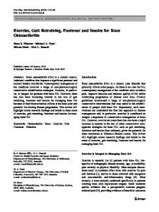
2. Materials and Methods 2.1. Footwear, Tactile sensor and Video recording Commercially available consumer footwear was used in our gait analysis (Figure 1). The safety shoes incorporated a protective steel cap and a hard sole to avoid physical injury. A tactile sensor (F-Scan; NITTA Corp., Tokyo, Japan) was inserted into the footwear as an insole. The 0.15 mm thick sensor with spatial resolution of 5 mm can measure the distribution of dynamic pressure on the sole at a frequency of 100 Hz. The data were converted into displacement of the centroid and its moving velocity on the sole. An ordinary video camera was installed at floor level to monitor foot motion.
Fig. 1. Footwear equipped with tactile sensors 2.2. Equilateral-triangular force plate Figure 2(a) shows a schematic representation of the force plate in plan view, while Figure 2(b) shows the installation of the force plates for gait analysis. The platform had the shape of an equilateral triangle, 1160 mm on each side, as determined from preliminary tests in which six normal subjects trod on pressure-sensitive sheets (Pre-Scale; FUJIFILM, Tokyo, Japan) that were large enough to measure one foot-contact for each leg. The positions of the resultant footprints on the sheets were then measured. The installation of two or more force plates provided a linearly expandable walkway and ensured the capture of a complete stride. This design appeared successful for subjects who walked with pigeon-toed gait (toes turned inward). The walkway plate was composed of two layers, having a total thickness of 30 mm. The top layer was 15 mm thick and was made of vinyl chloride resin, which was convenient for adding or removing the flooring material used in the tests. The bottom layer was 15 mm thick and made of steel, which ensured the requisite minimum flexural rigidity. The two
229
Journal of Biomechanical Science and Engineering
Vol. 2, No. 4, 2007
(a)
(b)
(mx, my)
(0,0)
F-y
Fig. 2(a). Schematic representation of the force plate in plane view. (b). Installation of force plates. The triangular plate paved with carpet is supported at its vertices by transducers. layers were bonded together using an elastic adhesive. This weight-saving structure minimized the effects of plate inertia on the measurement accuracy of the system, and was light enough to be handled by three people during installation. Each triangular plate was supported at its three vertices by transducers. The configuration of these transducers is shown in Figure 3. Each transducer (A, B, and C) was set up by three commercial load cells (a1-a3, b1-b3, or c1-c3) mounted via a 200-mm-wide square plate in an orthogonal system, with a total height of 240 mm. This triaxial transducer had a measuring range of 1960 N vertically and 980 N horizontally, and an overload range of 150%. Linearity was 0.15% of the full-scale maximum and hysteresis was 0.15% of the full-scale maximum. The nine channels of data from the three triaxial transducers were acquired by digital amplifiers with a sampling rate of 400 Hz. All of the amplifiers were synchronized together. The vertical ground reaction force (F-z in Figure 2(a)) was calculated from the sum of the three vertical force components (a1+b1+c1 in Figure 3). Resultant forces in the horizontal plane (anterior–posterior ground reaction force (F-x) and medio–lateral ground reaction force (F-y) in Figure 2(a)) were determined using six horizontal force components (a2, a3, b2, b3, c2, and c3 in Figure 3). Plantar friction (F-f) was defined as the ratio of the resultant force in the horizontal plane to the vertical reaction force: F-f = (F-x2+F-y2)0.5/F-z. To assess the accuracy of measurements of static force, careful measurements undertaken using a discrete known load of up to 784 N were made at every intersection of two sets of lines on the triangular plate (562 points in Figure 3(b)): one set was parallel to the coordinate F-x (see Figure 2) and the other to the coordinate F-y. The distance between two successive lines was 20 mm in both directions. The center of pressure (mx, my) calculated from three vertical force components (a1, b1, c1) was compared with the real position. The assessment showed that the error was less than ±7 mm, except for a few points around the support of the transducers. Applied loads on the walkway plate produced panel-deflection in bending, which led to an insubstantial load on six horizontal load cells (a2, a3, b2, b3, c2, c3) that may in turn have resulted in an error in measuring the horizontal forces. Six sets of quadratic functions (a2-error, a3-error, b2-error, b3-error, c2-error, c3-error) at each assessment point (mx-ref, my-ref) enabled estimations of the insubstantial load for six horizontal load cells (Figure 3(c)):
230
Journal of Biomechanical Science and Engineering
Vol. 2, No. 4, 2007
Fig. 3(a). Transducer mounting points under a triangular walkway plate. (b). Symmetrical grid of 562 points (mx-ref, my-ref) on the walkway plateused in assessing the accuracy of static force measurements. (c). Six sets of quadratic functions (a2-error, a3-error, b2-error, b3-error, c2-error, c3-error) at one assessment point (–220, 200) for estimating insubstantial load for six horizontal load cells .
a2-error(mx-ref, my-ref, F-z) = αa2-mx-my + β a2-mx-my・F-z + γa2-mx-my・F-z2 a3-error(mx-ref, my-ref, F-z) = αa3-mx-my + β a3-mx-my・F-z + γa3-mx-my・F-z2 b2-error(mx-ref, my-ref, F-z) = αb2-mx-my + β b2-mx-my・F-z + γb2-mx-my・F-z2 b3-error(mx-ref, my-ref, F-z) = αb3-mx-my + β b3-mx-my・F-z + γb3-mx-my・F-z2 c2-error(mx-ref, my-ref, F-z) = αc2-mx-my + β c2-mx-my・F-z + γc2-mx-my・F-z2 c3-error(mx-ref, my-ref, F-z) = αc3-mx-my + β c3-mx-my・F-z + γc3-mx-my・F-z2 where α, β and γ are constants for regression curves. Measured values from the six horizontal load cells (a2-m, a3-m, b2-m, b3-m, c2-m, c3-m) were compensated for using a suitable set of functions that were selected by referring to the center of pressure through three vertical load cells: a2= a2-m - a2-error(mx-ref, my-ref, F-z) a3= a3-m - a3-error(mx-ref, my-ref, F-z) b2= b2-m - b2-error(mx-ref, my-ref, F-z) b3= b3-m -b3-error(mx-ref, my-ref, F-z) c2= c2-m - c2-error(mx-ref, my-ref, F-z) c3= c3-m - c3-error(mx-ref, my-ref, F-z)
231
Journal of Biomechanical Science and Engineering
Vol. 2, No. 4, 2007
The natural frequency of vibration of the platform should not overlap any significant frequency components in the ground reaction force of a foot contact because the resulting resonance may obscure the forces being measured. The frequency of vibration was investigated using a fast Fourier transform (FFT). Vertical vibration was not apparent; however, vibration was detected in the horizontal directions (anterior–posterior and medio–lateral) except at the heel contact phase, where frequency was determined as approximately 13 Hz. These two data were filtered by a low-pass filter with a cut-off frequency of 10 Hz. A suite of software written in Microsoft C under MS-DOS was used to continuously correct the force values (F-x, F-y, F-z, mx, my) and plantar friction (F-f), and present these walkway data as a function of time. 2.3. Gait analysis The equilateral-triangular force plates were installed to prepare for the measurement of gait during linear and level walking, as shown in Figure 2(b). Three walkway plates of the same configuration and size, although without transducers, were also installed. Auxiliary plates installed at either end of the triangular walkway plate enabled the subjects to reach their respective steady walking states before entering the triangular walkway panel. We used a flooring material (“Punch-Carpet” in Japanese) that is used extensively in accommodation units, exhibition halls, hotels, schools, medical centers, and other buildings. We studied three normal males, ranging in age from 24 to 33 years. The free gait at the third step was analyzed, with the subject wearing footwear. Subjects were required to begin from a natural standing position on both feet, to start walking from one end of the auxiliary plate, and then walk freely at normal walking speed; they were asked to try not to be self-conscious.
3. Results and Discussion Foot motion and gait classification is shown in Figure 4. Measurements were analyzed from the subject’s third step in the present study; a previous study(1) reported that the subject’s response to a change in their walking environment becomes clear at the third step, where transient walking is regarded to end. Several researchers classify foot motion into three motions: heel contact, flat foot, and toe off. Because human beings walk on two legs, the double-stance phase that includes heel contact and toe off, and the single stance phase with the foot flat, are both found during a single step.
Fig. 4. Classification of gait using video footage (1: heel contact, 3: foot flat, 5: toe off). Figure 5 shows the time history of the magnitude of the vertical ground reaction force (F-z). These representative graphs are derived from the data obtained from the three subjects. The vertical ground reaction force has two peaks, as confirmed previously by
232
Journal of Biomechanical Science and Engineering
Vol. 2, No. 4, 2007
several researchers; the magnitude of the vertical force has a peak that exceeds the body weight in the double stance phase (at heel contact and toe off) and shows a valley in the single support phase. These results confirm that none of the footwear types interrupted normal walking; however, the influence of the footwear on gait pattern was not clear.
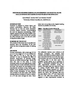
Fig. 5. Time history of the magnitude of the vertical ground reaction force (F-z). Figure 6 shows the time history of plantar friction (F-f). This figure shows similar peaks to those for vertical force (F-z in Figure 5), although with notable variation in the magnitudes of paired peaks. This finding may closely correlate with plantar motion on the floor surface (Figures 4, 7). Friction is produced by a sliding contact between two bearing surfaces(6). Rolling contact also results in friction, but this is considered to be much less than that generated by sliding contact. Sliding contact between the carpet and the sole of the shoe is probably used to the walker’s advantage at heel contact and toe off to aid balance and push the body forward. A single stance phase that includes the foot flat, between heel contact and toe off, plays a role in transferring the centroid on the sole. More friction was produced by rolling contact than sliding, and extremely low friction was recorded in this phase. It was observed that the second peak for canvas shoes was higher than that for any other footwear. The foot can be in a state of dorsal flexion along a line connecting the heads of the first and fifth metatarsals. The flexible sole of canvas shoes may explain this increase in the second peak. For both the first and second peaks, slippers recorded the lowest friction of any footwear; a compensatory action appeared to occur in the gait to prevent the slippers from falling off the foot.
Fig. 6. Time history of plantar friction (F-f).
233
Journal of Biomechanical Science and Engineering
Vol. 2, No. 4, 2007
Fig. 7. Sliding / rolling motion relative to the flooring material and the sole Figure 8 shows the time history of the magnitude of the anterior–posterior ground reaction force (F-x). A posterior F-x force was recorded at heel contact for canvas shoes, safety shoes, and gumboots, but not for slippers. The foot was structurally fixed in all footwear except for slippers, either by a bungee cord, a shoelace, or a bootleg that covered the ankle joint; it is possible that this firm fixation between the footwear and the foot provided a sense of security, as the heel made contact with the ground before the end of extension in the hip joint, as seen in troops on the march.
Fig. 8. Time history of the magnitude of the anterior–posterior ground reaction force (F-x).
Figures 9 and 10 show the displacement of the centroid on the sole and its moving velocity, respectively. The trajectory of the centroid changed with footwear. The moving velocity of the centroid had three peaks per step, synchronous with foot motion. The peaks were observed at heel contact, foot flat, and toe off; however, the peak at foot flat was not clear for the gumboots. The fact that the gumboot covered the ankle joint meant that the mobility of the joint was reduced; consequently, dynamic change was not observed at foot flat. Although the peaks at toe off for the slippers and safety shoes were low, these mechanisms are thought to be different. When wearing slippers, the higher posterior force required to push the body forward at toe off may loosen the slippers from the foot; therefore, the subjects adjusted their mode of locomotion. The safety shoes have protective features such as a hard toe and sole that prevent dorsal flexion along a line connecting the heads of the first and fifth metatarsals; this explained the decrease in peak level at toe off
234
Journal of Biomechanical Science and Engineering
Vol. 2, No. 4, 2007
for these shoes.
Fig. 9. Time history of displacement of the centroid on the sole.
Fig. 10. Time history of moving velocity of the centroid on the sole.
4. Conclusion Change in gait according to footwear was investigated using a tactile sensor and a force plate. The time history of plantar friction, which is proposed as a new evaluation index using a force plate, provides easy-to-understand information regarding the influence of footwear on gait pattern. The evaluation index reveals sliding/rolling motion between the flooring material and the sole. Evaluation of the horizontal ground reaction force at heel contact enabled us to determine the influence on gait of fixation between footwear and the human heel. A tactile sensor was used in determining the moving velocity of the centroid on the sole to evaluate the influences on gait of kinematic constraint of the ankle joint or dorsal flexion at a line connecting the heads of the first and fifth metatarsals.
Acknowledgments This work was supported by the Organization for Creation of New Markets, Oita Prefecture, Japan; the Japan Institute of Construction Engineering, Japan; and the TOSTEM Foundation for Construction Materials Industry Promotion, Japan.
References (1)
Yamashita, T. and Katoh, R.M., Moving Pattern of Point of Application of Vertical Resultant Force During Level Walking, J. Biomechanics, Vol.9, (1976), p.93-99.
235
Journal of Biomechanical Science and Engineering
Vol. 2, No. 4, 2007
(2) (3) (4)
(5) (6)
Nakanishi, Y., Higaki, H., Plantar friction in gait in Japanese houses, Proc. 25th Japanese Biotribology Symposium,(2005), p.97-100. Ito, F., Analysis of Human Motion in Rehabilitation by Micro-computer, Nagoya J. Med. Sci., Vol.46, (1984), p.55-56. Hymd, D., Hughes, S.C. and Ewins, D.J., The Development of a Long, Dual-platform Triaxial Walkway for the Measurement of Forces and Temporal-spatial Data in the Clinical Assessment of Gait, Proc. Instn. Mech. Engrs., Vol.214, Part H, (2000), p.193-201. Morita, S., Analysis of the Fore-aft and Lateral Components of Floor Reaction Force in Normal Gait, Nippon Seikeigeka Gakkai Zasshi, Vol.62, Part H, (1988), p.1221-1232. Bowden, F.P. and Tabor, D., The Friction and Lubrication of Solids I, Oxford, (1954).
236