Triebel, The 80386, 80486 and Pentium Processor. Prof. Yan Luo, UMass Lowell.
1. Chapter 2. Software Architecture of the. 80386 Microprocessor ...
Chapter 2 Software Architecture of the 80386 Microprocessor
Triebel, The 80386, 80486 and Pentium Processor Prof. Yan Luo, UMass Lowell
1
Outline 2.2 Internal Architecture of the 80386 Microprocessor 2.3 Software Model of the 80386 Microprocessor 2.4 Memory Address Space and Data Organization 2.5 Data Types 2.6 Segment Registers and Memory Segmentation 2.7 Instruction Pointer 2.8 Data Registers 2.9 Pointer and Index Registers 2.10 Flags Register 2.11 Generating a Memory Address 2.12 The Stack 2.13 Input/Output Address Space Triebel, The 80386, 80486 and Pentium Processor Prof. Yan Luo, UMass Lowell
2
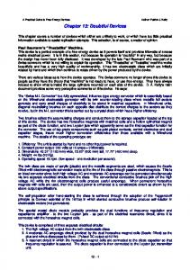
Internal Architecture of the 80386DX Microprocessor
parallel processing -> high performance Six processing units: • Bus units • Execution unit • Segment unit • Page unit • Prefetch unit • Decode unit Each unit has a dedicated function and they all operate at the same time
Triebel, The 80386, 80486 and Pentium Processor Prof. Yan Luo, UMass Lowell
3
Bus Interface Unit
Interface to the outside world Responsible for
• • •
Fetching instruction Reading and writing of data for memory Inputting and outputting of data for input/output peripherals
Information transfers over the microprocessor bus
• •
De-multiplexed bus 386DX • 32-bit data bus • Real-mode: 20-bit address, 1M-byte physical address space • Protected-mode: 32-bit address bus, 4G-byte physical address space Triebel, The 80386, 80486 and Pentium Processor Prof. Yan Luo, UMass Lowell
4
Prefetch Unit
Instruction Stream queue Whenever the queue is not full, prefetch the next sequential instructions
• •
Queue—16-byte; 4-byte/memory cycle Prioritizes bus accesses—data operands highest priority
FIFO instruction queue Holds bytes of instruction code until the decode unit is ready to accept them. Time to fetch many of the instructions in a microcomputer program is “hidden”. Bus unit “Idle state” - If queue is full and the execution unit is not requesting access to data in memory, BIU does not perform bus cycles. Triebel, The 80386, 80486 and Pentium Processor Prof. Yan Luo, UMass Lowell
5
Decode Unit
Offloads the responsibility of instruction decoding from the execution unit. Reads machine code instructions from the output side of the instruction queue Decodes the instructions into the microcode instruction format used by the execution unit Contains an instruction queue that holds 3 fully decoded instruction Decoded instructions are held until requested by the execution unit Triebel, The 80386, 80486 and Pentium Processor Prof. Yan Luo, UMass Lowell
6
Execution Unit
Responsible for executing instructions Element of the EU • Arithmetic/logic unit (ALU)
•
• • • •
Performs the operation identified by the instruction: ADD, SUB, AND, etc.
Flags register
•
Holds status and control information
General-purpose registers
•
Holds address or data information
Control ROM
•
Contains microcode sequences that define operations performed by machine instructions
Special multiply, shift, and barrel shift hardware
•
Accelerate multiply, divide, and rotate operations Triebel, The 80386, 80486 and Pentium Processor Prof. Yan Luo, UMass Lowell
7
Operations of the Execution Unit
Reads instructions from the instruction queue Accesses general purpose registers if necessary Generates memory address of data storage locations in memory if necessary Passes memory addresses to the segmentation and paging units and requests the bus unit to perform read or write bus cycles to access data operands in memory Performs the operation defined by the instruction on the selected data Tests the state of flags if necessary Updates the state of the flags based on the result produced by executing the instruction. Triebel, The 80386, 80486 and Pentium Processor Prof. Yan Luo, UMass Lowell
8
Segmentation and Paging Unit
Off-load memory-management and protection services from the bus unit Segmentation unit • Implements real-mode and protected-mode segmentation model • Contains general registers, segment registers, and instruction pointer • Holds address and data operand information Segmentation unit address generation logic • Real-mode address generation
• •
• •
CS:IP → code DS:SI → data
Protected-mode address translation
•
Translates logical address to linear address
Protection checking Triebel, The 80386, 80486 and Pentium Processor Prof. Yan Luo, UMass Lowell
9
Segmentation and Paging Unit
Paging unit • Implements protected-mode paging model • Contains translation look-aside buffer • Acts as a cache for recently used page directory entries and page table entries • Translates linear address output of segmentation unit to a physical page address • Not used in real mode
Triebel, The 80386, 80486 and Pentium Processor Prof. Yan Luo, UMass Lowell
10
The Software Model
programmer’s understanding the operation of the microcomputer from a software point of view Elements of the software model
• • •
Register set Memory address space Input/output address space
What the programmer must know about the microprocessor
• • • • • • • •
Registers available within the device Purpose of each registers Function of each registers Operating capabilities of each registers Limitations of each register Size of memory and input/output address spaces Organization of memory and input/output address spaces Types of data Triebel, The 80386, 80486 and Pentium Processor Prof. Yan Luo, UMass Lowell
11
Register Set
8- 32-bit registers
• • •
(4) Data registers- EAX, EBX, ECX, EDX, can be used as 32, 16 or 8bit (2) Pointer registers- EBP, ESP (2) Index registers- ESI, EDI
7- 16-bit registers
• •
(1) Instruction pointer- IP (6) Segment registers- CS, DS, SS, ES, FS, GS
Flags (status) register-EFLAGS Control register- CR0
Triebel, The 80386, 80486 and Pentium Processor Prof. Yan Luo, UMass Lowell
12
Memory and Input/Output
Architecture implements independent memory and input/output address spaces Memory address space- 1,048,576 bytes long (1M-byte) Input/output address space- 65,536 bytes long (64K-bytes)
Triebel, The 80386, 80486 and Pentium Processor Prof. Yan Luo, UMass Lowell
13
Address Space
Memory organized as individual bytes Memory address space corresponds to the 1M addresses in the range 00000H to FFFFFH 00000H= 000000000000000000002 FFFFFH= 111111111111111111112 220= 1,048,576 = 1M unique addresses Data organization: • Byte: content of any individual byte address • Word: contents of two contiguous byte addresses • Double-word: contents of 4 contiguous byte addresses
Triebel, The 80386, 80486 and Pentium Processor Prof. Yan Luo, UMass Lowell
14
Dedicated and General Use of Memory
Memory address space is partitioned into general use and dedicated use areas Dedicated (0H – 3FFH): • Interrupt vector table • 1st 1024 bytes
•
•
Addresses 0H → 3FFH
256 4-byte pointers
• •
16-bit segment base address 16-bit offset
General use: • 400H → FFFFFH • Used for stack, code, and data
Triebel, The 80386, 80486 and Pentium Processor Prof. Yan Luo, UMass Lowell
15
Aligned Words, Double words • Words and double words of data can
be stored in memory at an even or odd address boundary
• •
•
Examples of even address boundaries: 0000016, 0000216, 0000416 Examples of odd address boundaries: 0000116, 0000316, 0000516
Aligned double-words are stored at even addresses that are a multiple of 4
•
Examples are double words 0 and 4
Triebel, The 80386, 80486 and Pentium Processor Prof. Yan Luo, UMass Lowell
16
Misaligned Words
80x86 architecture supports access or aligned or misaligned data Words stored across a double-word boundary are said to be “misaligned or unaligned words ” Examples are words 3 and 7 Misaligned double-words are stored at addresses that are not a multiple of 4 Examples: double words 1, 2 and 3 There is a performance impact for accessing unaligned data in memory (32-bit data bus)
Triebel, The 80386, 80486 and Pentium Processor Prof. Yan Luo, UMass Lowell
17
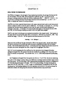
Examples of Words of Data “little endian” organization
Most significant byte at high address Least significant byte at low address
Example [Fig. 2.5 (a)] (0200116) = 0101 10102=5AH= MS-byte (0200016) = 1111 00002=F0H= LS-byte as a word they give 01011010 111100002=5AF0H
Triebel, The 80386, 80486 and Pentium Processor Prof. Yan Luo, UMass Lowell
18
Example of Double Word
LSB: Address 02102H = CDH MSB: Address 02105H = 01H Arranging as 32-bit data gives Address 02102H =0123ABCDH = 00000001 00100011 10101011 110011012
Aligned or misaligned double word?
Triebel, The 80386, 80486 and Pentium Processor Prof. Yan Luo, UMass Lowell
19
Unsigned Integers
All numbers are binary in memory All bits represent data Types: Sizes Range 8-bit 0H → 25510 16-bit 0H → 65,53510 32-bit 0H → 4,294,967,29510
Triebel, The 80386, 80486 and Pentium Processor Prof. Yan Luo, UMass Lowell
20
Signed Integers
MSB is sign bit ( 0/1 -> +/-) Remaining bits represent value Negative numbers expressed in 2’s complement notation Types: Sizes Range 8-bit -128 → +127 16-bit -32,768 → +32,767 32-bit -2,147,483,648 → +2,147,483,647 Triebel, The 80386, 80486 and Pentium Processor Prof. Yan Luo, UMass Lowell
21
Integer Examples Example 2.3 Unsigned double word integer = 00010000H Expressing in binary form = 0000 0000 0000 0001 0000 0000 0000 00002 = 216 = 65,536 Example 2.4 Signed double word integer = FFFEFFFFH Expressing in binary form = 1 111 1111 1111 1110 1111 1111 1111 11112 Sign bit = 1 = minus Subtracting 1 from LSB and complementing all bits gives = - 000 0000 0000 0001 0000 0000 0000 00012 = - 216 + 20 = - 65,537 Triebel, The 80386, 80486 and Pentium Processor Prof. Yan Luo, UMass Lowell
22
BCD Numbers Direct coding of numbers as binary coded decimal (BCD) numbers supported Unpacked BCD [Fig.2.10(b)] • Lower four bits contain a digit of a BCD number • Upper four bits filled with zeros (zero filled) Packed BCD [Fig. 2.10(c)] • Lower significant BCD digit held in lower 4 bits of byte • More significant BCD digit held in upper 4 bits of byte Example: Packed BCD byte at address 01000H is 100100012, what is the decimal number? Organizing as BCD digits gives, 1001BCD 0001BCD = 9110
Triebel, The 80386, 80486 and Pentium Processor Prof. Yan Luo, UMass Lowell
23
ASCII Data American Code for Information Interchange (ASCII) code ASCII information storage in memory • Coded one character per byte • 7 LS-bits = b7b6b5b4b3b2b1 • MS-bit filled with 0 Example: Addresses 01100H-01104H contain ASCII coded data 01000001, 01010011, 01000011, 01001001, and 01001001, respectively. What does the data stand for? 0 100 0001ASCII = A 0 101 0011ASCI = S 0 100 0011ASCII = C 0 100 1001ASCII = I 0 100 1001ASCII = I
Triebel, The 80386, 80486 and Pentium Processor Prof. Yan Luo, UMass Lowell
24
Active Segments of Memory Memory Segmentation Not all of the 80386 real-mode address space is active at one time Address value in a segment register points to the lowest addressed byte in an active segment Size of each segment is 64K contiguous byte Total active memory is 384k bytes 64K-bytes for code 64K-bytes for stack 256K-bytes for data Six Segment Registers Code segment (CS) register- Code storage Stack segment (SS) register- Stack storage Data segment (DS, ES, FS, GS) registerData storage
Triebel, The 80386, 80486 and Pentium Processor Prof. Yan Luo, UMass Lowell
25
User access, Restrictions, and Orientation Segment registers are user accessible Programmer can change values under software control Permits access to other parts of memory Example: a new data space can be activated by replace values in DS, ES, FS, and GS Restriction on the starting address of a segment of memory Reside on a 16 byte address boundary Examples: 00000H, 00010H, 00020H Orientation of segments: Contiguous—A&B or D,E&G Adjacent—none shown Disjointed—C&F Overlapping—B&C
Triebel, The 80386, 80486 and Pentium Processor Prof. Yan Luo, UMass Lowell
26
Accessing Code Memory Space Instruction pointer (IP): location of the next double word of instruction code to be fetched from the current code segment 16-bit offset—address pointer Logical address CS:IP forms 20-bit physical address for next instruction Instruction fetch sequence 80386DX prefetches a double word of instruction code from code segment in memory into instruction stream queue IP = IP + 4 Decoded by the instruction decoder Placed in the instruction queue to await execution 80386DX prefetches up to 16 byte of code Decoded instruction is read from output of instruction queue Operands read from data memory, internal registers, or the instruction queue Operation specified by the instruction performed on operands Results written to data memory or and internal register Flags updated
Triebel, The 80386, 80486 and Pentium Processor Prof. Yan Luo, UMass Lowell
27
General Purpose Data Registers
Four general purpose data registers Accumulator (A) register Base (B) register Count (C) register Data (D) register
Can hold 8-bit, 16-bit, or 32-bit data AH/AL = high and low byte value AX = word value EAX = double word value
Uses: Hold data such as source or destination operands for most operations—ADD, AND, SHL Hold address pointers for accessing memory
Some also have dedicated special uses C—count for loop, B—table look-up translations, base address D—indirect I/O and string I/O
Triebel, The 80386, 80486 and Pentium Processor Prof. Yan Luo, UMass Lowell
28
Pointer Registers Pointers are offset addresses used to access information in a segment of memory Two pointer registers Stack pointer register ESP = 32-bit extended stack pointer SP = 16-bit stack pointer Base pointer register EBP = 32-bit extended base pointer BP = 16-bit base pointer Use to access information in stack segment of memory SP and BP are offsets from the current value of the stack segment base address Select a specific storage location in the current 64K-byte stack segment SS:SP—points to top of stack (TOS) SS:BP—points to data in stack
Triebel, The 80386, 80486 and Pentium Processor Prof. Yan Luo, UMass Lowell
29
Index Registers Value in an index register is also an address pointer Two index registers Source index register
ESI = 32-bit source index register SI = 16-bit source index register
Destination index registers EDI = 32-bit destination index register DI = 16-bit destination index register
Used to access source and destination operands in data segment of memory
DS:SI—points to source operand in data segment DS:DI—points to destination operand in data segment Also used to access information in the extra segment (ES)
Triebel, The 80386, 80486 and Pentium Processor Prof. Yan Luo, UMass Lowell
30
Flags Register FLAGS register: 32-bit register used to hold single bit status and control information called flags 9 active flags in real mode Two categories Status Flags—indicate conditions that are the result of executing an instruction Execution of most instructions updates status Used by control flow instructions as test conditions Control Flags—control operating functions of the processor Used by software to turn on/off operating capabilities
Triebel, The 80386, 80486 and Pentium Processor Prof. Yan Luo, UMass Lowell
31
Status Flags
Examples of Status Flags—CF, PF, ZF, SF, OF, AF Carry flag (CF) 1 = carry-out or borrow-in from MSB of the result during the execution of an arithmetic instruction 0 = no carry or borrow has occurred Parity flag (PF) 1 = result produced has even parity 0 = result produced has odd parity Zero flag (ZF) 1 = result produced is zero 0 = result produced is not zero Sign bit (SF) 1 = result is negative 0 = result is positive Others Overflow flag (OF) Auxiliary carry flag (AF)
Triebel, The 80386, 80486 and Pentium Processor Prof. Yan Luo, UMass Lowell
32
Control Flags Trap flag (TF) 1/0 = turn on/off single-step mode Mode useful for debugging Employed by monitor to execute one instruction at a time (single step execution)
Interrupt flag (IF) Used to enable/disable external maskable interrupt requests 1/0 = enable/disable external interrupts
Direction flag (DF) Used to determine the direction in which string operations occur 1/0 = automatically decrement/increment string address—proceed from high address to low address
Triebel, The 80386, 80486 and Pentium Processor Prof. Yan Luo, UMass Lowell
33
Logical and Physical Addresses Logical address: real-mode architecture described by a segment base address and an offset
Segment base address (CS,DS, ES, SS, etc.) are 16 bit quantities Offsets (IP, SI, DI, BX, DX, SP, BP, etc.) are 16bit Examples: CS:IP 100H:100H Code access DS:SI 2000H:1EFH Data access SS:SP F000H:FFH Stack access
Physical Address: actual address used for accessing memory
20-bits in length Formed by: Shifting the value of the 16-bit segment base address left 4 bit positions Filling the vacated four LSBs with 0s Adding the 16-bit offset
Triebel, The 80386, 80486 and Pentium Processor Prof. Yan Luo, UMass Lowell
34
Generating a Real-Mode Memory Address Segment base address = 1234H Offset = 0022H 1234H = 00010010001101002 0022H = 00000000001000102 Shifting base address, 000100100011010000002 = 12340H Adding binary segment address and offset 000100100011010000002 + 00000000001000102 = 000100100011011000102 = 12362H In hex: 12340H + 0022H = 12362H Triebel, The 80386, 80486 and Pentium Processor Prof. Yan Luo, UMass Lowell
35
Boundaries of a Segment Six active segments: CS, DS, ES. GS, FS, SS Each 64K-bytes in size maximum of 384K-bytes of active memory 64K-bytes for code 64K-bytes for stack 256K-bytes for data Starting address of a data segment DS:0H lowest addressed byte Ending address of a data segment DS:FFFFH highest addressed byte Address of an element of data in a data segment DS:BX address of a byte, word, or double word element of data in the data segment
Triebel, The 80386, 80486 and Pentium Processor Prof. Yan Luo, UMass Lowell
36
Relationship between Logical and Physical Addresses
Many different logical address can map to the same physical address
Examples:
2BH:13H = 002B0H+0013H = 002C3H 2CH:3H = 002C0H + 0003H = 002C3H
Said to be “aliases”
Triebel, The 80386, 80486 and Pentium Processor Prof. Yan Luo, UMass Lowell
37
The Stack Stack—temporary storage area for information such as data and addresses Located in stack segment of memory Real mode—64K bytes long Organized as 32K words Information saved as words or double words, not bytes Organization of stack SS:0002H end of stack (lowest addressed word) SS:FFFEH bottom of stack (highest addressed word) SS:SP top of stack (last stack location where data was pushed) Stack grows down from higher to lower address Used by call, push, pop, and return operations PUSH ESI causes the current content of the ESI register to be pushed onto the stack POP ESI causes the value at the top of the stack to be popped back into the ESI register
Triebel, The 80386, 80486 and Pentium Processor Prof. Yan Luo, UMass Lowell
38
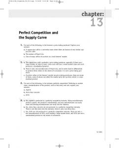
The Stack - Push Stack Operation Status of the stack prior to execution of the instruction PUSH AX
AX = 1234H SS = 0105H AEOS = SS:02 01052H = end of stack SP = 0008H ATOS = SS:SP 01058H = current top of stack ABOS = SS:FFFE 1104EH BBAAH = Last value pushed to stack Addresses < 01058H = invalid stack data Addresses >= 01058H = valid stack data
In response to the execution of PUSH AX instruction
1. SP 0006 decremented by 2 ATOP 01056H 2. Memory write to stack segment AL = 34H 01056H AH = 12H 01057H Triebel, The 80386, 80486 and Pentium Processor Prof. Yan Luo, UMass Lowell
39
The Stack- Pop Stack Operation Status of the stack prior to execution of the instruction POP AX AX = XXXXH SS = 0105H SP = 0006H ATOS = SS:SP 01056H = current top of stack 1234H = Last value pushed to stack Addresses < 01056H = invalid stack data Addresses >= 01056H = valid stack data
1
2
execution of POP AX instruction 1. Memory read to AX 01056H = 34H AL 01057H = 12H AH 2. SP 0008H incremented by 2 ATOP 01058H
execution of POP BX instruction 1. Memory read to BX 01058H = AAH BL 01059H = BBH BH 2. SP 000AH incremented by 2 ATOP 0105AH
Triebel, The 80386, 80486 and Pentium Processor Prof. Yan Luo, UMass Lowell
40
I/O Address Space Input/output address space Place where I/O devices are normally implemented I/O addresses are only 16-bits in length Independent 64K-byte address space Address range 0000H through FFFFH Page 0 First 256 byte addresses 0000H - 00FFH Can be accessed with direct or variable I/O instructions Ports F8H through FF reserved
Triebel, The 80386, 80486 and Pentium Processor Prof. Yan Luo, UMass Lowell
41
Organization of the I/O Data Input/output data organization Supports byte, word, and double-word I/O ports 64K independent byte-wide I/O ports 32K independent word-wide I/O ports 16K independent double-word-wide I/O ports Examples (aligned I/O ports): Byte ports 0,1,2 addresses 0000H, 0001H, and 0002H Word ports 0,1,2 addresses 0000H, 0002H, 0004H Double-word ports 0,1,2 addresses 0000H, 0004H, 0008H Advantages of Isolated I/O Complete memory address space available for use by memory I/O instructions tailored to maximize performance Disadvantage of Isolated I/O All inputs/outputs must take place between I/O port and accumulator register
Triebel, The 80386, 80486 and Pentium Processor Prof. Yan Luo, UMass Lowell
42