applied sciences Article
Characterization of Transition-Metal Oxide Deposition on Carbon Electrodes of a Supercapacitor Ying-Chung Chen 1 , Chih-Yu Wen 1 , Chih-Ming Wang 2, *, Chia-Wei Ho 1 , Shih-Yuan Lin 1 and Ying-Lin Chen 1 1
2
*
Department of Electrical Engineering, National Sun Yat-Sen University, Kaohsiung 804, Taiwan;
[email protected] (Y.-C.C.);
[email protected] (C.-Y.W.);
[email protected] (C.-W.H.);
[email protected] (S.-Y.L.);
[email protected] (Y.-L.C.) Department of Electrical Engineering, Cheng Shiu University, Kaohsiung 833, Taiwan Correspondence:
[email protected]; Tel.: +886-7-7310606; Fax: +886-7-7337390
Academic Editor: Jiazhao Wang Received: 30 September 2016; Accepted: 5 December 2016; Published: 7 December 2016
Abstract: In order to fabricate the composite electrodes of a supercapacitor, transition-metal oxide materials NiO and WO3 were deposited on carbon electrodes by electron beam evaporation. The influences of various transition-metal oxides, scan rates of cyclic voltammograms (CVs), and galvanostatic charge/discharge tests on the characteristics of supercapacitor were studied. The charge/discharge efficiency and the lifetime of the composite electrodes were also investigated. It was found that the composite electrodes exhibited more favorable capacitance properties than those of the carbon electrodes at high scan rates. The results revealed the promotion of the capacitance property of the supercapacitor with composite electrode and the improving of the decay property in capacitance at high scan rate. In addition, the charge/discharge efficiency is close to 100% after 5000 cycles, and the composite electrode retains strong adhesion between the electrode material and the substrate. Keywords: electron beam evaporation; composite electrode; supercapacitor; charge/discharge efficiency
1. Introduction A supercapacitor is a new storage device positioned between traditional capacitors and batteries. Electrochemically activated materials or porous materials are used for storage in a supercapacitor. The advantages of a supercapacitor are its high power density, high energy density, excellent cycle life, and fast charge and discharge times [1,2]. Supercapacitors have attracted considerable attention in recent years because they do not have the disadvantages that traditional batteries and capacitors have. It has been discovered that charges can be separated using Coulomb electrostatic force and form double layers across the surface of electrodes and electrolytes [3]. The concept of an electrical double-layer capacitor (EDLC) involves applying DC voltage to electrodes, which are typically porous carbon, to establish an electrical double-layer for charges storage. A pseudocapacitor stores electrical energy through rapid and continuous redox reactions between the electrodes and the electrolyte. Metal oxides and conducting polymers are commonly used as the electrode materials in pseudocapacitors. Porous carbon is usually chosen as the electrode material in commercial products because of the high cost of metal oxides and the poor stability of the conducting polymers. Therefore, composite electrodes exhibit such advantages as double-layer capacitance and pseudo-capacitance [4,5].
Appl. Sci. 2016, 6, 413; doi:10.3390/app6120413
www.mdpi.com/journal/applsci
Appl. Sci. 2016, 6, 413
2 of 8
Beliakov et al. prepared an asymmetrical composite electrode by using NiO and carbon in 1999, and the results showed more favorable energy density than carbon–carbon electrodes [6]. However, Takasu et al. in 1999 proposed a oxide composite consisting of Ti, V, and W oxides for the application of ECs [7]; meanwhile Jeong and Manthiram reported that RuO2 coated with WO3 showed good capacitive performances in both acidic and alkaline media in 2001 [8,9]. In 2005, Yuan et al. showed a hybrid-type electrochemical capacitor, in which the activated-carbon (AC) load with nickel oxide was used as cathode material and the activated-carbon was used as anode material. Although the BET surface area of the activated-carbon decreased after nickel oxide loading compared with that of the starting material, its specific capacitance increased 10.84%, from 175.40 to 194.01 F·g−1 [10,11]. Recently, amorphous tungsten oxide with microwave radiation was reported to be a promising electrode material for electrochemical capacitors (ECs) [12]. Accordingly, tungsten oxides and NiO of certain microstructures should be of pseudocapacitive behavior. In this study, the carbon electrode using mesocarbon microbeads (MCMBs) was adopted for the fabrication of a supercapacitor. To fabricate the composite electrodes of the supercapacitor, NiO and WO3 layers were deposited onto carbon electrodes using electron beam evaporation. This technique, one of the physical vapor deposition methods, was chosen largely for the growth of device quality films [13]. The influences of various scan rates of the cyclic voltammograms (CVs) on the characteristics of capacitance were studied. The charge/discharge efficiency and lifetime of the composite electrodes were also discussed. 2. Experimental 2.1. Preparation of Carbon Electrodes Conductivity percolation was found to play a critical role in determining the electrochemical capacitive behavior of the carbon–carbon composite electrode, which is comprised of a non-conductive activated carbon with a large surface area and a conductive carbon black (CB) with a small surface area [14]. Therefore, CB powder (10 wt %) was added to 1 g of MCMB powder and mixed uniformly. The mixing powder was added to a solution containing 2 wt % polyvinyl butyral (PVB) and 9.1 mg of dimethylacetamide (DMA). The mixture was mixed at room temperature (R.T.) to form a carbon slurry. The electrodes were prepared by spin-coating the carbon slurry onto ITO glass (transmittance of 85%, sheet resistance of 15 Ω·sq−1 .) and then evaporating the solvent, DMA, in an oven at 150 ◦ C for 10 min. 2.2. Fabrication of Composite Electrodes First, WO3 and NiO were, respectively, deposited using an electron beam evaporation technique onto the MCMB/ITO substrates. A high-purity WO3 powder (99.8%, Alfa Aesar, Heysham, UK) and a NiO powder (99%, Sigma-Aldrich, St. Louis, MO, USA) were used as the evaporation materials. The vacuum chamber was initially pumped to a pressure of 5 × 10⁻⁶ Torr before evaporation. A working pressure of approximately 1 × 10⁻⁵ Torr was maintained throughout the evaporating process. The distance between the powder and the substrate was 20 cm. The powders were heated using an electron beam that was collimated from the DC heated cathode of a tungsten filament. The surface of the powders was scanned using a 270◦ deflected electron beam at an accelerating voltage of 4 kV. The thickness of the films and the deposition rate were controlled using the quartz crystal monitor. Prior to evaporation, a pre-evaporating process was performed for 5 min to remove contaminants from the powder. MCMB/ITO glass was used as the substrate. Continuous rotation of the substrates during the deposition process facilitated the formation of homogeneous and uniform films on the substrate surface. The evaporation rate of 0.5 nm·s−1 was adopted to deposit all films. The preparation flow diagram of composite electrodes is shown in Figure 1.
Appl. Sci. Sci. 2016, 2016,6, 6,413 413 Appl.
of 88 33 of
Figure 1. 1. The Thepreparation preparation flow flow diagram diagram of of the the composite composite electrode. electrode. Figure
2.3. 2.3. Characterization Characterization and and Electrochemical Electrochemical Properties Properties The The crystalline crystalline structure structure of of the the films films was was analyzed analyzed using using X-ray X-ray diffraction diffraction (XRD, (XRD, PANalytical PANalytical X’Pert X’Pert PRO, PRO, Almelo, Almelo, Netherlands) Netherlands) with with Cu Cu Kα Kα radiation radiation (λ (λ == 0.1542 0.1542 nm). nm). Step Step scans scans performed performed at at aa ◦ ·min−1 −1were scan scan rate rate of 33°·min wereperformed performedininthe the2θ 2θ ranged ranged from from 10° 10◦ to to 70°. 70◦ . The The thickness thickness and and surface surface microstructures microstructures of of the the films films were were investigated investigated using using aa scanning scanning electron electron microscope microscope (SEM, (SEM, ZEISS, ZEISS, Auriga-39-50, Auriga-39-50, Oberkochen, Oberkochen, Germany). Germany). The The characterization characterization of of the the electrochemical electrochemical properties properties was was conducted conducted in in aa 2-electrode 2-electrode cell cell by by using using an an electrochemical electrochemical analyzer analyzer (CHI, (CHI,6273B, 6273B,Austin, Austin,TX, TX,USA). USA). The curves were wereused usedto toanalyze analyzethe thevoltage voltageand andcurrent current changes, which used M4 Et 4NBF as The CVs curves changes, which used 1 M1 Et NBF 4 as4 an 1 and−1atand an electrolyte scanned at a rate scanofrate of 25 at a voltage of3·3V.VThe to following 3 V. The electrolyte andand scanned at a scan 25 mV ·s−mV·s a voltage range ofrange ·3 V to following equation was used tothe calculate specific capacitance [15]: equation was used to calculate specificthe capacitance [15]: 11 w V2 dQdQ × I (V )dV C =C = dV==44× mv ΔV V V I (V )dV dV mv∆V 1 V2 1
(1) (1)
V
where r V22 I (V )dV is the hysteresis loop area, υ is the scan rate, ΔV is the range of potential, and m is where VV1 I (V )dV is the hysteresis loop area, υ is the scan rate, ∆V is the range of potential, and m is 1 the total total weight weight of of the electrode material. the 3. Results Results and and Discussion Discussion 3. Figure 22shows showsthat thatthe the carbon electrode prepared using the MCMB was an amorphous Figure carbon electrode prepared using the MCMB was in an in amorphous state. ◦ and 43.2◦ of 2θ correspond to the (111) and (200) state. According to the JCPDS cards, peaks at 37.2 According to the JCPDS cards, peaks at 37.2° and 43.2° of 2θ correspond to the (111) and (200) diffractions of of NiO NiO (JCPDS (JCPDS files: files: 20-1324) 20-1324) deposited deposited on on the the carbon carbon electrode. electrode. However, However, there there were were diffractions not obvious obvious diffraction diffraction peaks peaks for for WO WO33 deposited deposited on on the the carbon carbon electrode; electrode; therefore, therefore, itit was was in in an an not amorphous state. Because WO films were deposited at R.T., the amount of energy was insufficient to amorphous state. Because WO33 films were deposited at R.T., the amount of energy was insufficient induce crystalline growth. to induce crystalline growth.
Appl. Sci. 2016, 6, 413 Appl. Sci. 2016, 6, 413 Appl. Sci. 2016, 6, 413
4 of 8 4 of 8 4 of 8
Figure 2. 2. X-ray X-ray patterns of the composite electrodes: (a) ITO/glass substrate; (b) MCMB/ITO/glass; (c) Figure patternsof ofthe thecomposite compositeelectrodes: electrodes:(a) (a)ITO/glass ITO/glass substrate; MCMB/ITO/glass; Figure 2. X-ray patterns substrate; (b)(b) MCMB/ITO/glass; (c) NiO/MCMB/ITO/glass; (d) WO 3/MCMB/ITO/glass. (c) NiO/MCMB/ITO/glass; (d)3/MCMB/ITO/glass. WO3 /MCMB/ITO/glass. NiO/MCMB/ITO/glass; (d) WO
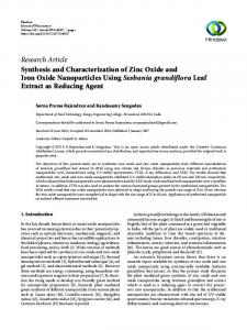
Figure 3 shows the morphologies of a layer NiO deposited on the activated carbon surface. The Figure 33 shows a layer NiO deposited on the activated carbon surface. The showsthe themorphologies morphologiesofof a layer NiO deposited on the activated carbon surface. WO3 films deposited on the activated carbon are round rock structures as shown in Figure 4. Cracks WO films deposited on theon activated carboncarbon are round rock structures as shown Figure Cracks The 3WO deposited the activated are round rock structures as in shown in 4.Figure 4. 3 films are visible on the WO3 films. The MCMB has a high specific surface area and porosity. The thickness are visible the WO The MCMB has a high specific surface area and porosity. The thickness Cracks areon visible on3 films. the WO films. The MCMB has a high specific surface area and porosity. 3 films deposited on the MCMB surface is about 500 nm via electron of the metal oxide (WO3 or NiO) of the metal oxide 3 oroxide NiO)(WO films deposited on deposited the MCMBonsurface is about 500 nm via electron The thickness of the(WO metal NiO) films the MCMB surface is about 500 nm 3 or beam evaporation. This caused cracks, but a high power density of the supercapacitor with beam evaporation. This causedThis cracks, butcracks, a high of the of supercapacitor with via electron beam evaporation. caused butpower a high density power density the supercapacitor composite structure electrodes was obtained. Electrochemical measurements were conducted in a composite structure electrodes waswas obtained. Electrochemical measurements with composite structure electrodes obtained. Electrochemical measurementswere wereconducted conducted in in a 2-electrode disc-type cell (capacitor), in which a separator was soaked in 1 M Et4NBF4 and inserted 2-electrode disc-type cell (capacitor), in which a separator was soaked in in 11 M M Et Et44NBF44 and inserted between the two carbon electrodes. A voltage ranges of −3.0 to 3.0 V was applied. between the two carbon electrodes. A voltage ranges of −3.0 −3.0to to3.0 3.0VVwas wasapplied. applied.
Figure 3. SEM morphologies and EDS of the NiO thin films deposited on the carbon electrode: (a) the Figure 3. SEM morphologies and EDS of the NiO thin films deposited on the carbon electrode: (a) the Figure 3. SEMofmorphologies and EDS of the NiO thin films deposited on the carbon electrode: magnification 1000× (b) the magnification of 30,000×. magnification of 1000× (b) the magnification of 30,000×. (a) the magnification of 1000× (b) the magnification of 30,000×.
Appl. Sci. 2016, 6, 413 Appl. Sci. 2016, 6, 413 Appl. Sci. 2016, 6, 413
5 of 8 5 of 8 5 of 8
3 thin films deposited on the carbon electrode: (a) Figure 4. SEM the WO Figure SEMmorphologies morphologiesand andEDS EDSof the WO films deposited carbon electrode: 3 thin 3 thin films deposited on on thethe carbon electrode: (a) Figure 4. 4. SEM morphologies and EDS ofofthe WO the magnification of 1000× (b) the magnification of 30,000×. (a) the magnification of 1000 × (b) the magnification of 30,000 × . the magnification of 1000× (b) the magnification of 30,000×.
While at lower scan rates all the active surface area can be utilized for charge storage [16]. While at at lower lower scan scan rates rates all all the the active active surface While surface area area can can be be utilized utilized for for charge charge storage storage [16]. [16]. Therefore, a smooth current peak was obtained. However, the current peak increased with the Therefore, a smooth current peak was obtained. However, the current peak increased with the Therefore, a smooth current peak was obtained. However, the current peak increased with the increasing scan rate. As the scan rate of the CVs gradually increased, the shape of the CVs changed increasing scan scan rate. rate. As the scan scan rate rate of of the the CVs CVs gradually gradually increased, increased, the the shape shape of of the the CVs CVs changed changed increasing As the from rectangular to ovular. In Figure 5, when the scan rate was 25–200 mV·s−1−1, carbon electrodes and − 1 from rectangular to ovular. In Figure 5, when the scan rate was 25–200 mV·s , carbon electrodes and from rectangular to ovular. In Figure 5, when the scan rate was 25–200 mV·s , carbon electrodes composite electrodes exhibited a similar hysteresis area of CVs. However, when the scan rate composite electrodes exhibited a similar hysteresis area of CVs. However, when the scan rate and composite electrodes exhibited a similar hysteresis area of CVs. However, when the scan rate exceeded 250 mV·s−1 the hysteresis area of the CVs of the composite electrodes was larger than that −1,1 exceeded 250 250 mV mV·s , ,the than that that exceeded ·s− thehysteresis hysteresisarea areaof ofthe the CVs CVs of of the the composite composite electrodes electrodes was was larger larger than of the carbon electrodes. The composite electrode, on which NiO was deposited, exhibited a larger of the carbon electrodes. The composite electrode, on which NiO was deposited, exhibited a larger of the carbon electrodes. The composite electrode, on which NiO was deposited, exhibited a larger hysteresis area. hysteresis area. area. hysteresis
Figure 5. CVs of the carbon electrodes and the composite electrodes in 1M Et4NBF4 solution at Figure 5.5.CVs carbon electrodes and and the composite electrodes in 1M Et at various CVsofofthethe carbon electrodes the composite electrodes in4 NBF 1M Et 4NBF4 solution at 4 solution various scan rates: (a) 25 mV/s (b) 50 mV/s (c) 100 mV/s (d) 200 mV/s (e) 250 mV/s (f) 500 mV/s. scan rates: (a)rates: 25 mV/s 50 mV/s 100 (c) mV/s 200(d) mV/s (e) 250(e) mV/s (f) 500 various scan (a) 25(b) mV/s (b) 50(c) mV/s 100 (d) mV/s 200 mV/s 250 mV/s (f)mV/s. 500 mV/s.
Table 1 shows the specific capacitances that were calculated using Equation (1) at various scan Table 11 shows shows the the specific specific capacitances capacitances that that were were calculated calculated using using Equation Equation (1) (1) at at various various scan scan rates Table of CVs. Specific capacitances decreased gradually when scan rates increased, as shown in rates of CVs. Specific capacitances decreased gradually when scan rates increased, as shown rates of6.CVs. Specific capacitances decreased gradually when scan rates increased, as shown in reaction Figurein 6. Figure When the voltage scan rate was slower, a chemical adsorption/desorption or redox Figurethe 6. When thescan voltage scanslower, rate was slower, a adsorption/desorption chemical adsorption/desorption or redoxoccurred reaction When voltage rate was a chemical or redox reaction occurred on the surfaces of the electrodes, enabling electrolyte ions to migrate into the inner pores of occurred on the surfaces of the electrodes, enabling electrolytetoions to migrate intoinner the inner pores of on the surfaces of ions the electrodes, enabling electrolyte migrate into the pores of the the electrodes. The may not have had enough time toions reach the surface of the capacitor electrode the electrodes. The ions may not have had enough time to reach the surface of the capacitor electrode electrodes. The rate. ions may not have hadthe enough to reach the surface of the capacitor electrode at a high scan However, when scan time rate was slower, the redox reaction occurred on at thea at a high scan However, rate. However, when the scan rate wasthe slower, the redoxoccurred reactionon occurred on the high scan rate. when the scan rate was slower, redox reaction the surfaces surfaces of the electrodes, enabling ions to migrate into the inner pores of the electrodes. Therefore,of a surfaces of the electrodes, enabling ions to migrate into the inner pores of the electrodes. Therefore, a low scan rate demonstrates a better specific capacitance for devices. As a result, when the electrode low scan rate demonstrates a better specific capacitance for devices. As a result, when the electrode with a large specific surface area is adopted, the specific capacitance is increased [17–19]. with a large specific surface area is adopted, the specific capacitance is increased [17–19].
Appl. Sci. 2016, 6, 413
6 of 8
Appl. Sci. 2016, 6, 413
the electrodes, enabling ions to migrate into the inner pores of the electrodes. Therefore, a low scan rate demonstrates a better specific capacitance for devices. As a result, when the electrode with a large Table 1. The specific capacitance (F·g−1) of the composite electrode at various scan rates. specific surface area is adopted, the specific capacitance is increased [17–19].
6 of 8
Scan rates MCMB NiO/MCMB WO3/MCMB Table 1. The specific capacitance (F·g−1 ) of the composite electrode at various scan rates. 25 mV/s 221.5 187.2 194.8 Scan 50 rates mV/s 25 mV/s 100 mV/s 50 mV/s 100 mV/s 200 mV/s 200 mV/s 250 mV/s 250 mV/s 500 mV/s 500 mV/s
MCMB 186.4 221.5 150.1 186.4 150.1 101.7 101.7 71.4 71.4 26.7 26.7
NiO/MCMB 146.5 187.2 119.6 146.5 119.694.1 94.1 84.2 84.2 41.2 41.2
WO3/MCMB 160.4 194.8 122.7 160.4 122.7 84.3 84.3 72.5 72.5 39.3 39.3
Figure 6. Specific capacitances of the carbon electrodes and the composite electrodes at various scan Figure 6. Specific capacitances of the carbon electrodes and the composite electrodes at various rates. scan rates.
When the scan rate was lower than 200 mV·s−1, the specific capacitance of the carbon electrodes When the scan ratethan wasthe lower than capacitance 200 mV·s−1 ,of thethe specific capacitance of theThe carbon electrodes was larger specific composite electrodes. specific capacitance of the was larger than the specific capacitance of the composite electrodes. The specific capacitance of themetal oxide composite electrodes was larger when the scan rate was larger than 250 mV·s−1. Because − 1 composite electrodes was only larger the scan rateMCMB, was larger thanof250 ·s was . Because metal was deposited onwhen the surface of the a section themV pores blocked, and the specific oxide was deposited only on the surface of the MCMB, a section of the pores was blocked, and capacitance of the composite electrodes was smaller than the specific capacitance the of the carbon specific capacitance of the composite electrodes was smaller than the or specific of the carbon electrodes. However, a chemical adsorption/desorption redoxcapacitance reaction occurred on the surfaces of electrodes. However, a chemical adsorption/desorption or redox reaction occurred on the surfaces of the electrodes at a high scan rate; therefore, the capacitance was excellent. the electrodes at The a high scan rate; therefore, the capacitance was excellent. charging and discharging curves of the NiO/MCMB electrodes at R.T. in a voltage range of The charging and discharging the NiO/MCMB in a 7a. voltage −3 to 3 V at a constantcurves currentof density of 6 A·g−1electrodes is shown at inR.T. Figure The range equivalent series −1 is shown in Figure 7a. The equivalent series of −3 to 3 Vresistance at a constant current density of 6 A · g (ESR) of the devices was calculated according to the following equation [20]: resistance (ESR) of the devices was calculated according to the following equation [20]:
iRdrop
(2) ESR = iRdrop 2× I ESR = (2) 2×I where I (ampere of 0.03 A) is the discharge current, and iRdrop (volts of 2 V) is defined as the electrical where I (ampere of 0.03 A) is the discharge current, and iRdrop (volts of 2 V) is defined as the electrical potential difference between the two ends of a conducting phase during charging/discharging. The potential difference between the two ends of a conducting phase during charging/discharging. The ESR ESR is calculated as 33.3 Ω (I = 0.03 A, iRdrop = 2 V). is calculated as 33.3 (I = 0.03 A, iRdrop = 2 V).of the NiO/MCMB electrodes was also studied. Figure 7b shows TheΩelectrochemical stability The electrochemical of the electrodes was also shows the equation the compositestability electrode testNiO/MCMB charge/discharge efficiently (η)studied. at 5000 Figure cycles. 7b The following composite electrode test charge/discharge efficiently (η) at 5000 cycles. The following equation was was used to calculate the charge/discharge efficiently: used to calculate the charge/discharge efficiently: Q t η = dcht dch × 100% = dch × 100% Q dch (3) η= × 100% Q = ch × 100% (3) t ch Q ch t ch where Qdch is the discharge capacity (Coulomb), Qch is the charge capacity, tdch is the discharge time, tch is the charge time.
Appl. Sci. 2016, 6, 413
7 of 8
where Qdch is the discharge capacity (Coulomb), Qch is the charge capacity, tdch is the discharge time, Sci. 2016, 6, 413 7 of 8 tAppl. ch is the charge time.
Figure 7.7. (a) (a) Charging Charging and and discharging discharging curves curves of of the theNiO/MCMB NiO/MCMB elextrodes elextrodes (b) (b) The The relation relation of of Figure charge/discharge (η) and life-times in the NiO/MCMB NiO/MCMB elextrode. charge/discharge elextrode.
The results show that the first charge/discharge efficiency was 93%. As the charge/discharge The results show that the first charge/discharge efficiency was 93%. As the charge/discharge times increased, the charge/discharge efficiency gradually increased. The charge/discharge times increased, the charge/discharge efficiency gradually increased. The charge/discharge efficiency efficiency was near 100% after 10 cycles. After 5000 cycles, good adhesion was retained between the was near 100% after 10 cycles. After 5000 cycles, good adhesion was retained between the electrode electrode material and the substrates. material and the substrates. 4. Conclusions Conclusions 4. Inthis thisstudy, study,the the carbon electrode prepared via spin coating. Furthermore, the transition In carbon electrode waswas prepared via spin coating. Furthermore, the transition metal metal oxide was deposited on the surface of the electrode via electron beam evaporation, because oxide was deposited on the surface of the electrode via electron beam evaporation, because this method this method produces composite electrodes a shorter process and less than other produces composite electrodes with a shorterwith process time and less time pollution thanpollution other methods. methods. Although the specific capacitance of a supercapacitor cannot be enhanced, the capacitance Althoughofthe capacitance of ascan supercapacitor cannot beWhen enhanced, capacitance characteristics the specific supercapacitor at a high rate can be improved. the scanthe rate increased − 1 − 1 characteristics of the supercapacitor at a high scan rate can be improved. When the rate from 25 mV·s to 500 mV·s , the hysteresis area of the CVs increased, and the shape ofscan the CVs −1 −1 increasedfrom fromrectangular 25 mV·s toto500 mV·sbut , the area of the CVs increased, and theThe shape of the changed ovular, thehysteresis specific capacitance gradually decreased. specific − 1 − 1 CVs changed from rectangular to ovular, but the specific capacitance gradually decreased. capacitance of the carbon electrode decreased from 221.5 Fg to 26.7 Fg ; therefore, the rateThe of specificwas capacitance ofspecific the carbon electrodeofdecreased from 221.5 Fg−1 to 26.7 Fg−1; therefore, thefrom rate decline 88%. The capacitance the NiO/MCMB composite electrode decreased of decline 88%.FgThe capacitance the NiO/MCMB composite electrode decreasedoffrom −1 , specific 187.2 Fg−1 was to 41.2 which resulted in aof78% rate of decline. The specific capacitance the −1 to 41.2 Fg−1, which resulted in a 78% rate of 187.2 Fg decline. The specific capacitance of the − 1 − 1 composite WO3 /MCMB electrode decreased from 194.8 Fg to 39.3 Fg ; therefore, the rate of decline composite WO 3/MCMB electrode decreased from 194.8 Fg−1 to 39.3 Fg−1; therefore, the rate of decline was 80%. As a result, the composite electrodes reduced the rate of decline as the scan rate increased. was 80%. Asthe a result, the composite electrodes reduced rateafter of decline as the scan ratecomposite increased. In addition, charge/discharge efficiency was close tothe 100% 5000 cycles, and the In addition, the charge/discharge efficiency was close to 100% after 5000 cycles, and the composite electrodes retained strong adhesion between the electrode material and the substrate. electrodes retained strong adhesion between the electrode material and the substrate. Acknowledgments: This study was supported by the Ministry of Science and Technology of the Republic of Acknowledgments: study was supported by the Ministry of Science and Technology of the Republic of China, Taiwan, underThis contract number MOST 104-2221-E-230-008. China, Taiwan, under contract number MOST 104-2221-E-230-008. Author Contributions: Chih-Yu Wen conceived and designed the experiments; Chih-Ming Wang and Author Contributions: Chih-Yu conceived and thethe experiments; Chih-Ming and Ying-Chung Chen supervised the Wen project; Chia-Wei Hodesigned performed experiments; Ying-Lin Wang Chen and Shih-Yuan LinChen analyzed the data;the Chih-Ming contributed reagents/materials/analysis tools; Chih-Yu Ying-Chung supervised project; Wang Chia-Wei Ho performed the experiments; Ying-Lin Chen Wen and wrote the paper. Shih-Yuan Lin analyzed the data; Chih-Ming Wang contributed reagents/materials/analysis tools; Chih-Yu Wen Conflicts Interest: The authors declare no conflict of interest. wrote theof paper.
Conflicts of Interest: The authors declare no conflict of interest.
References
References 1. Inagaki, M.; Konno, H.; Tanaike, O. Carbon materials for electrochemical capacitors. J. Power Source 2010, 195, 7880–7903. [CrossRef] 1. Inagaki, M.; Konno, H.; Tanaike, O. Carbon materials for electrochemical capacitors. J. Power Source 2010, 2. Fritts, D.H. An analysis of electrochemical capacitors. J. Electrochem. Soc. 1997, 144, 2233–2241. [CrossRef] 195, 7880–7903. 2. Fritts, D.H. An analysis of electrochemical capacitors. J. Electrochem. Soc. 1997, 144, 2233–2241. 3. Beliakov, A.I.; Brintsev, A.M. in Proceedings of the 9th International Seminar on Double Layer Capacitors and Similar Energy Storage Devices, Deerfield Beach, FL, USA, 6–8 December 1999. 4. Ma, Y.; Tai, C.-W.; Gustafsson, T.; Edström, K. Recycled poly(vinyl alcohol) sponge for carbon encapsulation of size-tunable tin dioxide nanocrystalline composites. ChemSusChem 2015, 8, 2084–2092.
Appl. Sci. 2016, 6, 413
3. 4. 5.
6. 7. 8. 9.
10. 11.
12. 13.
14. 15. 16. 17. 18. 19. 20.
8 of 8
Beliakov, A.I.; Brintsev, A.M. Proceedings of the 9th International Seminar on Double Layer Capacitors and Similar Energy Storage Devices, Deerfield Beach, FL, USA, 6–8 December 1999. Ma, Y.; Tai, C.-W.; Gustafsson, T.; Edström, K. Recycled poly(vinyl alcohol) sponge for carbon encapsulation of size-tunable tin dioxide nanocrystalline composites. ChemSusChem 2015, 8, 2084–2092. [CrossRef] [PubMed] Ma, Y.; Tai, C.-W.; Younesi, R.; Gustafsson, T.; Lee, J.-Y.; Edström, K. Iron doping in spinel NiMn2 O4 : stabilization of the mesoporous cubic phase and kinetics activation toward highly reversible Li+ storage. Chem. Mater. 2015, 27, 7698–7709. [CrossRef] Brunauer, S.; Emmett, P.H.; Teller, E. Adsorption of gases in multimolecular layers. J. Am. Chem. Soc. 1938, 60, 309–319. [CrossRef] Takasu, Y.; Mizutani, S.; Kumagai, M.; Sawaguchi, S.; Murakami, Y. Ti-V-W-O/Ti oxide electrodes as candidates for electrochemical capacitors. Electrochem. Sol. State Lett. 1999, 2, 1–2. [CrossRef] Jeong, Y.-U.; Manthiram, A. Amorphous tungsten oxide/ruthenium oxide composites for electrochemical capacitors. J. Electrochem. Soc. 2001, 148, A189–A193. [CrossRef] Chang, K.-H.; Hu, C.-C.; Huang, C.-M.; Liu, Y.-L.; Chang, C.-I. Microwave-assisted hydrothermal synthesis of crystalline WO3 –WO3 ·0.5H2 O mixtures for pseudocapacitors of the asymmetric type. J. Power Source 2011, 196, 2387–2392. [CrossRef] Yuan, G.-H.; Jiang, Z.-H.; Aramata, A.; Gao, Y.Z. Electrochemical behavior of activated-carbon capacitor material loaded with nickel oxide. Carbon 2005, 43, 2913–2917. [CrossRef] Wu, M.-S.; Wang, M.-J.; Jow, J.-J. Fabrication of porous nickel oxide film with open macropores by electrophoresis and electrodeposition for electrochemical capacitors. J. Power Source 2010, 195, 3950–3955. [CrossRef] Huang, C.-C.; Xing, W.; Zhuo, S.-P. Capacitive performances of amorphous tungsten oxide prepared by microwave irradiation. Scr. Mater. 2009, 61, 985–987. [CrossRef] Miyake, K.; Kaneko, H.; Sano, M.; Suedomi, N. Physical and electrochromic properties of the amorphous and crystalline tungsten oxide thick films prepared under reducing atmosphere. J. Appl. Phys. 1984, 55, 2747–2753. [CrossRef] Wu, N.-L.; Wang, S.-Y. Conductivity percolation in carbon–carbon supercapacitor electrodes. J. Power Source 2002, 110, 233–236. [CrossRef] Bard, A.J.; Faulkner, L.R. Electrochemical Principles, Methods, and Applications; Oxford University: Oxford, UK, 1996. Landgrebe, A.R. Power Sources for Transportation Applications: Proceedings of the International Symposium; The Electrochemical Society: Pennington, NJ, USA, 2004; 2003-24; pp. 1–252. Zheng, J.-P.; Jow, T.-R. A new charge storage mechanism for electrochemical capacitors. J Electrochem. Soc. 1995, 142, L6–L8. [CrossRef] Srinivasan, V.; Weidner, J.W. An electrochemical route for making porous nickel oxide electrochemical capacitors. J Electrochem. Soc. 1997, 144, L210–L213. [CrossRef] Lin, C.; Ritter, J.A.; Popov, B.N. Development of carbon-metal oxide supercapacitors from Sol-Gel derived carbon-ruthenium xerogels. J. Electrochem. Soc. 1999, 146, 3155–3160. [CrossRef] Meng, C.; Liu, C.; Chen, L.; Hu, C.; Fan, S. Highly flexible and all-solid-state paperlike polymer supercapacitors. Nano Lett. 2010, 10, 4025–4031. [CrossRef] [PubMed] © 2016 by the authors; licensee MDPI, Basel, Switzerland. This article is an open access article distributed under the terms and conditions of the Creative Commons Attribution (CC-BY) license (http://creativecommons.org/licenses/by/4.0/).