known as the driver. At present, ... Among the ion methods two candidates .... Typically, five to ten rings are required with w .-.,_.. â_ ,.._, -c. ___,._ .r_ ..__^_ ._-. -- ...
SLAC-PUB-2524 May 1980
CM) HEAVY ION BEAMS FOR INERTIAL
FUSION*
T. F. Godlove Office U.S,
of
Inertial
Department
Fusion of Energy
Washington,
DC
20545
and William Stanford
B. Herrmannsfeldt
Linear
Accelerator
Stanford,
CA
Center
94305
ABSTRACT The United (ICF) of the
is
States'
described
Preliminary
with
high
energy
beams of heavy
recent
nkeded
calculations
In a companion
of
quadrupole paper
developments
confinement
paper,
and energy
in an electrostatic
in inertial
in this
the use of intense power
program
in this
to initiate the
on the ions
thermonuclear
transport focussing
proceedings,
in low velocity
emphasis
fusion
of intense structure
studies to provide burn.
ion
beams
are discussed.
R. A. Jameson describes
accelerators
for
heavy
ion
fusion.
Submitted to Low Energy Ion Beams-2 Conference, April 14-17, 1980 Bath, England,
*Work supported by the Departnient of Energy, Contract DE-AC03-76SF00515.
I, 1
INTRODUCTION Intense .
needed
beams of heavy
to compress
tritium
fuel.
If
sufficiently pellet in
high it
itself,
the range
ratio
which
gains
relatively
centrally
and heat the
ignited
require
the
initiation
cold,
high
densities
without
is
excessive
and the
to the pellet
is
generically
of drivers
.former
category at
power
are solid
to achieve
pellet
fuel
'as the
incident
fuel
(ICF)
delivers
lasers
gas lasers
such as CO2 (10 micrometers)
several
short
ion
defined
on the pellet.) burn
in
surrounding
the
released
by the
must be compressed ._
and focussed
lasers
is
gains
of a propagating
Fusion
which
state
1 micrometer;
Among the
of the
to
heating.
lengths
micrometer.
inertia
energy
seem to have the
wavelength
by the
known as the
lasers
deuteriumenough.at
by the energy
Confinement device
energy
long
fusion
ignited
the
confined
gain
density
main body of
Inertial
above process
operating
(Pellet to the
fuel
containing
is
possible
yield
high
high
fuel
energy
This
pellets:
pellets
and temperature
is believed
ignition.
two classes
compressed
density
first
The term
can be ,used to convey
small
of 100 or more.
of'fusion
Such high
ions
given
the pulse driver.
potential
to the
of energy
At present, of igniting In the
beams of ions. such as neodymium
operating
glass
a longer
wave-
and HF (3 micrometers)
operating
methods
is
at fractions
two candidates
stand
of
and a
out:
2
multiple diodes
.beams of protons of high
of heavy
ions
voltage
required
from
100 range of the
(Nuckolls
uncertainty
hold
pellet
for
scaling
Laboratory, PBFA II,
ANTARES, at the
at the
The above years
on laser
and the channelling
is
reasonably
net
energy
realized.
facilities
coupling,
stability plasma
Sandia
1983-1985
(Yonas
National
the
ignition
(pellet (1979))
then
large
the
NOVA glass
laser
Laboratory,
100-300
National
In the
the major
Accelerator, 3 megajoules.
operation
more definitive
of multiple
kilojoules;
Albuquerque,
ablative
during information
compression,
case of PBFA II, ion
goal stored
U.S.
Scientific
Beam Fusion
to begin
provide
output/capacitor
suitable
major
scaling,
and overlap
of a few
nonlinear
of the
Particle
of
a peak power
Thus,
highly
Laboratory,
process.
gain
a radius with
are
three
are expected
wavelength
with
drivers.
Los Alamos
and the
and should
successful, gain
and ion
National
and beams
a pellet
having
The energies
40 kilojoules;
for
together
are as follows:
Livermore
the
and power density
These estimates
laser
in
systems;
estimates
to demonstrate
ICF facilities
CO2 laser,
energy
on a pellet
performance.
at the Lawrence
the
both
generated
accelerators.
energy
(1979)).
are required
planned
the
Recent
100 terawatts
millimeters
facilities
of pulse
driver.
ions
switching
energy
2 to 4 megajoules
of
light
power
by high
amounts
the
from
order
pulsed
produced
Unprecedented
or other
beams on the of breakeven energy)
pellet if pellet or even
may be
'.
HEAVY ION FUSION Thcheavy scene.
ion
method
Following
an exploratory Funding
University
of Maryland.
year
1976,
detailed
currents
Los Alamos the
lead
and light 0
programs
Laboratories.
in pellet
Laboratory,
the
Research
(1979)
Los Alamos
Laboratory
workshop
and Smith
design, at the National
and the
has been held
(1978))
each
the most recent
et al --
(1980)).
Scientific
Laboratory
ion
is
for
The range-energy
a combination
are well
technical
an important
relations
for
knownand
even in the hot
Recently
the
has been designated
Heavy Ion program
option
classical,
National
at
(Herrmannsfeldt
for
ions
established
.such as b-earn stability
drivers
heavy
(1976))
issues
laboratory
ion
Berkeley
al
accelerator
National
The heavy
programs
A two-week
(Arnold
(Judd -et
and Arnold,
in vacuum and gases
the Naval
Laboratory,
ICF driver.
and by Martin
1976.
to smaller
National
Scientific
at high
in
and beam transport
Livermore
emphasizing
was held
were coupled
design,
since
by Maschke
1977 with accelerator . Brookhaven and Lawrence
These programs
Lawrence
newcomer on the
in
the Argonne,
reactor
a relative
suggestions workshop
began
is
as
direction.
alternative
to laser
of reasons,
as follows:
the
stopping
of energetic
are believed
plasma
of the
to be completely imploding
target
wall. @D
Building the
on decades
studies
of heavy
to date ions
of high
energy
accelerator
indicate
that
the required
can be generated
and focussed
development, intensities onto
a pellet
'
4
from
a range
sufficient
and -ci the walls Particle
0
pellet improves
and the
required
energy
High
energy
rate
Both methods
linear
ability
accelerators
to focus is
(multifor
the beams
reduced
as the
have good inherent
and already
developed
were narrowed a conventional
for
rf
current
multiplication;
propelling
one bunch
the bunch require
and increase some induction
repetition
in 1978 to two quite
linac
with
a system
of
and a single-passof ions
the
using
current
cavities
waveform
during for
shaping
acceleration.
final
stages-.of
compression. Beam requirements
design set
to be required
per megajoule
designs
linac
to compress
to the high
capability.
rings
induction
elements
increases.
approaches:
'storage
cost
efficiency
Accelerator different
the
is,
focussing
favorably
now believed
That
gain.
the
chamber.
scale
energies
electrical
bunch
of a reactor
accelerators
megajoule)
0
to,protect
and accelerator
of parameters
studies a high
and for gain
representing
have evolved
design
has been adopted system
a. compromise
comparisons.
for
to the point
purposes
Total
energy pulse
energy
3.0 GeV 3 MJ
pellet where
of additional
These parameters
pellet: Kinetic
between
are,
for
a
5
Peak power -
Pulse
length
(at
Pulse
length
(total)
Radius Ions final previous
in
length
final
atomic
and radius
the kinetic
energy
charge
that
be required
with
has decreased by a factor
forces,
and
of
particularly
a low ion for
The number of Comparison
have each increased
indicate will
one or two,
by design.
of space
beam transport,
probably
2.5 mm
mass 200 are assumed.
shows that
Considerations
two.
16 ns 40 ns
to be determined
workshops
the pulse about
left
peak)
on pellet
at or above
beams is
150 TW
charge
state,
a reasonable
number
of
beams.
RF LINAC Accepted and Alvarez iated
rf
designs
linacs
employ
extrapolated
beam current
the
required
increases
space
with
kinetic
rapidly
has been proposed downstream linacs Jameson
of
linac
to build operating
frequency (1980)
allowed
phase
conventional
to their The basic
limits.
the maximum beam current for
relatively
empirical
design
energy,
up the
Since
f in binary
show an example
of
calcu-
is
to achieve
the
allowed
a system
of
Nf is
sequence.
"funneling"
of a funneled
filled
Fig. rf
acceleration
current
In this
current.
at frequency
and'/or
problem
at each stage
volume.
Wideroe
‘system from
a N upstream
3 and Table linac
system.
I of
6
Since
at each transition
are mergea
by filling
can in principle is expected
linac
and remains the
(1980)
impressive
800 mu.
are important the
blowup
should
the
of heavy
at high
ions
room for
features
low-beta
is
creativity
system
of
storage
ions.
The rings
extracted
w .-.,_..
“_
,.._,
-c
___,._
.r_
..__^_
._-
--
growth
advances
linac
rf
for
The conclusion
is
linac
system
unlikely
producing
in
beam
a
energetic
beams
efficiency.
Consid-
the engineering
to reduce
the
.
but
represents
electrical exists
an
of beam stability
blowup the
chosen
is
at 'L 300 mA, transverse
clearly
design
complexity
of
components.
FOR RF LINACS -
less
rings
Typically,
than
that that
can be accelerated needed
is used to accumulate
filled
and transported
simultaneously.
Alverez
questions
and high
funneling
far
are
major
a limitation.
the maximum current still
volume
In the example
final
method
power
multibeam
Because
space
some emittance
described
and longitudinal
understood
such as the
linac
the
was that,
CURRENT MULTIPLICATION ----
rf
in
In any event,
well
the
current
expected
conservative,
two beams
the phase
be attainable.
At such currents
must be calculated.
erable
just
and may represent
not
cycles,
In practice
techniques
1979 workshop
is
rf
linac
to be measured.
beam current
by Jameson
from
alternate
be conserved.
By employing in
to a doubled-frequency
sequentially to the five
for
the 'pellet, the high
and then
pellet
from
to ten
rings
in an
all
the
a
energy ions
are
the rings
are required
with
7
radii
of'50-100
meters.
the
product of h from the linac
prior
the into
here
and an Argonne
each ring C.
the most recent
studies
"test
b:d"
system
Coherent
in the
rings.
on experience
with
protons
a structure
than
that
coupling the
the millisecond
impedance
growth
In one workshop i.1: the
ring
two to four of ring
is
MV per
growth
Atomic residual
in
sections,
connection
l
C.
described
the
just
Again
we
designs
in
the work-
may limit
1979 workshop effect
of
25 ohms.
the
instability
a bunch
This
losses,
is
It
is
the
based
tolerable also
quite
may be longer
However,
compression
sixty
turns
both
the
process
necessarily
estimates effort
are potentially cross
by a factor using
is
the ongoing
atomic
fields
of crossing
tolerable
called
for.
charge-changing troublesome
sections.
information
seven
entails
Using
of 2% has been calculated
more detailed
rf
indicate
whether'internal
some relevant
Again,
that
more detailed
a beam loss
injected
need more study.
in about
gas interactions,
beam case. In this
but
Nt
instability
time.
Preliminary
collision
uncertainties cross
rate
turn.
resonances.
emittance
for
from
turns
conceptual
at the
indicate
time
l
since
Estimates
design
achieved
N,
l
longitudinal
accumulation
and the
the number of
are well
impedance
growth
is obtained
and the bunch compression
I = I,
beam current
possible
Nt,
N,,
Thus,
shop proceedings.
for
multiplication
number of rings
to extraction,
summarize
Current
would
measurements
or
due to estimated for
the
3 MJ
be desirable. effort
at the
8
University
of Belfast
signif,ica-rttly, workshop
should
This
workshop
(Jorna
(1980)).
small
deflect
an incoming
emitted
from
subsequent
beam into
a septum
could
at the be held
available
on the
result
the
in
septum
1979 workshop
to 5 10'4/cm2
in a recent
1979 accelerator
septum
normally
losses
Very
region. that
used to
of gas and debris
significant
indicate
base
at the
A cloud
a ring.
data
described
highlighted
beam loss
beam entering
estimates should
and others.are
problem
concerns
the
effort
proceedings
A new potential
increase
the
for
the
preliminary septum
loss
of septum.
INDUCTION LINAC In this
method
a single
and low-beta
sections
final
in a long
best
energy overall
to the
(Hoffman,
Laslett
The Berkeley
(Q 6km) linear
space
charge
and Smith group
to no less
that
cell
pulse the
accomplished rear
of
a gradual
to For
accelerator. is maintained
throughout
has chosen shift
requires
accelerated
induction
limit
injector
the
close
accelerator
(1980)).
to 60" phase 24" per
beam from the
the peak beam current
equivalent
method
current
% 1OA at % 5MeV) is
(e.g.,
efficiency
transverse
high
the
of oscillation by space
by ramping
the
front.
The large
single
"sausage"
"beads"
of charge
in the
rf
linac.
higher
of charge
cell.,
of
strength
depressed
The induction
charge.
accelerating
has slightly
focussing
per
(shortening)
compression
the beam pulse
transverse
linac
the beam
waveform
so that
velocity
than
contrasts
with
the s lo5
9
rf
The-cIinduction method because
storage
rings.
demonstrated of
light,
of
this
tions
method
there
is
However, for
is
method.
because
an prgent
density,
i structure
effects.
a test
bed accelerator these
a linnc
questions
of errors,
(1980)
by the
the
system
and been
at the velocity demonstration
issue
is
the
the beam against bunch
gives
than
have only
experimental
stability
proposed
linacs
technical
waveform
funnel
essentially
need for
Jameson
conceptually
induction
The most serious
in charge
simpler
traveling
and transverse
to address
is
no need for
electrons
there
longitudinal
linac
fluctua-
end effects,
a'brief
and
description
Lawrence
Berkeley
of Laboratory
experimentally.
INJECTORS FOR XNDUCTION LINACS Jameson
(1980)
describes
the
developed
at LBL as an injector
To extend
this
concept of periodic
is
by Jameson.
described
strong
focussing
for
to longer
add a system
system
drift
tube
the
pulse
using
linear
system
induction
length,
electrostatic However,
linac
it
is
focussing. recent
accelerator.
proposed
to
One such system
studies
electrostatic
being
indicate
quadrupoles
that
a
may be more
effective. For the purpose ion
beams,
the
for
which
range are
of the generation
definition
electrostatic
"low
the G x 5 forces,
too weak to overcome
range,
of
the
forces
space
and transport
energy" for
might
practical
charge
well
Within for
intense
be the
magnetic
forces.
are more effective
of
energy
fields, this
focussing.
I .
: 10
For heavy
at
low charge
states,
energy
to several
MeV.
ions,
range
of-low
range
of experience
using
magnetic
these
techniques
There
are,
with
extends
gradient naturally
the
and broad
focussing
systems
to interest
in applying
to transport with electrostatic quadrupoles. . some notable differences between electric however, focussing
differences,
in general,
particles
by the
Stability
systems
electric
(1979)
there
is
a range
phase
advance
per
without
space
Laslett
.charge,
to a lower
current
which
extensively current)
stability
is
leading
the
limiti'ng
the
edge of
is
the
(1980)) current the beam.
for
This
only
shift
without
inducing limit, advance
quadrupole
a given
ion
on the
dependence
found
that
by the
advance due to space
to the,maximum instabilitkcs. that
has been
o. = 60",
(at
down to 0 = 24" at the
electrostatic
depends
phase
corresponds
shift
is
can be..defined
which
case of phase
for
and numerically it
a.given
stability
to a phase
that,
(1980)
a maximum phase
advance,
For the
limit.. (Laslett
there
of a transport
studied,
that
period;
has been examined
techniques,
transport
focussing
phase
and Smith
can be transported
One example
done on the charged
systems
By both
stable
charge,
These
examination.
the work
transport
and others. for
require
fields.
by Hoffman,
by Haber
that
stem from
in magnetic
analytically
found
leads
definition
The versatility
alternating
quadrupoles
and magnetic
zero
the
is
system,
and kinetic
focussing plotted
voltage in Fig.
it
is
energy, at 1.
11
There
are relationships
and apertzre transport
which
length)
A series
studies able
limits
using
potential
lines
presence
of the
is
outlined
a system
in
the
space
to the
to examine Numerical
parameters.
(Herrmannsfeldt transport
(1979)) problem
in Fig.
to be distorted
charge.
The elliptical
beam cross
of
the
which
fringe
were started
fields
by a step
by the section
on the beam
at the-ends
function
a
The equi-
2.
are observed
orbits
are
within
figure
approximated
are
length
(quadrupole
underwalr
these
two dimens.ional
The effects
quadrupole
fraction
using
program
by the particle
. envelope.
packing
as shown by the example
lens,
period
the beam to be matched
are presently
tracing
the
emittance,
must be specified.
of
a ray
to calculate
quadrupole
the
of calculations
stability
transverse
must be met for In addition
line.
length/available
the
between
in the
of each particle's
momentum. Although calculations, are
it
is
it
appears
early
the other
tested
Since
longitudinal in the tube
in
these effects
being
the
necessary
are rf play
numerical
quadrupole
calcul
developed
ations
they
are not
described
as an injector
the
systems
in which
for
by Jameson
bunched fully
situation
are being
described
beams and simulated
above. the
tools
by analogy
Experimentally,
systems, a part,
of these
calculations
made earlier. electric
results
the MEgALAC and RFQ systems
two dimensional
linac
all
the
electrostatic
way around;
already
(1980).
studies
to report
that
in hand to make these
to the magnetic is
too
linear
The drift induction
I 12
accelerator added.
at LBL will
.iG order
necessary
to get
magnetic
transport
electrostatic
FINAL
to extend
it
through
the it
is
sy‘stems
'Since
pulses.
low energy not
range
it
before
surprising
are the
focussing
one can test
that
subject
is
the
of so much interest.
BEAM TRANSPORT
it
target, rings
to achieve
is
or the
this
line
space
induction
charge
force
previous
work
directly
with
uniform
charge
is
this
large-scale
momentum spread
without at the of
3% onto
the effect
be costly.
codes
has proved
The design
particle
space
a 4 mm target charge
by using
to be valuable
is
is
designs
and by starting
channels.
codes that
is
capable
for
At the
approached
including
non-
designs
by Brown and of
focussing
a
85% of- the beam.
expected
study
being
adequate
to 'be substantial. beam lines
and others
the
Little
1979 workshop.
more final
(1979) for
Considerable
One system
charge.
an increasing
problem
clear
1979 workshop
Work by Haber
quadrupole-focussing
is
storage
Thus,
and with
simulation It
the
line.
current.-.
at the
at the
compressing
transport
in momentum,
question
of space
may be avoided
would
the
increasing.
distributions.
either
ballistically
way through a spread
beam intensity
(from
of non-space-charge
discussed
The problem
tostillbe
applicable.
can be formulated
However,
linac)
due to the
by modification
Peterson
the bunches
with
was given'to
final
for
on their must deal
attention
the necessary
necessary
longitudinally,
long
.
quadrupole
to longer
systems,
focussing
In order
both
have electrostatic
using
but simulation
of beam transport 1979 workshop
Haber
in
.
.
13
reported
that
code for'final
Experimentally
initiated‘: focus
use of the
conditions Studies
by the
of
large
low energy
final
of gas,
transport
reactor
radius
particle
ICF reactor
I has been to adopt
while
plasma
to explore
the boundaries
final
Among these
are pressure
and current,
the vacuum case
of choice,
the
are complicated
the
method
to model
the reactor
and pellet
studies,
had been
beams. in
energy
and geometry,
studies
may be possible
number of-variables.
species
definitive
using
it
focus
momentum distribution, Pending
requirements.
approach
in
(p < 10'3
continuing
and
the HIF program
to 10'4
studies
Torr)
of transport
of operating
more
as the in gas and (Jorna
parameters.
(1980)). One of the is
the
thick
favored
conceptual
Livermore-developed
lithium
jets
the past
of year
consistent of the
liquid it
with lithium
lithium
fall
the is
use of heavy
adjusted
that
ion
reactor
method,
are used as the
has been recognized
Studies
pressure.
laser-driven
In this
scheme
wall.
During
first
this
concept
beams provided
to provide
the the
concept
in gas/plasma
transport
may be
the
appropriate
aimed at adapting
designs
temperature
lower
to heavy
vapor ions
are continuing. Recent summarized e
progress by Jorna
More detailed instability
et al --
(1980).
calculations
studies
Briefly: of
have been performed.
the
filamentation
has been
I14
The effect
of.a
e^lectrons
can cause
cases
is
filamentation parameters
the method
studies
velocity
these
electrons
beam. where
if
to rely
longer
focal
to strengthen
the
the
two-stream of
the pellet
on lower distance belief
onset
kinetic (lo-15
that
energy m).
the vacuum case
of choice.
in
conceptual
accelerator
to the
ion
to disappear
.-CONCLUSION AND ACKNOWLEDGEMENTS Considerable overall progress driver
of knock-on
damped and before
are changed
tend
of
at Q 1 Torr
collision
(< 5 GeV) and/or
field
of the
tends
stream
in some calculations.
self
"window"
instability
remains
the
defocussing
The pressure
These results
moving
has been included
For extreme
0
forward
designs
and recently
Special
systems.
use of electrostatic
has been made in heavy
quadrupole
in
ion
the
attention
is being
focussing
in
low given
this
connection.
No insurmountable difficulties have been found in the designs . but much work needs to be done to determine more accurately the effects
of high
storage
rings
tive
features
continue fusion.
beam intensities and in of
the
final
the heavy
to make it
in
the
focus.
ion method,
a sound investment
accelerators
proper,
The combination first for
of
enunciated inertial
in
in attrac1976,
confinement
15
The authors ion
comgunity
for
are
indebted
much of
.
the
to,numerous
colleagues
information
in
this
in review.
the
heavy
16
REFERENCES --1.
Arnold
R C 1979 Editor
Workshop 2.
Haber
I
September (1979)
September 3.
et -Study
Herrmannsfeldt
Hoffman
al
1980 Editors
Session
Laslett
I,
Workshop
Heavy Ion
1979 LBL (to be published). Program
(to
SLAC-226
Paper
S, Kim Y K, Magellsen Report
of the for
to be published Judd -et al
Systems,
in Low-Velocity
this
Proceedings
Particle
Workshop
on Atomic
Linacs
(1980).
G, Rudd E, Tidman
Heavy Ion Fusion
for .
D and Yu S
and Plasma Physics
December
1979 ANL 80-17
(1980).
1976 Editors
Fusion
Transport
of the
be published).
in
Requirements
L 1980 Stability._
in Long Periodic
Heavy Ion Fusion,
Inertial
of the
Trajectory
L J and Smith
Advances
Jorna
Report
November
Jameson R A 1980 Recent
Editors
8.
the Heavy Ion Fusion
1979.
Accelerators
7.
of
W B 1979 Electron
K-V Distribution
6.
Heavy Ion Fusion
1978 ANL-79-41.
Prpceedings
Herrmannsfeldt
November 5.
of the
1978 ANL-79-41
Accelerator 4.
Proceedings
July
ERDA Summer Study 1976 LBL-5543.
of Heavy Ions
for
.
17
9.
Laslett
L J 1980 private
electrostatic magnetic field
the
Nuckolls
Smith
relation
the magnetic
Vol.
the work
for
electric
field)
to transform
October
Program
Annual
Report
1978
1. Proceedings
of
the Heavy Ion Fusion
1977 BNL-50769
Yonas G 1979 IEEE Transactions 4160.
the
for
two methods. .
L W 1978 Editor
Workshop 12.
B is
using
J H 1979 pg 3-1 Laser
UCRL-50021-78 11.
are made by adapting
systems
E = BcB (where
between 10.
quadrupoles transport
Calculations
cominunication:
on Nuclear
Science
NS-26
I_ 18
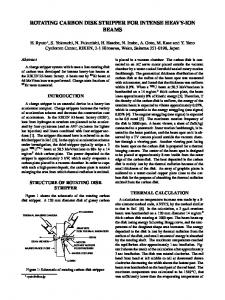
FIGURE CAPTIONS 1.
Calculated
quadrupole
electrode
edge of the beam, per
A longitudinal
assumed.
If
the 'electrodes
beam.then
the
2.
square
potential
of the
packing
are moved radially
(end view)
electrostatic
quadrupole Distortion
of
evident.
Transverse
motion
the
are shown by the for
Cs+l, of
co = 60" 2/3 is
away from
in proportion
3 MeV Cssl
of one quadrant
due to an elliptical
section.
is
fraction
at the
the to
aperture.
lines
tion
for
must be increased
Equipotential
envelope
required
ampere of current,
and u = 24'.
the
voltage
field
lines
of particles short
line
at 1 ampere.
of an beam cross
by space near
segments.
charge
is
the beam The calcula-
140
I
I
I
I
I
I
I
Quadrupole Focusing Voltage at Beam Edge per Ampere of Cl’
120 100 80 60 40
Phase Advance:
20 0 3 - 80
L
I
0
I
I
I
~=24O, q=60°, I
I
2 3 4 5 KINETIC ENERGY Fig. 1
I=IA I=0 I
I
6 (MeV)
7
8 3799A6
Fig. 2