Combining Dynamic Relaxation Method with Artificial Neural Networks to Enhance Simulation of Tensegrity Structures Bernd Domer1; Etienne Fest2; Vikram Lalit3; and Ian F. C. Smith, M.ASCE4 Abstract: Structural analyses of tensegrity structures must account for geometrical nonlinearity. The dynamic relaxation method correctly models static behavior in most situations. However, the requirements for precision increase when these structures are actively controlled. This paper describes the use of neural networks to improve the accuracy of the dynamic relaxation method in order to correspond more closely to data measured from a full-scale laboratory structure. An additional investigation evaluates training the network during the service life for further increases in accuracy. Tests showed that artificial neural networks increased model accuracy when used with the dynamic relaxation method. Replacing the dynamic relaxation method completely by a neural network did not provide satisfactory results. First tests involving training the neural network online showed potential to adapt the model to changes during the service life of the structure. DOI: 10.1061/共ASCE兲0733-9445共2003兲129:5共672兲 CE Database subject headings: Neural networks; Relaxation, mechanics; Tension structures; Simulation.
Introduction Cable structures and tensegrity structures, in particular, combine good load carrying capacity with low costs and aesthetics in unique ways. These qualities have been used to construct interesting structures, such as the Inland Revenue center in Nottingham 共Wakefield 1999兲, the 2002 World Cup Main Stadium 共Takenaka 2002兲, and the Georgia Dome 共Geiger 2002兲. In extension to cable structures, tensile forces of tensegrities do not need to be anchored. They are equilibrated by inner self-stress states. The most recent definition of tensegrity structures is given by Motro 共2002兲: ‘‘A tensegrity system is a structure in a stable, selfequilibrated state that contains a discontinuous set of components in compression inside a network of components in tension.’’ Tensegrity structures are complex. This is partly due to their geometrically nonlinear behavior. Of all possible analysis methods for tensegrity structures, the dynamic relaxation method has proven to be the most advantageous in terms of speed and robustness 共Barnes 1977, 1994兲. Dynamic relaxation is an iterative method which employs finite differences to converge to a static equilibrium position. Since revised node positions are part of the results, the method is useful for form finding 共Motro 1990兲 as well as for structural analysis 共Wakefield 1999兲. 1 Research Assistant, Structural Engineering Institute, IMAC-ISENAC, EPFL, 1015 Lausanne, Switzerland. 2 Research Assistant, Structural Engineering Institute, IMAC-ISENAC, EPFL, 1015 Lausanne, Switzerland. 3 Software Engineer, Geometric Software Solutions Company, Limited, Bombay, India. 4 Professor, Structural Engineering Institute, IMAC-IS-ENAC, 1015 Lausanne, EPFL, Switzerland. E-mail:
[email protected] Note. Associate Editor: Enrico Spacone. Discussion open until October 1, 2003. Separate discussions must be submitted for individual papers. To extend the closing date by one month, a written request must be filed with the ASCE Managing Editor. The manuscript for this paper was submitted for review and possible publication on June 24, 2002; approved on October 11, 2002. This paper is part of the Journal of Structural Engineering, Vol. 129, No. 5, May 1, 2003. ©ASCE, ISSN 0733-9445/ 2003/5-672– 681/$18.00.
Additionally, it has been shown that simple structural principles, such as Maxwell’s rule, cannot be applied to tensegrity systems 共Calladine 1978兲. The composition and analysis of an equilibrium matrix, which links nodal loads to member forces 共Pellegrino and Calladine 1986兲, provides deeper insights into the properties of such structures. Recent proposals discuss building intelligent structures through combining active structural control with tensegrity systems 共Smith and Shea 1999兲. To avoid control instabilities, the determination of control commands requires precise methods for predicting behavior. Experimental work has shown that the dynamic relaxation method accurately simulates the behavior of a full-size experimental structure in most cases 共Fest et al. 2003兲. Nevertheless, inaccuracies have been found when comparing measurements with calculated deflections. Such inaccuracies lower the effectiveness of the dynamic relaxation method for computational structural control. Material parameters have been determined through a testing program that was independent of the full-scale tests 共Fest et al. 2003兲. However, some parameters such as node friction and cable relaxation are difficult to quantify. This paper includes a proposal for the use of a neural network as an intermediate error– correction step between structural analysis results using the dynamic relaxation method and the results used for the determination of control commands. Artificial neural networks are useful for many applications in civil engineering 共Garrett et al. 1997兲. They are a simplified description of the human brain as a structural metaphor. A relation between an m-dimensional input vector and an n-dimensional output vector is established according to training examples. They have been used in structural engineering to predict the deformations of beams that are strengthened by carbon fiber reinforced plastic sheets 共Flood et al. 2000兲; to aid engineers during the conceptual stage of the design process 共Rafiq et al. 2000兲; and for structural optimization 共Kaveh and Iranmanesh 1998兲. Rehak and Garrett 共1992兲 envisioned the use of neural networks in structural control, while Zagar and Delic 共1993兲 have studied neural-
672 / JOURNAL OF STRUCTURAL ENGINEERING © ASCE / MAY 2003
Downloaded 12 Jun 2009 to 128.178.35.34. Redistribution subject to ASCE license or copyright; see http://pubs.asce.org/copyright
network control of the deflection of a bridge by predicting actuator commands. In contrast to these approaches, where neural nets are proposed to replace mechanical models or control formulations completely, this paper reports on a study of a combination of an established analysis method 共dynamic relaxation兲 with a neural net. More specifically, the objectives are to: • Review and verify the advantages of the dynamic relaxation method for the simulation of cable structures using a tensegrity structure as an example; • Determine whether correcting dynamic relaxation results using neural networks leads to increases in accuracy; • Train the neural network during service and quantify contributions to further increases in accuracy; and • Evaluate the potential for complete substitution of the dynamic relaxation method by a neural network.
Tensegrity Structures General Remarks Tensegrity structures consist only of compression 共bars兲 and tension 共cables兲 members, where cables surround bars. Buckminster Fuller has created the notion ‘‘Tensegrity’’ as a concatenation of the two words ‘‘tension’’ and ‘‘integrity’’ which has been patented 关B. Fuller ‘‘Tensile integrity structures,’’ U.S. Patent No. 3,063,521 共1962兲兴. The tension element provides the structure with a lightweight appearance. Therefore, Fuller characterizes these systems as ‘‘small islands of compression in a sea of tension.’’ In contrast with cable structures, tensile forces in tensegrity structures are controlled by inner self-stress states 共Motro 1992; Williamson and Skelton 1998兲. They are self-supporting and need no costly anchorages. Since they can be assembled and dismantled quickly, they are an attractive solution for temporary structures such as those used for fairs and expositions. When controlled actively, they have the added potential of becoming part of an exposition.
General Properties of Tensegrity Structures It has been shown by Calladine that Maxwell’s rule cannot be applied to determine whether a tensegrity system is stable 共Calladine 1978兲. Pellegrino and Calladine showed that the equilibrium matrix H can be used to determine properties of tensegrity structures 共Fig. 1兲 共Pellegrino and Calladine 1986兲. The equilibrium matrix describes the relation between the nodal loads and the member forces and provides information about structural properties such as the number of independent self-stress states and mechanisms. A self-stress state describes a state where the structure is in equilibrium because of unilateral element forces. The number of independent stress states, s, of a cable structure can be determined using the following equation: s⫽m⫺r
(1)
where m⫽number of links 共bars and cables兲 and r⫽rank(H). Mechanisms have to be distinguished in two categories: Infinitesimal and finite. Finite mechanisms allow node displacements without changing element length. Infinitesimal mechanisms describe nodal displacements where changes in element lengths are of lower order than changes in nodal displacements. In general, tensegrities have infinitesimal mechanisms. The number of mechanisms, q, is calculated as follows:
Fig. 1. Expressing the equilibrium of a structure in matrix form 关as presented in Pellegrino and Calladine 共1986兲兴
q⫽n⫺r
(2)
with n⫽3•J, 共where J⫽number of nonconstrained joints兲. Pellegrino and Calladine 共1986兲 showed further that the compatibility matrix C, which links nodal displacements and bar elongations, can be obtained simply by transposing the equilibrium matrix: C⫽HT
(3)
These expressions will be used in the section entitled ‘‘Tensegrity Structure’’ to evaluate the properties of a full-scale tensegrity module. In contrast with traditional structures composed of rigid materials, the shape of a tensegrity structure is not known in advance. Before initiating a formal structural analysis, a form finding step is necessary. This step, which consists in a search for the minimum surface between fixed points or borders, may be performed experimentally. For example, soap films have also been used for experimental form finding 共Fig. 2兲 共Bach et al. 1988兲. The surface tension of the soap film creates the smallest possible surface between fixed borders. Nevertheless, most form-finding tasks are performed analytically; this research employs the dynamic relaxation method, as described in the subsection entitled ‘‘Structural analysis with the dynamic relaxation method.’’ After form finding, forces and displacements of the tensegrity structure are calculated. Since this type of structure behaves nonlinearly, equilibrium conditions cannot be formulated on the undeformed system. For simple systems, such as a cable between two supports 共Fig. 3兲, an analytical solution is available. The system becomes stiffened only when it is deformed. For this case, the following expression relates loading and prestress 共Scharpf 1981兲 共see Fig. 4兲: P⫽
2w
冑
l 20 ⫹w 2
冋
N 0⫹
EA 共 冑l 20 ⫹w 2 ⫺l 0 兲 l0
册
(4)
JOURNAL OF STRUCTURAL ENGINEERING © ASCE / MAY 2003 / 673
Downloaded 12 Jun 2009 to 128.178.35.34. Redistribution subject to ASCE license or copyright; see http://pubs.asce.org/copyright
Fig. 4. Cable between two supports: Deformed state
Nonlinear behavior may be taken into account through adding the KNL stiffness matrix to the linear stiffness matrix K. The incremental Euler method solves this system of equations by applying NL the load, ⌬P, stepwise. The stiffness-matrix KL⫹K is iteratively reassembled to correct for deformations ⌬P⫽ 共 KL ⫹KNL 兲 •⌬␦
Fig. 2. Form finding with soap films 共Bach 1998兲
Simulation of Tensegrity Structures Form Finding with the Force Density Method The force density method has been proposed by Schek to determine possible shapes of equilibrium of a pin–jointed network consisting of cables and bars 共Schek 1973兲. It is stated that any state of equilibrium of a net structure can be obtained by solving a system of linear equations. The ratio between the branch forces and the branch lengths of the network is called force density. Given loading, support conditions, and force densities, the shapes of cable structures can be determined. Schek has also extended this method for other situations such as fixed force densities. Matrix and Vector Methods Analytical methods for the simulation of cable structures such tensegrity systems are classified as follows 共Barnes 1977兲: • Incremental methods; • Iterative methods; and • Minimization methods. Incremental and iterative methods use the matrix formulation finite elements. The approach consists in solving a system equations which links the stiffness matrix K with the vector loads P to obtain the structural deformations ␦ 共Szilard 1982兲 P⫽K•␦
as
Iterative methods, such as the Newton/Raphston method also employ Eq. 共6兲. However, instead of applying the load stepwise, the residual forces at the nodes are minimized during iterations. Although matrix methods generally require fewer iterations than minimization methods, nonsingular stiffness matrices are necessary. As a vector-based method, the dynamic relaxation method does not require such complexity. The dynamic relaxation method decouples equilibrium and compatibility until convergence to an equilibrium position is achieved. All methods include conditions in order to assure convergence. Since the stiffness relationships are represented separately, vector techniques are easier to accomodate 共Wakefield 1999兲. Structural Analysis with the Dynamic Relaxation Method The dynamic relaxation method is widely used for static structural analyses of cable structures. The method uses the dynamic equation of a damped system with an externally applied load to calculate the static behavior of structures 共Barnes 1977; Underwood 1983兲: P共 t 兲 ⫽Md¨⫹Cd˙⫹Kd
(5)
Fig. 3. Cable between two supports
(7)
The motion of the structural nodes is traced over time until the sum of residual forces in the nodes converges to a near ‘‘0’’ value. This indicates that the state of equilibrium of the structure has t been reached. The residual forces R i;(x,y,z) in each node i can be calculated by t ˙t Ri;t 共 x,y,z 兲 ⫽Mi; 共 x,y,z 兲 •V i; 共 x,y,z 兲 ⫹Ci; 共 x,y,z 兲 •Vi; 共 x,y,z 兲 ,
of of of
(6)
(8)
where V⫽vector of nodal velocities. Parameters to be set are the fictitious masses, m, and fictitious damping, c, that are represented in the matrices M and C of Eq. 共7兲 as well as the time step ⌬t. Papadrakakis 共1981兲 has compared several strategies for choosing these parameters in order to achieve rapid convergence. One of these strategies, kinetic damping, does not require determination of the viscous damping matrix C in Eq. 共8兲. The kinetic energy of the undamped structure is calculated, and whenever a kinetic peak is detected by a sudden fall of kinetic energy, the iteration steps back to the moment in time where the kinetic peak is assumed to have occurred. At this point, nodal velocities are reset to 0 and the current coordinates are taken as starting values for the next cycle of iterations. The strut element that was included in this analysis does not simulate buckling. Calculated compressive forces are checked against ultimate forces obtained by independent buckling tests.
674 / JOURNAL OF STRUCTURAL ENGINEERING © ASCE / MAY 2003
Downloaded 12 Jun 2009 to 128.178.35.34. Redistribution subject to ASCE license or copyright; see http://pubs.asce.org/copyright
Fig. 5. Tensegrity structure 共A, B, and C are supports兲
If necessary, material nonlinearity can be introduced at each time step, since no preassembled stiffness matrix is used. Whenever a cable receives a compressive force during one time step, its inner force is set to 0 for the subsequent step. Because the dynamic relaxation method calculates nodal displacements when calculating the member forces, a separate form-finding process is not necessary.
Tensegrity Structure Description of the Tensegrity Structure A tensegrity structure has been constructed at the Swiss Federal Institute of Technology 共EPFL兲 to perform research in the field of active structures 共Fig. 5兲. It consists of three modules. Each module includes the central node, where the three bars forming the upper pyramid are joined to the three bars forming the lower pyramid. 24 stainless-steel cables connect the 12 joints of each module. Bars are made of fiber reinforced polyester tubes in order to examine a new application for this material and to facilitate measurement of deformations. Analysis control software 共TSACS兲 has been developed. It uses the dynamic relaxation method 共S. Rossier, personal communication, February 21, 1994兲 to calculate forces and displacements of the system and provides graphical user interfaces for input and for results 共Fig. 6兲. According to Calladine, this tensegrity module fails the stability test when analyzed using Maxwell’s rule 共Calladine 1978兲. The rule states that 3• j⫺6
Fig. 6. One module 共screen shot from TSCACS兲
q⫽n⫺r⫽3•J⫺r⫽30⫺27⫽3 Since J is the number of nonconstrained joints. Initial prestress is applied to the structure when the telescopic bars are extended from their initial position. The notion of ‘‘2 mm prestress’’ means that all the bars have been uniformly extended by 2 mm more than their nominal initial length. Of several possible control objectives, maintaining the upper layer of the structure at a constant slope has been chosen as an initial research task 共Fig. 7兲. The slope is controlled by measuring the displacements of three nodes on the upper layer 共nodes 6, 52, and 62 in Fig. 7兲 and adjusting the telescopic bars such that they counteract displacements.
Coupling the Dynamic Relaxation Method with Neural Networks Perelli has shown that the dynamic relaxation method can be used to model this tensegrity structure 共Y. Perelli, personal communication, February 25, 2000兲. Input parameters for the calculation have been determined according to the materials used through independent testing 共E. Fest, personal communication, November 15, 1999兲. A discrepancy between theoretical calculations and
(9)
bars are needed for structural stability, where j⫽number of joints assuming a statically determinate structure in three dimensions. Applying this to one module, we calculate that 3•13⫺6⫽33 bars are needed to obtain static stability with Maxwell’s rule. In these modules, 30 bars and 13 joints provide static stability. Assembling the equilibrium matrix H results in a rank of 27. Thus, the number of independent self-stress states is calculated using Eq. 共1兲: s⫽m⫺r⫽30⫺27⫽3 The number of mechanisms for one module is calculated using Eq. 共2兲:
Fig. 7. Control objective involved maintaining the slope constant between nodes 6, 52, and 62. JOURNAL OF STRUCTURAL ENGINEERING © ASCE / MAY 2003 / 675
Downloaded 12 Jun 2009 to 128.178.35.34. Redistribution subject to ASCE license or copyright; see http://pubs.asce.org/copyright
measured behavior has been observed. Although this might be acceptable for isolated calculations, errors may accumulate throughout a sequence of control commands under active control. Node friction, cable relaxation, node deformation, and changing environmental conditions are possible causes for differences between measured and predicted behavior. Values of these parameters are difficult to determine accurately 共Fest et al. 2003兲. The next section discusses the potential for neural networks to increase the accuracy of the dynamic relaxation method since they are able to model nonlinear relationships and are known to be efficient when applied to time-variant systems 共Garrett et al. 1997兲.
During the training phase, sets of known input/output patterns are processed. The weights of the internodal connections are adjusted to match the desired output. Adjustments may be made by propagating back the error that is calculated as the difference between the output layer and the desired output. The factor that governs the amount of change in each node of the network during the backpropagation is called the learning rate ( j ). Since the sigmoid function is insensitive to input values greater than two, the input vector should be normalized to an interval of 关0,1兴. For a more detailed description of neural networks, see Pfeiffer and Scheier 共1999兲 and Rojas 共1996兲.
Neural Networks
Stuttgart Neural Net Simulator
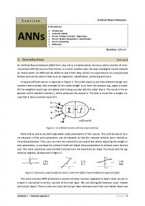
Description Artificial neural networks establish relationships between m-dimensional input vectors and n-dimensional output vectors. Such relationships are particularly useful when no mathematical formulation is available. The core component of a neural net is the neuron or node. Nodes are used to connect the input layer, hidden layers, and the output layer. The nodes of hidden layers and the output layer receive input from the previous layer 关 ␣ i in formula 共10兲兴. This input is multiplied by the weight, w i, j , of each internodal connection and summed up. The total activation of the node, x j , is then calculated by subtracting the internal threshold, T j , from this sum x j⫽
兺 w i, j •␣ i ⫺T j
(10)
x j is passed to the transfer function of the node, F, which determines the final output, o j . For transfer functions 共for the continuous and monotonic functions of a neural net兲, the sigmoid function is chosen f 共 x 兲⫽
1 1⫹e ⫺x
(11)
A wide choice of software exists for creating and testing neural networks. A particularly useful tool is the Stuttgart Neural Net Simulator 关共SNNS兲 2001兴. A graphical user interface helps design the network and offers a choice of learning methods and activation functions. For more sophisticated tasks, a batch language may be used. The batch processor ‘‘batchman’’ processes small programs. Within the scope of this project, the graphical interface of SNNS has been used to create network topologies. Batchman was employed for training and testing the networks.
Tests Test Description The primary focus in testing was to determine whether using a neural network can increase the accuracy of the dynamic relaxation method when used alone 共Y. Perelli, personal communication, April 25, 2000兲. Previous tests measured the displacement of three nodes on the upper layer of the structure. 90 pattern sets consist of displacements calculated using the dynamic relaxation method and three measured displacements. Magnitudes and loca-
Table 1. Magnitudes and Location of the Loading Joint loaded
Prestress 共mm兲
Symmetric
6, 52, 62 5, 48, 61
2 2
152, 388, 623, 860 152, 388, 623, 860
Asymmetric
6 52 62 5 48 61
2 2 2 2 2 2
152, 152, 152, 152, 152, 152,
388, 388, 388, 388, 388, 388,
623, 623, 623, 623, 623, 623,
Central joint
7 54 63 7 54 63 7 54 63 7, 54, 63
2 2 2 3 3 3 4 4 4 2
152, 152, 152, 388, 388, 388, 388, 388, 388, 152,
388, 388, 388, 860, 860, 860, 860, 860, 860, 388,
623, 860, 981, 623, 860, 981, 623, 860, 981, 1,216, 1,687 1,216, 1,687 1,216, 1,687 1,216, 1,687 1,216, 1,687 1,216, 1,687 623, 860, 981,
Type
Loads applied 共N兲
860 860 860 860 860 860 1,216, 1,452, 1,687, 1,923 1,216, 1,452, 1,687, 1,923 1,216, 1,452, 1,687, 1,923
1,216, 1,452
676 / JOURNAL OF STRUCTURAL ENGINEERING © ASCE / MAY 2003
Downloaded 12 Jun 2009 to 128.178.35.34. Redistribution subject to ASCE license or copyright; see http://pubs.asce.org/copyright
Table 2. Comparison of Four Network Topologies Network
Test error 共sum of square error兲
3-8-3 3-12-3a 3-10-10-3 3-14-14-3
8.10E⫺02 7.98E⫺02b 8.09E⫺02 7.87E⫺02b
a
The two best networks are studied further in Fig. 9. Used for evaluation with unseen data.
b
Fig. 8. Node numbers of loaded joints, corresponding to Table 1
tions of the loading that lead to these pattern sets are presented in Table 1 and Fig. 8. Load cases are subdivided into three classes: symmetric, asymmetric, and central joint loading. Symmetric loading applies the same load magnitude to nodes whose combined center of gravity corresponds to the center of gravity of the structure. Asymmetric loading involves one edge node at a time, and central joint loading means that the central joints of each module are loaded. Since the neural network is ultimately intended to be used for active control, results from a range of prestress levels were employed. Measurements were taken three times to exclude errors. This results in a total number of 270 pattern sets. As described in the section entitled ‘‘Description of the Tensegrity Structure,’’ three nodes on the upper layer were used as reference points for slope control. Therefore, the goal of this work was to increase the accuracy of calculating deflections at these three nodes. This goal thus fixed the number of input and the number of output nodes of candidate networks to three each. The number of nodes in the hidden layer was evaluated initially for 12 network topologies having zero, one and two hidden layers. The results of these tests indicated that four topologies had potential, and they were subsequently employed for the main testing phase. These topologies were: • 3-8-3; • 3-12-3; • 3-10-10-3; and • 3-14-14-3. The first and last numbers indicate numbers of nodes in the input and output layer 共three in every case兲. Numbers between the first and last numbers provide the number of nodes in the hidden layers. All networks being used were feed forward and used the sigmoid transfer function. The learning rate was set to ⫽0.2. Throughout all tests, pattern sets were subdivided into training, testing, and unseen patterns. As their name indicates, training patterns were used to train the network. The weights of the network were changed after each training cycle to minimize the training error. After every 100 training cycles, the test patterns were presented to the trained network, and the test error was evaluated. Weights were only saved when the testing error decreased. It was observed that training errors decreased continually, but test errors started to increase after some time. This is due to the fact that neural networks may overcorrelate training patterns when they have been subjected to too many training cycles.
Unseen patterns were used after training and testing of the network to check overall generality. A batch program was written using the SNNS batch interpreter for training and testing the four network topologies. One-layer networks were trained for at most 500,000 cycles and the twolayer networks for up to 1,500,000 cycles. The error used is the sum of square error, which is equal to the sum of the square of the difference between normalized simulated and normalized targeted values. In addition to primarily focusing on determining the potential accuracy enhancement, two other applications of neural networks have been tested: 1. Examining the possibilities of online training to adapt the neural net to changing loads and environmental conditions; and 2. Compare correcting the dynamic relaxation method results with complete replacement by a neural network.
Enhancing the Accuracy of the Dynamic Relaxation Method Using Measured Results A total number of 270 patterns were available. The usual experimental procedure of eliminating unrealistic data resulted in the deletion of 30 patterns. The remaining 240 have been subdivided into three groups as follows: 1. Training patterns: 150; 2. Test patterns: 39; and 3. Unseen patterns: 17. Training of the four network topologies and subsequent testing reveals test errors that are given in Table 2. Finally, unseen patterns are tested against tripled targeted values allowing 17 comparisons. This has been carried for the 3-12-3 and the 3-14-14-3 topology and the results are shown in Fig. 9. In Fig. 9, deviations of simulated values from the targeted measured values are compared by calculating ratios of results when using neural networks (DR⫹NN) for an additional error correction step and when using
Fig. 9. Accuracy loss for the 3-12-3 and the 3-14-14-3 topology JOURNAL OF STRUCTURAL ENGINEERING © ASCE / MAY 2003 / 677
Downloaded 12 Jun 2009 to 128.178.35.34. Redistribution subject to ASCE license or copyright; see http://pubs.asce.org/copyright
Table 3. Comparison of Four Network Topologies Trained with the
Average of Data Triples Network
Test error 共sum of square error兲
3-8-3 3-12-3 3-10-10-3 3-14-14-3
5.80E⫺03 6.05E⫺03 5.24E⫺03 5.79E⫺03
only the dynamic relaxation method 共DR兲 for simulation. Values above the ‘‘1’’ axis represent, therefore, an increase; values below 1 represent a decrease in accuracy when using a neural network. The best network 共3-12-3兲 only increases accuracy in 3 out of 17 cases 共13,15,16兲. In all other cases, there are losses in accuracy. It can be concluded that training the networks with these data sets does not contribute to the overall accuracy of the simulation. This observation also is clear when values of the average increase in accuracy are calculated 共continuous and dotted lines in Fig. 9兲 since they are less than one. Using the Average of the Measured Values Since the initial choice of the training and testing patterns did not give encouraging results, and since each load case was tested three times, averages of these three test results were calculated. This resulted in a total of 80 patterns and these were subdivided into 50 training, 13 test, and 17 unseen patterns. The evaluation of the four network topologies identified the 3-8-3 and the 3-10-10-3 networks 共Table 3兲. Using the same scheme as in Fig. 9 to present the results, Fig. 10 shows the evaluation of the unseen patterns. The situation has changed drastically: Now, there is only one data set out of 17 共in the 3-10-10-3 configuration兲 which shows a decrease in accuracy. The decrease of accuracy 共15.75%兲 is a tolerable value, which is not expected to affect the stability of the structure in practice. Fig. 11 is a plot of the ratio of improvements of accuracy in Fig. 10 for each unseen pattern. Values above the 1 axis indicate cases where the two-layer network performed better than the onehidden layer network. The two-hidden layer network is more advantageous than the one-hidden layer network. Using Jenkin’s Hypercube for the Selection of Training Data The results in Figs. 9 and 10 demonstrate that training data characteristics affect the ability of the net to generalize. If too little data are used, the network will not be able to give a reasonable approximation. On the other hand, if too much data are presented,
Fig. 10. Accuracy enhancement for the 3-8-3 and the 3-10-10-3 topology
Fig. 11. Comparison of the two-layer/one-layer configuration
the network could model this data ‘‘too closely’’ 共overconditioning兲; thus, it would not be able to generalize to other data. Modeling relationships beyond the scope of the training patterns is difficult for statistical methods such as neural networks. Therefore, input–output training patterns should contain data that correspond to even distributions between the borders of spaces of possible values. Jenkin’s hypercube concept evaluates data to determine whether the solution space is covered to the greatest possible extent 共Jenkins 1997兲. The minimal number of training data needed depends on the number of output nodes. For example, three-output nodes demand a three-dimensional 共3D兲 hypercube. A 3D cube can be easily visualized and consists of 27 significant points since there are corners, midsides, midfaces, and a center 共Fig. 12兲. Unfortunately, the measurement data that are available in this study do not coincide with the optimal distribution described by Jenkin’s hypercube. This is understandable since results are determined by specific loading configurations and the physical principles of structural behavior. Although its main focus is to indicate the best distribution of training patterns, the model can be used to reduce the number of pattern sets needed for training. The focus of this test was to determine the potential for further reductions in the number of training patterns needed. Therefore, two different testing and training pattern sets have been created: One by considering the hypercube concept 共pattern set ‘‘A’’兲, the other by randomly choosing patterns 共pattern set ‘‘B’’兲. The minimal number of 27 patterns has been used in both cases. The 3-8-3 and 3-10-10-3 network configurations have been trained with pattern set A as well as with pattern set B. All networks have been tested using the same unseen patterns as in the subsection entitled ‘‘using measured results.’’ Accuracy decreased to unacceptable values in both cases.
Fig. 12. Hypercube 关as presented in Rafiq et al. 共2000兲兴
678 / JOURNAL OF STRUCTURAL ENGINEERING © ASCE / MAY 2003
Downloaded 12 Jun 2009 to 128.178.35.34. Redistribution subject to ASCE license or copyright; see http://pubs.asce.org/copyright
Online Training Online training enables modification of neural nets when environmental conditions change. Active tensegrity structures in practical situations could use such functionality. Online training consists of, first, adding new measurements taken during the service life of the structure to the training data and, second, retraining the network. Since computational time can be excessively long during service, the training time needed for the network becomes an important issue. In an initial study, the most promising network topologies from the section entitled ‘‘Enhancing the Accuracy of the Dynamic Relaxation Model’’ were chosen: The one-layer 共3-8-3兲 configuration and the two-layer configuration 共3-10-10-3兲. The networks that have already been trained with 19 pattern sets have been trained for three further cycles. In each cycle, one pattern set has been added to the training data. This results in a total number of 20, 21, and 22 patterns for the first, second, and third set. The network is then trained until the test error starts increasing and are than trained for an additional 10 s. The error decreased by 1.9% for the 3-8-3 configuration and by 0.55% for the 3-10-10-3 configuration. These decreases are not large enough to warrant such functionality at this time. Further work is required to determine the characteristics of the most useful training sets.
Substituting the Dynamic Relaxation Method Completely with Artificial Neural Networks The present model uses the dynamic relaxation method in combination with a neural network to calculate the nodal displacements of the tensegrity structure. It could be argued that one neural network might be able to completely replace the dynamic relaxation method. This would save much computational time. As a first step, it was checked whether the dynamic relaxation method could be replaced by a neural network. This has been tested using data taken from analysis results. When all 33 nodes of the three-module structure are modeled, an extremely complex network follows. Complexity increases exponentially with the addition of modules. Test data were generated analytically for a network where the dead load was constant and the structure was loaded at one point. Starting with three nodes in the input layer and one node in the output layer, the network has been trained for 60,000 epochs. A 3-8-8-1 configuration has been used. Although a sufficiently low training error was attained, the test patterns are further away from the desired output 共Fig. 13兲. Until now, the sigmoid function has been used as an activation function with normalized values between 关0;1兴. The tan hyperbolic function has been chosen to enlarge the bandwidth and normalization between ⫺1 and ⫹1; therefore, allowing a more precise normalization. More training patterns than used in previous tests have been generated. As Fig. 14 shows, the deviations increased dramatically. Further tests have been performed using another method of normalizing input data as well as with other network topologies 共3-8-8-3 and 3-12-12-3兲. None revealed satisfactory results.
Fig. 13. Percentage deviations for the test patterns 共3-8-8-1 network, sigmoid activation function兲
clearly better than the use of neural nets alone. Other types of neural networks exist and might show advantages over the one used. Additional training patterns are needed for further decreases of the overall error. The measurement data, which has been used for the training of the neural network, is related to the configuration of the structure. Future work involves studying to what extent the neural network can be used to correct analysis of structure with more than three modules, different geometries, and materials. In exceptional cases where the neural net is not able to increase accuracy, its use is not expected to affect the reliability of the model for iterative active control. Although the strategy of selecting training data according to a hypercube configuration has been used successfully for other applications, its implementation is complicated by distribution characteristics of the measurement data. A hypercube distribution might, nevertheless, prove to be a useful filtering strategy when the structure is controlled actively, since large numbers of measurements will become available. Online training may be useful for further increasing the precision of the model and for adapting the neural net to changing environmental conditions. Although the improvement of 1.9% does not yet justify implementation, there is potential for further enhancements. This functionality requires further investigation. The following issues are examples of important aspects: • Evaluation of the quality of the training pattern proposed by the measurement system; and • Deletion of old pattern sets without affecting accuracy.
Discussion and Conclusions Artificial neural nets provide a useful complement to simulation using the dynamic relaxation method. Even when used with sparse training data, they lead to increased model precision while maintaining explicit structural knowledge. Such a combination is
Fig. 14. Percentage deviations for the test patterns 共3-8-8-1 network, tanh activation function兲 JOURNAL OF STRUCTURAL ENGINEERING © ASCE / MAY 2003 / 679
Downloaded 12 Jun 2009 to 128.178.35.34. Redistribution subject to ASCE license or copyright; see http://pubs.asce.org/copyright
These aspects are similar to concepts of case-based reasoning and case maintenance 共Smyth and Keane 1995兲. Several network configurations using various activation functions and methods for normalization of input values have been studied—no justification for the complete replacement of the dynamic relaxation method with a neural network could be found. The principle conclusions of this study are as follows: 1. Neural networks enhance the accuracy of the simulation of tensegrity structures; 2. Replacing dynamic relaxation with a neural networks is not justified; and 3. Although online training has potential, further work is needed to justify its use. This study provides important contributions to the implementation of actively controlled tensegrity structures.
Acknowledgments This research was partially funded by the Swiss National Science Foundation No. 2000-061756. The writers gratefully acknowledge the suggestions of Ashok Gupta 共IIT Delhi兲, which led to test whether the dynamic relaxation method can be completely replaced by neural networks. They would like to thank Dr. Alan Kwan, Cardiff University of Engineering, Dr. Benny Raphael for discussions, and Yann Perelli for performing some of the experiments.
Notation The following symbols are used in this paper: A ⫽ area; C ⫽ damping matrix; d ⫽ vector of nodal displacements; E ⫽ module of elasticity; H ⫽ equilibrium matrix of cable structures; J ⫽ number of nonconstrained joints; K,K1 ⫽ stiffness matrix; KNL ⫽ nonlinear stiffness matrix; M ⫽ mass matrix; m ⫽ number of links 共bars and cables兲 of cable structures; P ⫽ single load; P(t) ⫽ vector of nodal forces, varying with time; q ⫽ number of mechanisms; R ⫽ vector of residual forces; r ⫽ rank of equilibrium matrix H; s ⫽ stress states of cable structures; V ⫽ vector of nodal velocities; w ⫽ deflection; and ␦ ⫽ deformation.
References Bach, K., Burkhardt, B., and Otto, F. 共1988兲. ‘‘Seifenblasen Bubbles, IL 18.’’ Universita¨t Stuttgart, Institut fu¨r leichte Fla¨chentragwerke, Karl Kra¨mer Verlag, Stuttgart. Barnes, M. R. 共1977兲. ‘‘Form finding and analysis of tension space structures by dynamic relaxation.’’ PhD thesis, The City University of London.
Barnes, M. R. 共1994兲. ‘‘Form and stress engineering of tension structures.’’ Struct. Eng. Rev., 6共3– 4兲, 175–202. Calladine, C. R. 共1978兲. ‘‘Buckminster Fuller’s ‘‘tensegrity’’ structures and Clerk Maxwell’s rules for the construction of stiff frames.’’ Int. J. Solids Struct., 14, 161–172. Fest, E., Shea, K., Domer, B., and Smith, I. F. C. 共2003兲. ‘‘Adjustable tensegrity structures.’’ J. Struct. Eng., in press. Flood, I., Nandy, S., and Muscynski, L. 共2000兲. ‘‘Assessing external reinforcement on RC beams using neural nets.’’ Proc., Computing in Civil and Building Engineering, ICCCBE-VIII, August 14 –16, Stanford, CA, ASCE Publication, 1114 –1120. Garrett, J. H. Jr., Gunaratnam, D. J., and Ivezic, N. 共1997兲 ‘‘Introduction.’’ N. Kartam, I. Flood, and J. H. Garrett, Jr., eds.: Artificial Neural Networks for Civil Engineers: Fundamentals and Applications, ASCE Publication, 1–18. Geiger 共2002兲. ‘‘Tensile membrane projects.’’ 具http:// www.geigerengineers.com典 共May 2002兲. Jenkins, W. M. 共1997兲. ‘‘Approximate analysis of structural grillages using a neural network.’’ Proc. Inst. Civ. Eng., Struct. Build., 122, 355–363. Kaveh, A., and Iranmanesh, A. 共1998兲. ‘‘Comparative study of backpropagation and improved counterpropagation neural nets in structural analysis and optimization.’’ Int. J. Space Struct., 13共4兲, 177–185. Motro, R. 共1990兲. ‘‘Tensegrity systems and geodesic domes.’’ Int. J. Space Struct., 5共3– 4兲, 341–351. Motro, R. 共1992兲. ‘‘Tensegrity systems: The state of the art.’’ Int. J. Space Struct., 7共2兲, 75– 83. Motro, R. 共2002兲. ‘‘Tensegrity: The state of the art.’’ Proc., Space Structures 5, University of Surrey, Thomas Telford publishing, Guildforth, 97–106. Papadrakakis, M. 共1981兲. ‘‘A method for the automatic evaluation of dynamic relaxation parameters.’’ Computer Methods in Applied Mechanics and Engineering, Vol. 25, North–Holland, Amsterdam, 35– 48. Pellegrino, S., and Calladine, C. R. 共1986兲. ‘‘Matrix analysis of statically and kinematically indeterminate frameworks.’’ Int. J. Solids Struct., 22共4兲, 409– 428. Pfeiffer, R., and Scheier, C. 共1999兲. ‘‘Neural networks for adaptive behavior.’’ Understanding intelligence, MIT Press, Cambridge, MA, 139–177. Rafiq, M. Y., Bugmann, G., and Easterbrook, D. J. 共2000兲. ‘‘Artificial neural networks to aid conceptual design.’’ Struct. Eng., 78共3兲, 25–32. Rehak, D. R., and Garrett, J. H. Jr. 共1992兲. ‘‘Neural computing for intelligent structural systems.’’ Intelligent structures 2, Y. K. Wen, ed., Elsevier Science, New York, 147–161. Rojas, R´. 共1996兲. Neural networks - A systematic introduction, Springer, Heidelberg. Scharpf, D. 共1981兲. ‘‘Zur Berechnung von Seiltragwerken.’’ Berichtsband zur Vortragsveranstaltung Seile und Bu¨ndel im Bauwesen, Beratungsstelle fu¨r Stahlverwendung, Du¨sseldorf, III.1-1–13. Schek, H. J. 共1973兲. ‘‘The force density method for form finding and computation of general networks.’’ Computer methods in applied mechanics and engineering 3, North–Holland, Amsterdam, 115–134. Smith, I. F. C., and Shea, K. 共1999兲. ‘‘Extended active control to build intelligent structures.’’ Proc., Structures for the Future- The Search for Quality, IABSE Reports, Vol. 83, International Association for Bridge and Structural Engineering, Zurich, 1057–1064. Smyth, B., and Keane, M. T. 共1995兲. ‘‘Remembering to forget.’’ Proc., 14th Int. Joint Conf. in Artificial Intelligence, Montreal, Canada, Morgan Kaufmann, San Mateo, 377–382. Stuttgart Neural Net Simulator 共SNNS兲. 共2001兲. ‘‘Stuttgart Neural Net Simulator.’’ 具http://www-ra.informatik.uni-tuebingen.de/SNNS/典 共May 2002兲. Szilard, R. 共1982兲. ‘‘Finite Berechnungsmethoden der Strukturmechanik.’’ Band 1: Stabwerke, Ernst and Sohn, Berlin. Takenaka 共2002兲. ‘‘Cable structures.’’ 具http://www.takenaka.co.jp/ takenaka e/dome e/history/tech/cable.html典 共May 2002兲.
680 / JOURNAL OF STRUCTURAL ENGINEERING © ASCE / MAY 2003
Downloaded 12 Jun 2009 to 128.178.35.34. Redistribution subject to ASCE license or copyright; see http://pubs.asce.org/copyright
Underwood, P. 共1983兲. ‘‘Dynamic relaxation.’’ Computational methods for transient analysis, T. Belytschko, and T. J. R. Hughes, eds., Elsevier Science, New York, 246 –265. Wakefield, D. S. 共1999兲: ‘‘Engineering analysis of tension structures: theory and practice.’’ Engineering structures 21, Elsevier Science, New York, 680– 690.
Williamson, A., and Skelton, R. 共1998兲. ‘‘A general class of tensegrity systems.’’ Proc., Engineering Mechanics for the 21st Century, ASCE Conference, La Jolla, California, May 17–20, 1–7. Zagar, Z., and Delic, D. 共1993兲. ‘‘Intelligent computer integrated structures: A new generation of structures.’’ Advanced technologies, Elsevier Science, New York, 371–378.
JOURNAL OF STRUCTURAL ENGINEERING © ASCE / MAY 2003 / 681
Downloaded 12 Jun 2009 to 128.178.35.34. Redistribution subject to ASCE license or copyright; see http://pubs.asce.org/copyright