Compact Automotive Optical Current Sensor Based on Evanescent-Wave Scattering by Ferromagnetic Particles Binghui Li, Hau Ping Chan, Kazi Tanvir Ahmmed, Zhe Huang Department of Electronic Engineering, City University of Hong Kong, Hong Kong, China
[email protected]
Abstract: A compact optical sensor is proposed for automotive current monitoring. Dynamic sensitivity of 0.0357 dB/mA is achieved with good linearity. Multiple sensor outputs can be transmitted through a single fiber by wavelength-division-multiplex scheme. OCIS codes: (280.4788) Optical sensing and sensors; (130.5460) Polymer waveguides. (290.5850) Scattering, particles.
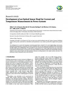
1. Introduction Accurately monitoring current flow in a vehicle is crucial for control of motor drives, overcurrent protection and monitoring of charge batteries [1]. In view of non-destructive, electric isolation and fast response, optical current transducers (OCT) draw much attentions since the report of Faraday-rotation based fiber current sensor (OCS) [2]. These techniques indeed show good performance in current transducing, however most of them either require specific materials, complex platforms, or expensive follow-up analytical facilities. Besides that, some methods show weakness in space-occupation, such as fiber current sensors based on Faraday-effect requires long fiber length and large bending diameter to reduce birefringence, which is inappropriate in automotive use. In this report, we propose a simple intensity-interrogated optical platform for current monitoring based on scattering of evanescent waves by manipulating the movement of ferromagnetic carbonyl-iron particles (CIP), Compared to other techniques, we highlight the way of manipulating ferro-particles for achieving current sensing. This sensing platform employs the advantages of compact-in-size, easy implementation, good integratability, potentially low cost, and offering real-time A.C. / D.C. current monitoring. 2. Sensing principle The basic principle is to scatter the evanescent waves propagating along a liquid-cladded channel-waveguide by a mass of ferro-particle clusters as shown in Fig. 1(a). Here, the clusters are formed by particle-aggregation under external magnetic field, which then further attach onto a magnetized blade-edge. The blade edge is placed parallel to the waveguide channel. Fig. 1(b) illustrates the idea with a simplified 2D cross-sectional view, where the light propagates in z-direction (into the paper). Mathematically, the force exerted on a small ferro-particle in the nonuniform magnetic field is given by [3]: where m and B represent the magnetic moment and the magnetic flux density experienced by the ferro-particle. (a)
(b)
Fig. 1. (a) Formed ferro-particle clusters on a magnetized blade. (b) Schematic diagram of sensing principle. Current-induced magnetic force draw down the columns towards the waveguide surface.
This equation illustrates that the magnetic force will drive the particles towards higher B-field. As shown in Fig. 1(b), we put a coil behind the waveguide structure pointing towards the blade. When the current passing through the coil increases, the induced magnetic force will increase, hence drawing the iron particles column closer towards the point “O” as indicated by the arrows. Consequently, this leads to a closer distance between the iron particles and the
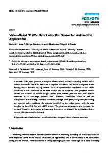
waveguide surface. Under this situation, the waveguide evanescent field will be more disturbed by the iron columns. Likewise, if current is reduced, the column tends to return to the initial position like a spring due to magnetic repulsion. Thus, the disturbance on the evanescent field by the vicinal iron columns will increase. To further illustrate quantitatively the scattering effect of ferro-particles to the transmission loss of a channel waveguide when in close proximity, we create a model in Lumerical FDTD solutions and simulate the transmission loss versus different locations of a ferro-particle moving synchronously from point “A” to point “B” as shown in Fig. 1(b), with the horizontal range between t = [0, 3.5] um and vertical range d = [0, 1.4] um. The simulation result indicates only a single particle is enough to induce 5% loss in transmission, which can be further increases with increase number of ferro-particles used. 3. Experimental Set-up Fig. 2(a) shows the testing platform to illustrate our design. The light from a stabilized DFB source is coupled into a liquid-cladded channel waveguide and its output power is measured by a power meter. The coil is feeding with a sinusoidal A.C. current biased at a preset D.C. current, and the total instantons current through the coil is monitored by an oscilloscope. The coil will then generated an alternating B-field pointing perpendicularly towards waveguide. The blade will hold the particle clusters for offering a sensing region of around 5 mm. TEC is adopted for temperature stabilization during the experiment. However, this may not be necessary through proper choice of waveguide materials and design. In practice, the optical output of the sensor can be coupled to an optical fiber directly for distribution of the signal. If multiple sensor units shown Fig. 2(a) are needed, each individual sensor output can be easily multiplexed into a single transmission fiber using wavelength division multiplex (WDM) scheme.
Fig. 2. (a) Schematic diagram of design. (b) Real-time data of light output versus input current. (c) AC measurement results at different positions.
4. Results and discussion To investigate the dynamic performance of the sensor, we applied a 50Hz AC signal biased with 0.1A DC current to the sensing coil. Fig. 2(b) shows the real time response of the sensor output (blue line) for the corresponding input current (black line). In general, a fairly good linearity can be seen. To further investigate the sensitivity of the sensor at different vertical gap distance d, we define two different particle position “A” and “B”. Position B had a smaller gap distance than position A. Fig. 2(c) shows that tunable sensitivity from A to B is achieved. Both position A and B show good linear intensity response versus current input. By linear data-fitting, the AC current sensitivity can be calculated as 0.0105 dB/mA for position A and 0.0357 dB/mA for position B. Compared with previous report [4], our design illustrates 2 times higher in sensitivity, however only occupies 1/50 in sensing length. With our design, other types of sensor, such as ultra-sensitive displacement sensor, can also be easily achieved, for example, by correlating the gap distance with the sensor output. 5. Conclusion In this report, a compact intensity-interrogated optical sensing platform for automotive current monitoring is proposed. This basic principle is to scatter the evanescent waves propagating along a liquid-cladded channel-waveguide by a mass of ferro-particle clusters. Experimental results shows the AC sensitivity up to 0.0357 dB/mA is obtained with good linear response. Moreover, this design illustrates advantages of good integratability, simple structure and ease of operation. In addition, the output signals of multiple sensors can be easily multiplexed into a single transmission fiber using wavelength-division-multiplex scheme. Reference [1] Leen G, Heffernan D. “Expanding automotive electronic systems.” Computer, 35, 88-93 (2002). [2] Saito, S., et al. "Developments of the laser current transformer for extra-high voltage power transmission lines." IEEE J. Quant. 3 266 (1967). [3] Cohen R E, Lide D, Trigg G. Physicist's Desk Reference. Springer Science & Business Media, (2003). [4] Wang S F, Chiang C C.“A notched long-period fiber grating magnetic field sensor based on nanoparticle magnetic fluid.” Appl. Sci, 6 (2016).