2.1.4 Phase diagrams of Cu2ZnSnSe4 . ...... from classical ions in the typical molten salts to charged polyatomic molecules in ionic liquids. The prototype of ..... monograin powders on the sieving machine followed by a manual sieving. ...... (33) A Walsh, S Chen, X. Gong , S Wei , Crystal structure and defect reactions in the.
TALLINN UNIVERSITY OF TECHNOLOGY Faculty of Chemistry and Materials Technology Department of Materials Science Chair of Semiconductor Materials Technology
Comparative Study of Cu2ZnSnSe4 Monograin Powder Synthesis in Different Molten Salts Master Thesis
JOHN ADEOLA ADEGOKE
Supervisor: Kristi Timmo, Senior Research Scientist Chair of Semiconductor Materials Technology
Materials and Processes of Sustainable Energetics KAYM09 TALLINN 2015
TALLINNA TEHNIKAÜLIKOOL Keemia- ja materjalitehnoloogia teaduskond Materjaliteaduse instituut Pooljuhtmaterjalide tehnoloogia õppetool
Monoterapulbrilise Cu2ZnSnSe4 sünteeskasvatuse võrdlus erinevates sulades soolades Magistritöö
JOHN ADEOLA ADEGOKE
Juhendaja: Kristi Timmo, Vanemteadur Pooljuhtmaterjalide tehnoloogia õppetool
Materjalid ja protsessid jätkusuutlikus energeetikas KAYM09 TALLINN 2015
2
Declaration
Hereby, I declare that this master thesis, my original investigation and achievement, submitted for the master degree at Tallinn University of Technology has not been submitted for any degree or examination.
.................................. (Author’s signature
3
Table of contents Table of contents ..................................................................................................................................... 4 List of abbreviations and symbols ........................................................................................................... 6 1.
INTRODUCTION ............................................................................................................................... 7
2.
LITERATURE REVIEW ....................................................................................................................... 9 2.1 Principle of solar cells .................................................................................................................... 9 2.1.1 Review of solar cells absorber materials .............................................................................. 10 2.1.2 Kesterite based solar cells .................................................................................................... 12 2.1.3 Crystal structure and defect studies in kesterites ................................................................ 13 2.1.4 Phase diagrams of Cu2ZnSnSe4 ............................................................................................. 14 2.1.5 Review of Cu2ZnSnSe4 thin film fabrication .......................................................................... 16 2.2 Monograin powder technology ................................................................................................... 17 2.2.1 Overview............................................................................................................................... 17 2.2.2 Monograin powder growth .................................................................................................. 17 2.2.3 Formation of Cu2ZnSnSe4 ..................................................................................................... 18 2.2.4 Flux materials ....................................................................................................................... 19 2.2.5 Chemical interactions between Cu2ZnSnSe4 and flux materials .......................................... 21 2.2.6 Monograin layer solar cells .................................................................................................. 22 2.3 Analytical methods ...................................................................................................................... 23 2.3.1 Scanning electron microscope ............................................................................................. 23 2.3.2 Energy dispersive X-ray spectroscopy .................................................................................. 24 2.3.3 Raman spectroscopy ............................................................................................................ 24 2.3.4 Sieving analysis ..................................................................................................................... 25 2.4 Summary of literature overview and the objective of the study ................................................ 25
3.
EXPERIMENTAL .............................................................................................................................. 27 3.1 Degassing process of flux materials ............................................................................................ 27 3.2 Preparation of monograin powders ............................................................................................ 27 3.3 Characterization of monograins .................................................................................................. 30
4.
RESULTS AND DISSCUSION ............................................................................................................ 31 4.1 The yield of material.................................................................................................................... 31 4.2 Particle size distribution .............................................................................................................. 32
4
4.3 Elemental composition of Cu2ZnSnSe4 monograin powders....................................................... 38 4.4 Phase composition of Cu2ZnSnSe4 monograin powders ............................................................. 39 4.5 Morphology of Cu2ZnSnSe4 monograin powders ........................................................................ 47 CONCLUSIONS ....................................................................................................................................... 51 ABSTRACT .............................................................................................................................................. 53 RESÜMEE ............................................................................................................................................... 55 REFERENCES .......................................................................................................................................... 57 ACKNOWLEDGEMENTS ......................................................................................................................... 62
5
List of abbreviations and symbols PV
Photovoltaic
CdTe
Cadmium telluride
CIGSe
Cadmium indium Gallium selenide
a-Si
Amorphous Silicon
CZTSe
Copper zinc tin selenide
CZTS
Copper zinc tin sulphide
TUT
Tallinn University of technology
Eg
Band gap
CdS
Cadmium Sulphide
ΔHf
Heat of formation
MGL
monograin layer
MS
Mass spectrometer
ICP-MS
Inductively Coupled Plasma Mass Spectroscopy
Voc
Voltage open circuit
FF
Fill factor
Jsc
Short-circuit current
EDX
Electron dispersive spectrophotometer
SEM
Scanning electron microscope
Dm
mean particle size
HR
High resolution
CCD
Charge coupled device
6
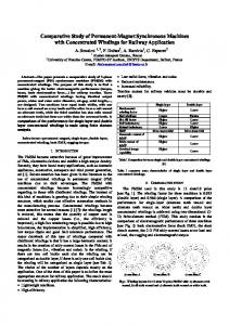
1. INTRODUCTION The world´s major energy sources are non renewable and are faced with ever increasing demand, thus are not expected to last long, these sources are mainly fossil fuels which contribute tremendously to the perennial problem of global warming. The eminent depletion and pollution problems of the above energy sources make the international community focus attention on alternative sources of energy, especially solar energy which appears to be highly promising [1]. Renewable energy, generally is classified as energy that comes from resources like sun light, wind, geothermal heat and rain that are constantly replenished. This forms of renewable energy can serve as a replacement to electricity, motor fuels, rural energy and heating [2]. Solar energy, which refers to energy from the sun, has been noted as a promising energy source as it does not produce any pollutants and is one of the cleanest source of energy. Apart from been renewable it requires low maintenance and are easy to install [3]. Photovoltaic (PV) gets its name from the process of converting light (photons) to electricity (voltage), termed the PV effect meeting only 0.1% of the total world´s energy. Recently, the development of photovoltaic has been receiving considerable attention because it promises to deliver CO2 free environment and a good alternative to the conventional fossil fuel electricity generation [4]. PV commercial production of thin-film solar cells is currently based on amorphous silicon (aSi), cadmium telluride (CdTe), and copper indium gallium selenide (CIGS), each of these has a maximum demonstrated efficiency of 12.2 %, 16.5 %, and 21.7 %, respectively [5]. The expensive rare metals in CIGS and CdTe place a great limitation to their capacity to provides world´s energy demand of 5 TW required by 2050. Lately, quaternary chalcogenide semiconductors, Cu2MIIMIV(S,Se)4 (MII=Mn, Fe, Co, Ni, Zn, Cd, and Hg; MIV=Si, Ge, and Sn), have attracted considerable interest for applications in solar cells and other optical devices due to their appropriate direct band gap and low-cost manufacturing. Solar cells with efficiencies as high as 12.6% have already been achieved using Cu2ZnSn(S,Se)4 [6] and 11.6% by using Cu2ZnSnSe4 (CZTSe) [7]. Other quaternary chalcogenides, such as Cu2Zn(Sn,Ge)Se4 and Cu2CdSnS4, have shown efficiencies up to 9.1 % and 2.7 % [8], respectively. In general, powder technologies, including also the monograin technology, are the cheapest technologies for producing materials and during the past few years there has been a rising interest for the so
7
called spheral technologies of producing solar cells. Spheral technologies are using powder materials or powder-like materials to form absorber layers [9]. Binaries or elemental precursors result to the formation of CZTSe monograin absorber material. This formation process takes place in the presence of flux material at an high temperature in an evacuated environment (quartz ampoule). The isothermal growth of Cu2ZnSnSe4 monograin powders in the presence of liquid phase of a suitable solvent material (flux) in an amount sufficient for repelling the initial crystallites leads to the formation of semiconductor materials with single-crystalline grain structure and narrow-disperse granularity [1, 6, 10]. The chemical nature of the liquid (molten) phase of used solute material impacts certain properties of the obtained absorber material [10]. The objective of this research is to study the growth process of Cu2ZnSnSe4 crystals in different molten salts (KI, NaI, CdI2, ZnI2 SnCl2 ) with the aim to understand the influence of flux material nature to the chemical composition, particle size and shape of the developed absorber materials and to find suitable flux material under defined conditions. The thesis is based on the experimental work carried out in the Laboratory of Semiconductor Materials Technology at the Department of Materials Science, Tallinn University of Technology (TUT).
8
2. LITERATURE REVIEW 2.1 Principle of solar cells Solar cells are devices through which electric charges are released from sunlight and allow them to move freely in semiconductors. This charges ultimately flow through an electric load. The physical phenomenon responsible for converting light to electricity known as the photovoltaic effect, was first observed in 1839 by a French physicist, Edmund Becquerel. He noted a voltage appeared when one of two identical electrodes in a weak conducting solution was illuminated. Today, photovoltaic systems are capable of transforming one kilowatt of solar energy on one square meter into about a hundred watts' of electricity [11]. Semiconductors are crystalline solid materials whose resistivities have values between conductors and insulators. A p-n junction is formed by placing p-type and n-type semiconductors next to one another, see Figure 2.1. The p-type, with one less electron, attracts the surplus electron from the n-type to stabilize itself. Thus the electricity is displaced and generates a flow of electrons, otherwise known as electricity. When sunlight hits the semiconductor, an electron springs up and is attracted toward the n-type semiconductor. This causes more negatives in the n-type semiconductors and more positives in the p-type, thus generating a higher flow of electricity [12, 13]. When unbound negatively charged electrons move through a crystal, electrical conduction in semiconductors can take place with a direction of current opposite to the direction of movement of the electrons. When a bound electron that should be present in the valence bond is missing, the vacancy that arises is known as a hole. Both holes and unbound electrons are known as charge carriers. Known as intrinsic semiconductors, have very few charge carriers and may hence be classified as almost insulators or very poor electrical conductors. A p-type semiconductor contains primarily holes, whereas an n-type semiconductor contains primarily free electrons. Both p and n-type semiconductors are vitally important in solid-state device technology [12]. In semiconductor materials the band below the energy gap is called the valence band, the band above the gap is the conduction band. The band gap ΔEcv, mostly denoted as Eg, is the energy separation between the highest valenceband state and the lowest conduction-band state [12]
9
Figure 2.1 Scheme of the formation of p-n junction [11].
2.1.1 Review of solar cells absorber materials The efficiency of the solar cell mainly depends on the band gap and the reflectance of the surface. Heterojunction solar cells with a wide band gap window and a narrow band gap absorber are currently becoming the focus of intensive research so as to develop efficient, stable and low-cost cells [14]. The range of ideal photovoltaic materials is limited by the matching of the bandgap of the photovoltaic material to the solar spectrum, and this lies within 1.1-1.5 eV. In addition, this type of materials must also have a high optical absorption coefficient (α > 104 cm-1), a low recombination velocity and should be able to form a good electronic junction. This range of materials encompasses silicon (Si, 1.12 eV), gallium arsenide (GaAs, 1.42 eV), cadmium telluride (CdTe, 1.49 eV) and copper indium gallium selenide (CIGS, 1-1.7 eV) which are currently the primary materials for solar cells [14, 15]. Crystalline silicon PV can be divided in cells made of polycrystalline, monocrystalline and ribbon silicon where polycrystalline plays major role followed by monocrystalline silicon [16]. Monocrystalline solar cells show the highest conversion efficiency of all silicon solar cell but the production of monocrystalline silicon wafers requires the largest investment funds. In laboratory studies, a single solar cells efficiency reaches the order of 24 %, while solar cells produced on a mass scale have efficiency around 17 %. Polycrystalline silicon solar cells are made up of large blocks of silicon. Polycrystalline are less efficient than monocrystalline, but
10
their production cost is lower due skip of energy-investment in manufacturing single crystal. Other forms of silicon thin films are the amorphous silicon solar cells (a-Si) and its alloys (aSi,Ge, a-SiC), which has achieved an efficiency of 13 % on a laboratory scale [17]. String Ribbon solar panels are also made out of polycrystalline silicon. The manufacturing of String Ribbon solar panels only uses half of the amount of silicon as monocrystalline manufacturing. This significantly contributes to lower costs, String Ribbon manufacturing is also significantly more energy extensive, which unfortunately increases the cost, commercial efficiency is around 13-14 %. In research laboratories however, the efficiency of String Ribbon solar cells have reached as high as 18.3% [18]. CdTe and CuInxGa1-x(S,Se)2 (CIGSSe) have gained 14%, 9% of PV market share since 2010, respectively. They belong to I–III–VI2 group, often simply referred to as chalcopyrite because of their crystal structure [19]. The suitability of thin-film Cu(In,Ga)(S,Se)2 solar cells usage is shown in many studies, because these chalcopyrite compounds have shown the highest efficiencies (> 19 %) for laboratory thin film solar cells. It also have a high value of absorption index which allows to use a fairly thin absorber layer in solar cells. This, in turn, significantly reduces material cost. The band gap in CIGSSe-based solar cell can be varied from 1.0 to 1.7 eV and can be reconciled with the optimal value for the Sun radiation spectrum. Depending on the production method, the following photoactive layer thicknesses are possible: (~1.5 μm) for vacuum deposition, (~2.0 μm) for co-evaporation in vacuum, (~2.0 μm) for metallic precursors handling in S/Se-vapor, (~10.0 μm) for combination of mechanochemical synthesis, wet bead milling, and screenprinting/sintering process [19, 20, 21]. The maximum efficiency of 21.7 % for CIGSSe solar cells was achieved by using the co-evaporation process [5]. Thin film solar cells based on polycrystalline cadmium telluride reached record efficiencies of 16.5 % for laboratory scale device and of 14 % for terrestrial module. CdTe has a direct band gap (Eg ≈ 1.5 eV at room temperature) and a high absorption coefficient (above 105 cm–1 at the wavelength of 700 nm). Few microns thick layer of CdTe absorbs more than 90 % of the incident light with the photon energy higher than the band gap. The maximum theoretical efficiency corresponding to such band gap is about 27 %. The small thickness required for an absorbing layer makes the cost of material for the solar cells relatively low. To date, CdTe has been deposited successfully by a variety of techniques [22]. However, despite the brightness of these thin film absorber materials, there are restriction on the usage of heavy metals such as cadmium, the limitation in supplies for indium and tellurium, and the wide fluctuation in prices of indium, gallium and tellurium. These render the combined production capacity of the existing CdTe and CIGS technologies at a small scale lower than
11
100 GW per year. This is only a small fraction of energy consumption in 2050 which is expected to be 27 TW [22]. So, these two types of solar cells can’t help for the future development in large area of TW applications [23]. To overcome these challenges, another semiconductor material with the kesterite structure, Cu2ZnSn(S,Se)4 in quaternary group I2-II-IV-VI4, could be form by replacing indium in CuIn(S,Se)2 by earth abundant and low-cost Zn and Sn [23]. Apart from this, the band gap energy of the CZTSSe ranges between Eg = 1.0–1.6 eV, which fall in the optimum band gap range. They also have high absorption coefficient (>104 cm–1), which is suitable for PV application. Therefore, more attention has been given to Cu2ZnSnS4 (CZTS), Cu2ZnSnSe4 and their solid solutions Cu2ZnSn(S,Se)4 (CZTS,Se) in recent times. Figure 2.2 below shows a schematic representative of solar cell materials.
Figure 2.2 Classification of solar cell materials [17].
2.1.2 Kesterite based solar cells Kesterite type materials Cu2ZnSnS4, Cu2ZnSnSe4 and Cu2ZnSn(S,Se)4 are attractive as absorber layer in thin film solar cells. The elements in Cu2ZnSn(S,Se)4, besides Se, are all earth abundant with a high concentration in the crust. The optoelectronic properties and potentials were first reported in Ito et al., where the growth of oriented polycrystalline CZTS films was carried out. It was reported that the crystals synthesized has a p-type conductivity with an absorption coefficient of almost 104 cm-1 and a
12
direct band gap of 1.45 eV. With all these properties, it was therefore recognized as a suitable material for thin film solar cells. The first solar cell device yielding an efficiency of 0.66 % with this type of material was reported in 1996 by Katagiri et al. using the electron beam evaporation method [24, 25]. Later, through improving technology and methodology, conversion efficiency for the kesterite solar cells have been improved every year [8, 26]. The conversion efficiency is dependent on different parameters like the growth condition, crystalline quality, p-n junction nature, carrier concentration etc. In addtion, the device efficiency is limited by formation of secondary phases in absorber layer. Although, it was found that slightly Zn rich composition of absorber layer yields better efficiencies. Another important limitation that will affect efficiency is buffer layer. Till now, the high efficient solar cells were obtained with a CdS buffer layer. ZnS buffer layer gives huge band offset whereas Zn(O,S) can be able to give good efficiencies [23, 27].
2.1.3 Crystal structure and defect studies in kesterites The compound CZTSSe could be exist in two types of crystal structures: the kesterite and stannite. The kesterite and stannite structure differ in the ordering of Cu and Zn atoms in the crystal lattice, see Figure 2.3 [26]. Kesterite has highly similar crystal structure with chalcopyrite CIGS where half of indium and (or) gallium is replaced by zinc and the other half by tin.
Kesterite
Stannite
Figure 2.3 Crystal structures of Cu2ZnSnSe4 in kesterite and stannite phases [28].
13
Crystallographic parameters for the compounds Cu2ZnSnS4 and Cu2ZnSnSe4 are given in the Table 2.1.
Table 2.1 Crystallographic lattice parameters for the compounds Cu2ZnSnS4 and Cu2ZnSnSe4 [29].
The knowledge of the defects in a semiconductor used as solar cell absorber material is of the utmost importance for efficiency improvements. Due to the presence of three cations in the quaternary system, many possible defect complexes exist. Density functional theory calculations can help to access potential defect states, and support the interpretation of experimental findings. Chalcopyrites and kesterites are doped by intrinsic defects. The dominant p-type acceptor in kesterite is the CuZn antisites and Cu vacancies [30, 31]. For highest device efficiencies, Cu-poor and Zn-rich composition ((i.e. Cu/(Zn+Sn) = 0.8-0.9 and Zn/Sn = 1.1-1.3) is required [25, 32]. It was reported that formation of the [VCu−+ZnCu+]0 pair under Znrich and Cu-poor conditions should be beneficial for maximizing solar cell performance [33].
2.1.4 Phase diagrams of Cu2ZnSnSe4 There are multitude of elements in the quaternary Cu2ZnSn(S,Se)4 compound, leading to relatively narrow single phase region and result to the formation of secondary phases, this is a great challenge in growing a single phase material. Secondary phases are very often detrimental to the solar cell performance [34]. Extremely precise composition control is not straightforward for most of the existing processing today, including evaporation, sputtering, and inkbased approaches, due to limited accuracy of deposition rate control and/or the volatile nature of the numbers of elements and precursor phases [35]. The phase diagram of Cu-Zn-Sn-S has only been studied by Olekseyuk et al. [36] which according to [37] expect to have similar phase diagram with the Cu-Sn-Zn-Se system. A further investigation of the Cu- SnSe –SnSe –ZnSe system by Dudchak et al. allowed for the determining the field of primary crystallization of the quaternary compound Cu2ZnSnSe4. Cu2ZnSnSe4 is formed according to the peritectic reaction
14
L+β ←→ Cu2ZnSnSe4 at 1061 K (β-ZnSe solid solution range) in the boundary side Cu2SnSe3 –ZnSe, which is a quasi-binary section in the Cu2Se-SnSe2–ZnSe system. In Figure 2.4, the liquidus of the polythermal Cu2ZnSnSe4 – which belong to the section (A, 50 mol.% ZnSe, 50 mol.% SnSe2) is represented by the line of primary crystallization of the β-solid solution range of ZnSe. The crystallization of the alloys in this section is completed at the temperature of a ternary peritectic process at 892 K. The polymorphous transformation (δ←→δ`) of the quaternary Cu2ZnSnSe4 compound occurs at 856 K. Hence the temperature control mechanism can be made possible during synthesis. Its homogeneity range is around 7 mol.% at the annealing temperature of 670 K [38].
Figure 2.4 Phase diagram of the Cu2ZnSnSe4-A section (A, 50 mol.% ZnSe, 50 mol.% SnSe2): (1) L, (2) L +β, (3) δ, (4) β+ δ, (5) δ+δ`, (6) δ`, (7) β+ δ`, (8) L+ β +δ, (9) β + γ + δ, (10) L+ β + γ, (11) β + γ, (12) β + γ + δ. L – liquid phase, β – ZnSe, γ – SnSe2, δ(δ`) - Cu2ZnSnSe4 [38].
15
Due to the complexity of the quaternary material system, several binary and ternary sulfides (or selenides) including Zn(S,Se), Cux(S,Se), Sn(S,Se)x, and CuxSn(S,Se)y phases can easily form during the absorber film fabrication which may adversely affect the photovoltaic performance of the resulting device. The ternary phase diagram of the Cu2S-ZnS-SnS2 (or Cu2Se-ZnSeSnSe2) system exhibits very narrow region of stability for single phase kesterite CZTS/CZTSe crystals [37]. To regulate the formation of this unwanted phases, isothermal phases section of CuSe–ZnSe–SnSe system as shown in Figure 2.5 have been studied in [38].
Figure 2.5 Isothermal section of the Cu2Se–ZnSe–SnSe2 system at 670 K [38].
The isothermal section of the quasi-ternary Cu2Se–ZnSe–SnSe2 system at 670 K consists of the homogeneity ranges of the α-, β-, δ- and γ -solid solutions of Cu2Se, ZnSe, SnSe2 and the lowtemperature modification of the quaternary compound CuZnSnSe4 [38].
2.1.5 Review of Cu2ZnSnSe4 thin film fabrication Several fabrication routes have been investigated for the preparation of CZTSSe thin-films since the first working photovoltaic cell reported by Katagiri et al. in 1997 [39]. In studies [39, 40, 41, 42, 43] were reported the fabrication of CZTSe by vacuum based evaporation and sputtering techniques. All the sputtering processes share some similarities the most of which is the use of physical process such as laser ablation or the use of energetic particles to remove material from a target material and deposit in a vapor state of a substrate. In contrast to chemical
16
vapour deposition, the precursor gas containing the element to be deposited is reacted in the chamber and deposited unto the substrate [44]. Non-vacuum approaches using nanoparticle inks is another promising approach. The advantage of this technique is that it can be easily adapted for large-scale manufacturing, this method basically involves ink formulation, inkjet printing and annealing [43, 45]. Other notable methods include hydrazine-based solution-particle slurry, electrodeposition and spray pyrolysis [42]. However, use of highly toxic and hazardous hydrazine severely limits the scalability of this process for high volume commercial production. Wibowo et al. [46] showed straightforward technique for the synthesis of the single phase Cu2ZnSnSe4 powders using a solid state reaction from elemental Cu, Zn, Sn and Se powders at 500°C in a quartz tube furnace under an Ar flow at atmospheric pressure. Other non-vacuum thin-film fabrication approaches promise cost reduction, however the reproducibility and film quality is compromised [39]. Leinemann et al. reported the formation of CZTSe in potassium iodide as flux from binary precursors [47]. Powder technologies are one of the cheapest technologies for materials production and it is shown that the synthesis of CZTSe from initial binary compounds in the isothermal re-crystallization in different molten fluxes appears to be a relatively simple, inexpensive and convenient method to produce powder materials with very good crystal structure, homogeneity, and reduced concentration of inherent defects [48].
2.2 Monograin powder technology 2.2.1 Overview The technologies used today for manufacturing solar cells are wafers and the thin film technologies. This unfortunately is a very expensive process not only in terms of money but also in terms of energy input. In monograin solar cells however, solar cell powders replaces monocrystalline wafers or thin films which allows for cheaper and more efficient material production and material loss [49]. The main feature of monograin layer (MGL) technology is that fabrication of absorber/junction formation and cell/module formation is separated, which leads to the several benefits in both stages of MGL production. High temperatures are allowed in absorber material production, and the possibility of using cheap, flexible, low temperature substrates allows production of cheap flexible solar cells [9].
2.2.2 Monograin powder growth The formation of monograin powders by the isothermal recrystallization of initial powders in different fluxes have been reported in [9, 49, 50, 48, 47]. This process results the formation of
17
homogeneous semiconductor materials with single-crystalline grains which are physically perfect, uniformly distributed doping impurities and narrow granulometric composition. The one way process makes it possible to form a lot of little perfect single crystals instead of one traditional big one [50]. The driving force in this growth process is the difference in surface energies of crystals of unequal sizes. The quaternary compounds can be formed from different precursors: from the constituent elements, from binary chalcogenides and from elemental metal alloys and chalcogen [51]. The growth of single crystalline powder grains takes place at temperatures higher than the melting point of the used flux material [52]. Therefore, the synthesis of CZTSSe monograin materials has been proceeded starting from binary compounds that have high melting temperatures and the main synthesis reaction occurs at temperatures higher than the melting point of flux (KI). This avoids the sintering of precursor particles before the synthesis of CZTSSe starts. The liquid phase of a flux material is also advantageous for the synthesis of multi-component compounds, allowing fast diffusion of constituent elements through liquid phase and providing therefore uniform composition of absorber materials for solar cells [53]. However, due to the complexity in the synthesis of CZTSe monograins, the formation of binary and ternary phases is a common feature. A very good control over the synthesis parameters is required not only to obtain the desired phase, but also to have a tight control over the stoichiometry of the materials [54]. According to the study in report [55], the best synthesis temperature for producing a single phase kesterite crystal in molten flux is 750ºC. Several reports [9, 47, 48] also established the successful synthesis of Cu2SnZnSe4 at 740ºC, the synthesis duration varies from 90 hours to one week. All monograin powders exhibited p-type conductivity with resistance increasing from 0.4Ω to 230Ω with decreasing the ratio of Cu/(Zn+Sn) and increasing ratio of Zn/Sn [48].
2.2.3 Formation of Cu2ZnSnSe4 There are successive reactions taking place in the bulk of the layer between the elements leading to binaries, ternaries and finally the quaternary compounds [56]. It was found that between 200 and 450°C, metal-chalcogenide binaries such as CuSe, Cu2Se, and SnSe form. At around 380°C, the phase decomposition of γ-CuSe to β-Cu2Se takes place which then react with liquid Se and SnSe, forming cubic Cu2SnSe3 phase. As the disappearance of ZnSe phase at 350°C and the ternary phase Cu2SnSe3 at 400°C occurs, it is most probable that at around 400-700°C Cu2SnZnSe4 is already the dominant phase. The main reaction baths for Cu2SnZnSe4 formation are outlined below as Eqs. 2.1-2.4 [57].
18
γ-CuSe + Se (Liquid)
(2.1)
β- Cu2Se + Se (Liquid)
(2.2)
300-320°C:
CuSe2
380°C
2γ-CuSe
380°C
β-Cu2Se + Se (Liquid) + SnSe
400-700°C
Cu2SnSe3 +ZnSe
Cu2SnSe3 Cu2ZnSnSe4
(2.3) (2.4)
It was shown [48] that single phase CZTSe monograin powder could be synthesized from a precursor mixture comprising metal ratios of Cu/(Zn + Sn) = 0.92−0.95 and Zn/Sn = 1.0−1.03. A reasonably long time is needful to allow complete reaction of all binaries and formation of large monograins. For one-step process however, Cu-rich growth conditions are needed at the beginning of the reaction in order to foster growth of large grains. Unfortunately, unlike the CIGS counterpart, the elements involved in CZTSe evaporates and sublimes easily. Zn at 430°C, SnSe at 350°C and Sn evaporates at 460°C [56]. Following the report in [49], it was stated that higher temperature leads to the decomposition of CZTSe according to the Eq. 2.5: Cu2ZnSnSe4(s) ←→ Cu2Se(s) + ZnSe(s) + SnSe(g) + Se(g)
(2.5)
If the equilibrium of this reaction goes to the right direction, ZnSe, SnSe and Se formation and losses will occur, leading to a Cu2Se-rich layer, increasing number of shunts in layer and preventing good photovoltaic efficiencies [56]. It becomes highly needful to control the synthesis environment and optimize other synthesis conditions.
2.2.4 Flux materials Generally they consist of oppositely charged species, but the character of these species varies from classical ions in the typical molten salts to charged polyatomic molecules in ionic liquids. The prototype of molten salts are fused alkali halides that contain closed-shell alkali and halogen ions [58]. The liquid phase of a flux is an advantage for the synthesis of multicomponent compounds because it allows fast diffusion of constituent elements through liquid phase and providing therefore uniform composition of absorber materials for solar cells. Suitable flux material should have low melting temperature, low vapor pressure and high solubility in water, allowing an easy separation of the powder particles from the flux [53]. Several flux materials such as KI, CdI2, NaI have been used for studies and their results published accordingly [63, 59, 60]. Other flux materials such as ZnI2 and SnCl2 seems to be promising flux materials as they demonstrate inherent chemical properties with the existing flux salts.
19
Cadmium iodide has an hexagonal shape which is considered to be consisting of two layers of hexagonal closed pack iodine ion nested between them [61]. More than 250 polytypes of cadmium iodide have been observed so far and crystal structure of nearly 190 polytypes have been worked out. The CdI2 structure consists of different stackings of CdI2 sandwiches in each of which a layer of cadmium ions is sandwiched between two close packed layers of iodine ions. [62, 64, 65]. Sodium iodide is a compound with about 30ºC lower melting temperature than KI, allowing to reduce the synthesis temperature. Its chemical behavior is close to KI and the non-toxicity is an advantage comparing with CdI2. It is very important to have dehydrated NaI, due to its trend to form NaI x 2H2O. After heating under continuous vacuum pumping for 4 h up to 370ºC there was no water emission detected by mass spectrometry (MS) [53]. The only study about the synthesis of CZTSe in molten NaI as flux was carried out in Leinemann et al. where it was concluded that in the presence of solid NaI the formation of CZTSe is inhibited. Up till the period of this study, there has been no experiment regarding to the formation of CZTSe in SnCl2 and ZnI2. SnC12 is a white crystalline solid. SnC12 can be prepared by heating Sn in a flow of gaseous HC1 with a calculated density of 3.91g/cm3. It is obtained as a fine crystalline powder. The crystals are very sensitive to atmospheric influence. SnCl2 has a lone pair of electrons, such that the molecule in the gas phase is bent. In the solid state, crystalline SnCl2 forms chains linked via chloride bridges as shown in Figure 2.6 [65]. The dihydrate is also three-coordinate, with one water coordinated on to the tin, and a second water coordinated to the first. The main part of the molecule stacks into double layers in the crystal lattice, with the "second" water sandwiched between the layers. The solubility in water is 83.9 g/100 ml (0°C) while its melting temperature is 247°C for anhydrous and 37.7°C dihydrate SnCl2. SnCl2 has coordination geometry of trigonal pyramidal (anhydrous) [66].
Figure 2.6. Structure of crystalline SnCl2 [66].
20
2.2.5 Chemical interactions between Cu2ZnSnSe4 and flux materials Several studies, [52, 53, 58 59, 60, 67] has reported the synthesis of CZTSe monograin powders in potassium iodide flux. Potassium iodide has high melting temperature (686ºC) and due to this, rather high contamination of synthesized absorber material with potassium and iodine is predicted. Such Cu2ZnSnSe4 monograin powder crystals grown in molten KI had tetragonal shape with rounded grain edges [58]. One prerequisite for monograin growth is that the amount of the components for the CZTSe synthesis and the amount of flux must be nearly equal to provide enough volume of the liquid phase for filling the free volume between the solid particles. The formation process of CZTSe begins after the melting of the flux material [48]. The solubility of CZTSe binary precursors and the preceding reaction enthalpies were studied in [47]. The solubility of precursor compounds in KI is low: 0.086 mole % for ZnSe, 0.27 mole % for SnSe, 3.6 mole % for Cu2Se. On the basis of Raman analyses of the sample heated at 400ºC, the formation of Cu2SnSe3 and CZTSe were found. Following the experiment conducted in [59], conclusions were made, that the main formation process of CZTSe happens close to the melting point of KI, while Raman, XRD and DTA showed the formation of various ternaries and binaries phases before. Also the melting temperature of the eutectic mixture of the SnSe/SnSe2 system was seen in the DTA curve of KI/SnSe as an endothermic peak at 626ºC. So far, KI as a flux material has proven to be a good flux material if the synthesis conditions can be optimized [59,47]. The solubility of Cu2ZnSnSe4 in KI was 0.61 mole %. The doping concentration of K in CZTSe is determined by ICP-MS to be 215 μg/g. XRD analysis showed, that the formation of CZTSe in KI involves several steps. In samples, heated at 250 °C, some Cu1.85Se was found, but at 400°C, SnSe2 was detected. At 520 °C, Cu2SnSe3 was found. At 680°C (a little below the melting point of KI), Cu2ZnSnSe4 was formed [59]. The possible chemical reactions between the binary precursor compounds CuSe, SnSe, ZnSe in molten CdI2 as flux materials was carried at melting temperature 390ºC (much lower than the melting point of KI). In samples heated at 370ºC Cu2CdSnSe4, SnSe2 and ZnSe were found. At 400ºC Cu1.8Se, Cu2SnSe3 and SnSe prevailed. At 590ºC Cd0.22Zn0.78Se, CuI and Cu2ZnSnSe4 existed. At 740oC beside Cu2ZnSnSe4 also CuSe and Cu4Se3 were detected, the presence of solid solution ZnxCd1xSe
and the formation of pentanary Cu2(ZnxCd1-x)SnSe4 was observed. It was therefore
concluded that the formation of multiphase products makes the usage of CdI2 as a solvent for synthesis of single phase monograin powders of CZTSe complicated [58].
21
2.2.6 Monograin layer solar cells The idea of monograin layers (MGL) for construction of optoelectronic devices was proposed more than 30 years ago by researchers of the Philips Company. A good MGLs combine the high photoelectronic parameters of monocrystals [68]. The MGL consists of a one-crystal-thick layer of grains of the monograin powder embedded in an organic resin [69]. Mellikov et al. reported the fabrication of monograin layer solar cells (graphite/CZTSSe/CdS/ZnO) which were made from powder grains with diameters of 56-63µm. Powder crystals were covered with chemically deposited CdS buffer layer. For the MGL formation, a monolayer of CZTSSe powder crystals were poured onto a thin layer of epoxy. After polymerization of this epoxy, iZnO and ZnO:Al were deposited by RF sputtering onto the open surface of the layer. The structures were completed by vacuum evaporation of 1-2 µm thick In-grid contacts onto the ZnO window layer. The structures were glued onto a glass substrate. The back contact areas of crystals that were originally inside the epoxy were opened by etching the epoxy with H 2SO4 and by additional abrasive treatment. Back contacts were made using graphite paste and the solar cell structure was ready (Figure 2.7).
Figure 2.7 Schematic illustration of the standard structure of monograin layer solar cell [70]. The photovoltaic properties of this structure are very promising. During the last years TUT group have reached the record parameters of Cu2ZnSnS4 monograin layer solar cell as follows: the open-circuit voltage (Voc) = 743 mV, short-circuit current (jsc) = 26 mA/cm2, fill-factor
22
(FF)=69 % and conversion efficiency (η) = 9.38 %. The short-circuit current has its maximum value at the room temperature and then decreases with the lowering temperature. Monograin layer technology combines advantages from two techniques – the monocrystalline nature of the material and the greater freedom in the choice of dimensions and electrical parameters of the thin film technology. The main feature of monograin layer technology is that fabrication of absorber/junction formation and cell/module formation is separated, which leads to the several benefits in both stages of MGL solar cell production. In spite of their advantages, until now MGL-s have not found wide use in the industrial production of photoelectronic devices and solar cells. This could be explained by some unsolved technical problems which include many designs need powder grains of nearly equal size and perfect monocrystalline structure [68, 69, 70].
2.3 Analytical methods 2.3.1 Scanning electron microscope Scanning electron microscope (SEM) is one of the most versatile instruments available for the analysis and examination of the microstructure morphology characterizations [71]. The specimen is bombarded by a convergent electron beam, which is scanned across the surface. This electron beam generates a number of different types of signals, which are emitted from the area of the specimen where the electron beam is impinging. The induced signals are detected and the intensity of one of the signals (at a time) is amplified and used to as the intensity of a pixel on the image on the computer screen. The electron beam then moves to next position on the sample and the detected intensity gives the intensity in the second pixel and so on [72]. Micrograph of a Cu2ZnSnSe4 crystal as analyzed by a scanning electron microscope is shown in Figure 2.8.
23
Figure 2.8 SEM micrograph, showing the shape and morphology of Cu2ZnSnSe4 crystals.
2.3.2 Energy dispersive X-ray spectroscopy Energy dispersive X-ray spectroscopy (EDX, EDX or XEDS) is a qualitative and quantitative X-ray micro analytical technique that can provide information on the chemical composition of a sample for elements with atomic number. The X-rays are detected by an energy dispersive detector which displays the signal as a spectrum, or histogram of intensity (number of X-rays or X-ray count rate) versus X-ray energy. The energies of the characteristic X-rays allow the elements making up the sample to be identified, while the intensities of the characteristic X-ray peaks allow the concentrations of the elements to be quantified. The underlying principles for generation of X-rays and detection by EDX are the same for SEM [73].
2.3.3 Raman spectroscopy Raman spectroscopy is a totally non-invasive, label-free technique which excites vibrations of molecular bonds [71]. When light interacts with matter, the photons, which make up the light, may be absorbed or scattered, or may not interact with the material and may pass straight through it. If the energy of an incident photon corresponds to the energy gap between the ground state of a molecule and an excited state, the photon may be absorbed and the molecule promoted to the higher energy excited state. The scattered photons can be observed by collecting light at an angle to the incident light beam. However, the main scattering technique used for molecular identification is Raman scattering [71]. The main Raman modes for the Cu2ZnSnSe4 phase are
24
two main peaks at 173 cm-1 and 196 cm-1 and third less intensive peak at 233 cm-1 according to [67].
2.3.4 Sieving analysis Sieving analysis method allows to determine the percentage of different grain sizes contained within a synthesized powder. In monograin powder technology, certain narrow granulometric fractions of grown powders (between 38 µm to 125 µm) are useful for the formation of the absorber layer in the MGL solar cell structure [9]. The monograin growth process is either slow or high depending on the solubility in the flux material. If the particle size distribution follows a log-normal distribution in which the distribution shifts with growth duration t, it allows the use of the median particle size dm to describe the grain growth according to the Equation 2.6. dm = At1/n Exp (-Ed/KT)
(2.6)
where A is a constant for a given flux and compound, k is the Boltzmann constant, T is the growth temperature, Ed is the activation energy of linear crystal growth and n is the geometric factor of growth mechanism [74].
2.4 Summary of literature overview and the objective of the study The sun is a promising source of renewable energy with unlimited capacity to deliver a clean energy to mankind. Currently the PV market is dominated by silicon wafers which has been recognized to be expensive. Thin film on the other hand with a reasonable conversion efficiency and optical properties cannot meet the required energy demand as reserve of indium, gallium and tellurium are very limited and expensive. Kesterites Cu2ZnSn(S,Se)4 are attractive materials for absorbers in thin film solar cells as they based on abundant, cheap and non-toxic elements. Monograin powder technology is cheap non-vacuum method for the formation of homogeneous semiconductor materials with single-crystalline grain structure, uniformly distributed doping impurities and narrow-disperse granularity. The separation of the fabrication of absorber/junction and cell/module formation leads to the several benefits: high temperatures are allowed in absorber material production, and the possibility of using cheap, flexible, low temperature substrate for production of solar cells. Elemental or binary precursors can be used in synthesizing monograin powders and in both case multitude of elements in the quaternary Cu2ZnSn(S,Se)4 compound are formed, leading to relatively narrow single phase region and result to the formation of secondary phases which are very often detrimental to the solar cell performance.
25
The liquid phase of a flux material is an advantage for the synthesis of monograin powders as it allows fast diffusion of constituent elements through liquid phase and providing therefore uniform composition of absorber materials for solar cells. Several flux materials such as KI, CdI2, NaI has been used for studies while others such as ZnI2 and SnCl2 has not been studied as of now. ZnI2 and SnCl2 promises to be a good flux materials because they also possess inherent properties like the existing flux materials: low melting temperature, low vapor pressure and high solubility in water, allowing an easy separation of the powder particles from the flux. In the isothermal growth of Cu2ZnSnSe4 (CZTSe) monograin powders the chemical nature of the liquid (molten) phase of used solute material impacts certain properties of the obtained absorber material. Therefore, it becomes highly needful to select a suitable flux material for the synthesis of monograin powders. The objective of this research is to study the growth process of Cu2ZnSnSe4 crystals in different molten salts (KI, NaI, ZnI2, CdI2, SnCl2) with the aim to understand the influence of flux material nature to the chemical composition, particle size distribution, shape and surface morphology of the crystals of the developed absorber materials and to find suitable flux material under defined conditions.
26
3.
EXPERIMENTAL
In this study binary precursor materials CuSe, ZnSe, SnSe and elemental selenium with 2N purity were used to synthesize Cu2ZnSnSe4 monograin powders in the liquid phase of the different flux materials. The synthesis processes of Cu2ZnSnSe4 monograin powders were performed in an evacuated quartz ampoules at 700°C for KI, CdI2, NaI and for ZnI2 and SnCl2 at 500ºC for 110 hours.
3.1 Degassing process of flux materials The flux materials used for this experiment were thoroughly degassed for dehydration by heating under continuous vacuum pumping. The aim of degassing was to get rid of adsorbed gasses and bonded crystal water. The heating agitate the system which in turn convert every form impurity into vapor and subsequently, the gas phase is removed from the ampoule. SnCl2, CdI2 were degassed at 150ºC, NaI, KI and ZnI2 were degassed at 250°C.
3.2 Preparation of monograin powders Binary compounds CuSe0.978, SnSe, ZnSe and elemental Se were used as precursors for an intended kesterite composition of Cu1.85Zn1.1SnSe4.1 and 3.8 % mole excess of selenium stoichiometric ratios. ZnSe and elemental Se were obtained commercially, while CuSe and SnSe were synthesized in TUT laboratory by weighing 1:1 ratio of the constituent elements (copper wire, tin strip and selenium pellet) and subjected to furnace annealing in a closed quartz ampoules at 560°C for CuSe and at 700ºC for SnSe. In CuSe the unreacted selenium was removed by degassing the system at 260ºC for 6 hours. The binaries obtained had a chemical ratio of CuSe0.978 and SnSe. For the use of elemental selenium, the Se pellets were grinded into a fine powder in an agate mortar. The precursor materials were mixed and grinded inside the ball mill for 15 minutes at a rotational speed of 450 rev/min (see Figure 3.1 f and c) and divided into five different portions. An amount of different flux material which was nearly equal to the amount of component for the kesterite material (Vprecousors : Vflux = 1:1.14) was added to the precursor. This is important in monograin powder technology to provide enough volume of the liquid phase for filling the free volume between the solid particles. This mixture was further milled mechanically to enhance homogeneity. Each mixture was transferred into different quartz ampoule saturated with Ar gas, degassed under dynamic vacuum for overnight after which they were all evacuated and sealed. Altogether, 3 different powders were annealed for 110 hours at 700°C except for
27
the synthesis involving SnCl2 and ZnI2. The annealing process for experiments included SnCl2 and ZnI2 as flux materials were carried out at 500ºC. The experiment involving SnCl2 and NaI were performed inside a glove box saturated with Nitrogen gas in order to avoid contamination with oxygen and moisture (see Figure 3.1 a) because these two flux materials are highly hygroscopic. The synthesis growth of monograin powders in different molten salts were carried out twice: (1) In the first experiment, the precursor materials (CuSe, SnSe, ZnSe) were milled separately before mixing with the flux materials. Mechanically milled binaries and unmilled flux materials were mixed manually and sealed into evacuated quartz ampoules. (2) In the second experiment, the binaries (CuSe, SnSe, ZnSe) and the flux material were mixed together by using ball milling. The annealing was done in a furnace chamber. It took approximately five hours for the furnace with the sample inside to heat up to the required temperature. The growth was stopped by quenching the synthesis ampoules to room temperature after the synthesis duration was reached (see Figure 3.1 b). The flux material was removed from the system by a leaching process by washing the samples with distilled water and thoroughly rinsed in an ultrasonic bath to enhance agitation. The ultrasonic bath water was heated up to 50°C to increase the flux material solubility speed in washing water. This process was repeated several times until a completely clear washing water was obtainable indicating that all the flux material has been completely removed. The released monograin powder was dried oven night in a hot-air thermostat at 56°C. In the case of CdI2, it took longer time to remove completely the flux material from solid particles comparing to other experiments.
28
Figure 3.1 Experimental steps of the monograin powder preparation process: (a) glove box saturated with Nitrogen gas, (b) the precursors were milled mechanically to ensure homogeneous mixture, (c) the ball milling system, (d) annealed samples with different flux materials showing their different colors and appearances, (e) the sieving machine containing different size of sieves (ranging from 38µm-125 µm), (f) monograin fractions obtained from different sieves after sieving.
29
3.3 Characterization of monograins In this study, the particle size distribution was determined by sieving analysis. Granulometric fractions of the synthesized powder ranging from 38 μm to 125 μm was obtained by sieving the monograin powders on the sieving machine followed by a manual sieving. The sieves used are separated into the following fractions: 38-45, 45-56, 56-63, 63-75, 75-80, 80-90, 90-100, 100112 and 112-125 µm (See Figure 3.1 e and f). The morphology was investigated by scanning electron microscopy (SEM). High resolution scanning electron microscope Zeiss HR SEM Ultra 55. Energy dispersive X-ray spectroscopy was used to determine the elemental composition of the synthesized monograin powders. Raman data was collected on a Horiba`s LabRam 800 HR (High Resolution) spectrometer equipped with a multichannel CCD (Charge Coupled Device) detection system in backscattering configuration with an Olympus microscope module. The laser light used in the experiment was a green light with a wavelength of 532 nm with an intensity of 100 mW. The integration time used for the measurement was 150 s for the quaternary sample. The sample was studied within a spot of 10 μm in diameter.
30
4. RESULTS AND DISSCUSION 4.1 The yield of material Mass losses in the experiment were estimated for different flux materials. Materials losses were also in pre-synthesis preparation processes, like ball milling process and transferring of materials from the bigger degassing ampoule into smaller synthesis quartz ampoules. Basic material loss was emerged during the synthesis and recrystallization, washing and sieving process. All these losses are collated and presented in Table 4.1. Table 4.1 Experimental material loss and yield for Cu2ZnSnSe4 monograin powder grown in different molten salts obtained in the two experiments. FIRST EXPERIMENT Flux system
Yield percent of
Loss percent of material (%)
Cu2ZnSnSe4 powder (%) NaI
55.46
44.53
SnCl2
53.72
46.27
CdI2
97.88
2.1
SECOND EXPERIMENT Flux system
Yield percent of
Loss percent of material (%)
Cu2ZnSnSe4 powder (%) KI
82.744
17.0
NaI
83.27
19.19
CdI2
98.04
1.96
The result above indicates that many materials were lost in the first experiment corresponding to a relatively low yield of quaternary compound. The second experiment reduced materials loss maximally as seen in the data above. Indicating that the second method is a preferable method to curb materials loss. Mechanical milling improves the homogeneity of the mixture of binaries (CuSe, SnSe, ZnSe) and the flux material. CdI2 flux system has the highest material
31
yield. Most of the material loss can be attributed to loss during washing, several tiny particles were washed away during the process. Higher yield of quaternary compound in cadmium iodide can attributed to its higher solubility value enhancing the growth process compared to others, quite large particles were formed and almost all were retained during the process. Additionally, in the case of CdI2, Zn atom replaces Cd in quaternary compounds thereby forming solid solution of Cu2(Zn,Cd)SnSe4, consequently, as the Cd atom are heavier, material mass increases resulting to higher percentage yield. Lastly, the material obtained with ZnI2 is higher than the input (approximately 28 % more). The hygroscopic nature of ZnI2 and the inability to completely remove the moisture and oxygen makes it vulnerable to chemical reaction during synthesis and washing process resulting into the formation of large amount of amorphous substance.
4.2 Particle size distribution Sieving analysis helps to estimate the particle size distribution of the monograins by evaluating their linear growth. Particle size fractions lower than 38 µm and greater than 125 µm are left out while other fractions are taken as 100%. In the Figures 4.1-4.6 the mass per unitary amount of each fractions of the monograins grown in different molten salts are presented (in the case of first and second experiment). Granulometric fractions of monograin powders should follow the normal (Gaussian) distribution according to the Equation 4.1 [74, 75]
(4.1) The parameter x̄ is the mean or expectation of the distribution (and also its median and mode). The parameter σ is its standard deviation; its variance is therefore σ2. When the particle size distribution follows the log-normal distribution, it allows the use of median particle size dm to describe the monograin growth mechanism.
32
KI FLUX 0,25
Mass/Unit
0,20
0,15
0,10
0,05
0,00 38-45
45-56
56-63
63-75
75-80
80-90
90-100 100-112 112-125
Fractions (µm)
Figure 4.1 Sieving analysis graph of particle size distribution for CZTSe monograin powder synthesized in molten salt of KI (first experiment).
NaI FLUX 0,16 0,14
Mass/Unit
0,12 0,10 0,08 0,06 0,04 0,02 0,00 38-45
45-56
56-63
63-75
75-80
80-90
90-100 100-112 112-125
Fractions (µm)
Figure 4.2 Sieving analysis graph of particle size distribution for CZTSe monograin powder synthesized in molten salt of NaI (first experiment).
33
SnCl2 FLUX
0,25
Mass/Unit
0,20
0,15
0,10
0,05
0,00 38-45
45-56
56-63
63-75
75-80
80-90
90-100 100-112 112-125
Fractions
Figure 4.3 Sieving analysis graph of particle size distribution for CZTSe monograin powder synthesized in molten salt of SnCl2 (first experiment). Figures 4.1-4.3 are showing a slight deviation from the log-normal distribution curve with a little exception to NaI flux material which tend to slightly fit in. The indication of this is that the first experimental procedure is not a suitable method for obtaining a good particle size distribution for during powder growth. In the second experiment, all the graphs (Figures 4.44.6) conform to the log-normal distribution. The best shape of presented graphs was observed for CdI2 with highest amount of grain sizes in the fraction range of 75-80 µm. Monograin powder synthesis growth in ZnI2 was left out because all the monograin powder obtained on sieving had smaller size than 38 µm. The hygroscopic nature of ZnI2 hindered the growth process, the presence of oxygen and moisture imposes very high vapour pressure on the synthesis ampoule almost making the ampoule to break, consequently, the tempereature has to be kept low to prevent this. The hygroscopicity of ZnI2 contributed largely to the poor growth pattern and this suggest that ZnI2 is not a suitable flux material for monograin synthesis because apart from the fact that it doesn’t produce usable fractions applicable to solar cells. The technology for the drying process might be too costly and require extra effort. This is a disadvantage to sustainability and energy saving.
34
0,25
Sieve Analysis for CZTSe synthesized in NaI
Mass/Unit
0,20
0,15
0,10
0,05
0,00 38-45
45-56
56-63
63-75
75-80 80-90
90-100 100-112 112-125
Fractions (µm)
Figure 4.4 Sieving analysis graph of particle size distribution for CZTSe monograin powder synthesized in molten salt of NaI (second experiment).
Sieve analysis for CZTSe synthesized in KI flux 0,25
Mass/Unit
0,20
0,15
0,10
0,05
0,00 38-45
45-56
56-63
63-75
75-80
80-90
90-100 100-112 112-125
Fractions (µm)
Figure 4.5 Sieving analysis graph of particle size distribution for CZTSe monograin powder synthesized in molten salt of KI (second experiment).
35
Sieve analysis for CZTSe synthesized in CdI2
0,30
0,25
Mass/Unit
0,20
0,15
0,10
0,05
0,00 38-45
45-56
56-63
63-75
75-80
80-90
90-100
100-112 112-125
Fractions (µm)
Figure 4.6 Sieving analysis graph of particle size distribution for CZTSe monograin powder synthesized in molten salt of Cdl2 (second experiment). Figure 4.7 and 4.8 below shows the particle size distribution of monograin powder grown in different molten salts for both experiment obtained from the results of the sieve analysis. The black solid horizontal line marks (50%), it shows the powder median grain size values calculated from weight percent. All experimental lines drawn below this solid horizontal line indicate the formation of small fractions. The first experiment doesn’t comply to the log–normal distribution, the second experiment however (Fig 4.7) doesn’t show total compliance with exception to the synthesis done with cadmium iodide where two different sets of parallel lines conforming with the result obtained in 4.6. This kind of behaviour indicates to the different mechanisms in the crystal growth process. The first line which correspond to single crystal growth was observed in the range of 38-75 μm while the second part of the line was observed in the range of 80-112 μm. It could be infered that this set of grains are sintered and the sintering effect produced this nature of graph. Also, the SEM analysis revealed large sintered grains obatined during the sysnthesis growth of CZTSe in CdI2. The median grain size gathered from the flux material versus median particle size dependence graph (Fig. 4.7, 4.8) were for KI 52 μm, CdI2 70 μm, SnCl2 52 μm and for NaI 73 μm (first experiment), 65 μm (second experiment).
36
Weight percent less than stated size (%)
Particle size distribution KI NaI SnCl2
99,5
95
70
40
10
1 40
60
80
100
120
Particle size (m)
Figure 4.7 Particle size distribution of Cu2ZnSnSe4 monograin powders synthesized in KI, NaI and SnCl2 (first experiment).
Weight percent less than stated size (%)
Particle size distriubution
99,5
NaI KI CdI2
95
70 40
10
1 20
40
60
80
100
120
Particle Size (µm)
Figure 4.8 Particle size distribution of Cu2ZnSnSe4 monograin powders synthesized in KI, NaI and Cdl2 (second experiment).
37
4.3 Elemental composition of Cu2ZnSnSe4 monograin powders In Figure 4.9, the compositional ratios of all the CZTSe elements synthesized in different fluxes for both experiments were presented. The bulk composition of the synthesized monograin powders was determined from polished cross-sectional samples using EDX analysis. There are differences between the input composition (Cu1.85Zn1.1SnSe4.1) and the obtained composition for the Cu2ZnSnSe4 synthesized in different molten salts. However, the deviation varies from one flux material to another. A copper poor and a zinc rich composition was obtained for NaI, KI and ZnI2 flux materials while tin composition shows a little deviation. For SnCl2, a zinc poor composition was obtained which could be attributed to Sn atoms replacing the Zn in the quaternary compound. According to [21], such composition is not ideal for making a good solar cell. In the second experiment (see Figure 4.10), almost all the monograin powders have similar chemical composition with the input, a zinc rich composition is additionally obtained which has been established to be good for solar cell perfomance [42]. In the case of using CdI2 the concentration ratio of Cu/Sn increased.
Chemical Composition 2,0
Compostional ratios
1,8
Cu\Zn+Sn Zn\Sn Cu\Sn Se/Met
1,6
1,4
1,2
1,0
0,8
Input
KI
NaI
SnCl2
CdI2
ZnI2
Flux material
Figure 4.9 The concentration ratios of Cu/(Zn+Sn), Zn/Sn, Cu/Sn and Se/Met of monograin powders synthesized in different molten salts (first experiment).
38
Chemical Composition 2,0
Composotional ratio
1,8
Cu\Zn+Sn Zn\Sn Cu\Sn Se/Met
1,6 1,4 1,2 1,0 0,8
Input
NaI
KI
CdI2
Flux Materials
Figure 4.10 The concentration ratios of Cu/(Zn+Sn), Zn/Sn, Cu/Sn and Se/Met of monograin powders synthesized in different molten salts (second experiment).
4.4 Phase composition of Cu2ZnSnSe4 monograin powders Raman spectroscopy was performed on all the flux materials used in the experiment (Results shown in Figure 4.11-4.15). A strong sharp peak was observed at 120 cm-1 in see Figure 4.11 which correspond to pure ZnI2 as jusitified in [75] also, a stong sharp peak was noted in Figure 4.12 at 109 cm-1 corresponding to pure CdI2 in agreement with [77]. In NaI Raman spectra (see Figure 4.13), the spectrum is roughly divided into two regions of nearly equal width with lines grouped in each region. The first region contain notable peaks at 90, 114, 135, 149 cm-1 while the second region contain peaks at 281, 354 and 418 cm-1. The bands in the second area are combinational of the first region modes with the inactive first order and the active second order modes matching the NaI Raman peaks reported in [78]. This measurement was done to determine whether unwashed flux materials could be detected in the monograin powders by Raman spectroscopy.
39
ZnI2 Flux
Normalized Intensity (arb units)
700
120
600 500 400 300 200 100
76 69
0 60
70
80
90
100
110
120
130
140
150
160
-1
Raman shift (cm )
Figure 4.11 Raman spectra of ZnI2. CdI2 Flux 800
109 CdI2
Normalized intensity (arb units)
700 600 500 400 300 200 100 0 80
90
100
110
120
130
140
-1
Raman Shift (cm )
Figure 4.12 Raman spectra of CdI2.
40
150
160
NaI flux 114
Normalized intensity (arb. units)
25
354
20
135 149
15
281 418
90 73
10
5
0 50
100
150
200
250
300
350
400
-1
Raman Shift (cm )
Figure 4.13 Raman spectra of NaI. SnCl2 Flux 159
Normalized Intensity (arb units)
500
190 400
93
300
200
100
0
80
100
120
140
160
180
-1
200
220
Raman shift (cm )
Figure 4.14 Raman spectra of SnCl2.
41
240
450
Raman spectra for KI flux 26 24 22
Intensity (arb. units)
20
KI 93
KI 170
KI 209
18 16 14 12 10 8 6 4 2 0 50
100
150
200
250
300
350
400
450
500
550
-1
Raman Shift (cm )
Figure 4.15 Raman spectra of Kl.
Raman spectroscopy was used to analyse the phase composition of grown Cu2ZnSnSe4 monograins. Figures 4.16-4.18 present Raman spectras for the Cu2ZnSnSe4 monograin powders grown in different molten salts (NaI, KI, SnCl2, CdI2 – first experiment). In all the samples analysed the dominating Raman peaks were detected at 173 cm-1, 196 cm-1 and the additional less intensive peaks at 233 cm-1 and 382 cm-1. These lower bands are combinational of stronger peaks. All these four peaks match well with the reported Raman peak positions for Cu2SnZnSe4 phase [79,53]. Peaks of secondary phase ZnSe (205 cm−1, 250 cm−1 [34] could be determined also in all of the samples. The Raman peaks at 252 cm-1 were clearly verified. The peaks observed at 252 cm-1 corresponds to ZnSe. while those observed at 184 cm-1 belong to SnSe2 in agreement with [49]. These two peaks however are the only observable secondary phases formed. Ternary compound of Cu2SnSe3 (180cm−1, 236cm−1, 251cm−1 [71]) and binary compound of Cu2−xSe (262cm−1 [55]) could not be identified. SnSe2 peak at 184 cm-1 [53] were not ascertained, because the peak 184 cm-1 is located between the two main peaks of CZTSe.
42
CZTSe synthesized in KI at 7000C for 110 hours 16
Normalized Intensity (arb units)
195 CZTSe 14 12 10 8
172 CZTSe
6
CZTSe 252 ZnSe 233
4 2 160
180
200
220
240
260
-1
Raman Shift (cm )
Figure 4.16 Raman spectra of Cu2ZnSnSe4 monograin synthesized in molten salt of KI (first experiment). 0
CZTSe synthesized in CdI2 at 700 C for 110 hours 192CZTSe
15
173 CZTSe
Normalized Intensity (arb units)
20
10
252 ZnSe
5
0 100
150
200
250
300
CZTSe 382
350
400
-1
Raman Shift (cm )
Figure 4.17 Raman spectra of Cu2ZnSnSe4 monograin synthesized in molten salt of CdI2 (first experiment).
43
195 CZTSe 40
173 CZTSe
Normalized Intensity (arb. units)
CZTSe synthesized in NaI at 7000C for 110 hours
20
CZTSe 252 ZnSe 233 0 100
150
200
250
CZTSe 383
300
350
400
-1
Raman Shift (cm )
Figure 4.18 Raman spectra of Cu2ZnSnSe4 monograin synthesized in molten salt of NaI (first experiment).
0
CZTSe synthezised in SnCl2 at 500 C for 110 hours 195 CZTSe
30 25 20
173 CZTSe
Normalized Intensity (arb. units)
35
15
252 ZnSe
10
233 CZTSe
383 CZTSe
5
100
150
200
250
300
350
400
-1
Raman Shift (cm )
Figure 4.19 Raman spectra of Cu2ZnSnSe4 monograin synthesized in molten salt of SnCl2 (first experiment).
44
Lastly, the Raman peaks for the second experiment are presented below in Figure 4.20-4.23. The spectra are quite similar with those obtained in the first experiment. The scanning electron microscope revealed several flat crystals in the case of the SnCl2-CZTSe system. In the Raman spectra of flat crystals (see Figure 4.23) a Raman mode at 183 cm-1 was observed, which corresponds to the SnSe2 phase. CZTSe synthesized in KI at 7000C for 110 hours 195 CZTSe
Normalized Intensity (arb. units)
30
25
20
15
173 CZTSe 252 CZTSe
10
5
160
180
200
220
240
260
Raman shift (cm-1)
Figure 4.20 Raman spectra of Cu2ZnSnSe4 monograin synthesized in molten salt of KI (second experiment). CZTSe synthesized in NaI at 7000C for 110 hours 195 CZTSe
Normalized Intensity (arb. units)
16 14 12 10
173 CZTSe 8
233 CZTSe
6
252 ZnSe
4 2 160
180
200
220
240
260
Raman shift (cm-1)
Figure 4.21 Raman spectra of Cu2ZnSnSe4 monograin synthesized in molten salt of NaI (second experiment).
45
16
CZTSe synthesized in CdI2 at 7000C for 110 hours
Normalized intensity (arb. units)
195 CZTSe 14 12 10 8
170 CZTSe 233CZTSe 248 ZnSe
6 4 2 160
180
200
220
240
260
Raman shift (cm-1)
Figure 4.22 Raman spectra of Cu2ZnSnSe4 monograin synthesized in molten salt of Cdl2 (second experiment).
Flat crystals seen from synthesis with SnCl2 183 SnSe2
Normalized intensity (arb. units)
14 12 10 8 6 4
106 121
2
100
120
140
160
180
200
-1
Raman shift (cm )
Figure 4.23 Raman spectra of Cu2ZnSnSe4 monograin synthesized in molten salt of SnCl2 (second experiment).
46
4.5 Morphology of Cu2ZnSnSe4 monograin powders Monograin powders used for SEM analysis were etched in order to remove any form of impurities around the crystal surface. Etching was done in 5% KCN solution agitated in an ultra sonic bath for 30 minutes and washed with de-ionized water until all the etchant were fully removed. After first experiment imperfectly round crystals with small holes formed around the crystals were obtained in KI-CZTSe system (see Figure 4.24).The holes in the crystals can be attributed to interference of oxygen from the flux system.
b
a
Figure 4.24 SEM micrographs of Cu2ZnSnSe4 monograin crystals grown in molten salt of KI (first experiment).
a
b AGGLOMERATES
Figure 4.25 SEM micrographs of Cu2ZnSnSe4 monograin crystals grown in molten salt of CdI2 (first experiment). The CdI2 system resulted several imperfectly tetragonal crystals with less imperfections on the surface of the crystals compared to the KI system (see Figure 4.25a). Figure 4.25b shows a
47
crystal which is an agglomerate of several other crystals. A lot of agglomerated crystals were observed by using CdI2 as flux material to the synthesize growth of CZTSe monograin powders. NaI flux system resulted crystals with rounded grain edges (see Figure 4.26a). In the crystal growth process a round shape body is energetically preferred because it has lower surface energy compared to tetragonal shape. No lumping or agglomeration of crystals was observed. Each monograins are clearly separated from each other.
b
a
Figure 4.26 SEM micrographs of Cu2ZnSnSe4 monograin crystals grown in molten salt of NaI (first experiment)..
b
a FLAT CRYSTALS
Figure 4.27 SEM micrographs of Cu2ZnSnSe4 monograin crystals grown in molten salt of SnCl2 (first experiment). The crystals obtained in SnCl2 have several irregularities in structures and appearances. While some are round crystals, others are tetragonal. The edges are imperfectly round making the packing density quite complex during the preparation of monograin layer solar cells. The micrograph also reveals several flat crystals (See Figure 4.27a) confirmed by Raman as SnSe2
48
secondary phase. The grains consist with agglomerations making it difficult to unify the real shape of these crystals. Figure 4.28 below present SEM micrographs of ZnI2–CZTSe system. The crystals are regularly formed and separable, few agglomerates were observed. The results indicate, that there is no sintering during the growth process. As shown in the micrograph below, the dominating shape of the monograin crystals is tetragonal with only few round grains. All the edges are sharp.
a
b
Figure 4.28 SEM micrographs of Cu2ZnSnSe4 monograin crystals grown in molten salt of Znl2 (second experiment).
a
b
Figure 4.29 SEM micrographs of Cu2ZnSnSe4 monograin crystals grown in molten salt of NaI (second experiment).
49
b
a
Figure 4.30 SEM micrographs of Cu2ZnSnSe4 monograin crystals grown in molten salt of KI (second experiment).
a
b
Figure 4.31 SEM micrographs of Cu2ZnSnSe4 monograin crystals grown in molten salt of CdI2 (second experiment). In the second experiment however (result presented in Figure 4.29-4.31), there was no observable change in the morphology of the grains obtained with NaI flux (see Figure 4.29) except that some of the crystals have round edges unlike the first experiment with sharp round facet. In KI however, the second experiment produce regular tetragonal shape crystals with rough unsmooth edges. The holes observed in the first experiment were reduced in crystals and the crystals did not agglomerate. Lastly, with CdI2, regular round grains with rough edges were formed. Sintering and holes were also completely eliminated.
50
CONCLUSIONS In this work, the synthesis and growth of Cu2ZnSnSe4 monograin powder was performed in the presence of five different salts (KI, NaI, CdI2, SnCl2, Znl2) whereby SnCl2 were used for the first time as a flux material. The powders were studied by sieving analysis, SEM, EDX and Raman methods. Studies showed that Cu2ZnSnSe4 can be synthesized in all the used flux salts with some distinctions: Sieving analysis showed that:
All the monograin powder grains grown in ZnI2 had smaller size than 38 µm probably due to the influence of hygroscopicity of ZnI2 that inhibited growth of crystals. Therefore ZnI2 was found not to be a suitable flux material.
The syntheses of Cu2ZnSnSe4 in NaI and SnCl2 gave the lowest yield of monograin powder, suggesting that a large amount of material was lost in the powder production process.
Cu2ZnSnSe4 powder grown in CdI2 gave a granulometric distribution of monograins following the best the Gaussian distribution.
Raman analysis showed that the used initial chemical composition of precursors Cu1.85Zn1.1SnSe4.1 resulted in the co-existence of ZnSe secondary phase together with the Cu2ZnSnSe4 in all powders. SnSe2 was observed in CZTSe-SnCl2 system. No flux salts were detected in produced powders by Raman indicating that all flux materials can be completely removed by washing with water. According to EDX, composition of CZTSe powders grown in almost all the used flux salts was Cu-poor and Zn-rich except the powder grown in SnCl2 where a Zn-poor composition was formed. Sn could incorporate from SnCl2 into the Cu2ZnSnSe4 crystal lattice and substitute Zn or to increase the Zn content in the molten phase. No halogen impurities were found in formed CZTSe crystals by EDX. SEM images revealed the formation of agglomerates by sintering. Agglomerates where the most obvious when SnCl2 was used. All result indicated one or two problems with SnCl2 and ZnI2 as a good flux materials while grains formed with NaI did not follow the Gaussian distribution pattern, Cadmium Iodide on
51
the other has the problem of Cd going into the Monograin produced consequently forming a copper poor composition. Combining these experimental result, conclusion can be drawn that KI is the best among the five different fluxes studied although
52
ABSTRACT Comparative Study of Cu2ZnSnSe4 Monograin Powder Synthesis in Different Molten Salts The quaternary chalcogenide semiconductors Cu2SnZnSe4 (CSTSe) and Cu2ZnSnS4 have attracted considerable interest over the years for application in solar cells due to their appropriate direct band gap and abundant non-toxic elemental composition. Binaries or elemental precursors result to the formation of Cu2SnZnSe4 monograin powder used as absorber material in monograin layer solar cells. This formation process takes place in the presence of liquid phase of a suitable solvent material (flux material) at high temperature in an evacuated quartz ampoule. The chemical nature of the liquid (molten) phase of used solute material impacts certain properties of the obtained absorber material. However, the behavior and nature of monograin powders in different flux materials have not been studied thoroughly. The goal of this research was the comparative study of the synthesis of Cu2ZnSnSe4 monograin powder in different molten salts (KI, NaI, CdI2, ZnI2 SnCl2 ) with the aim to understand the influence of flux material nature to the chemical composition, particle size and shape of the developed absorber materials. Cu2ZnSnSe4 monograin powders with the chemical input formula Cu1.85Zn1.1SnSe4.1 were synthesized from binaries CuSe, ZnSe, SnSe and elemental selenium in the liquid phase of the different flux materials. The synthesis processes of Cu2ZnSnSe4 monograin powders were performed in an evacuated quartz ampoules at 700°C for KI, CdI2, NaI and for ZnI2 and SnCl2 at 500ºC for 110 hours. The CZTSe powders were characterized by sieving analysis, Electron dispersive spectroscopy (EDX), Scanning electron microscopy (SEM) and Raman spectroscopy. Studies showed that CZTSe can be synthesized in all the used flux salts however, their suitability varies from one to another. Raman analysis indicated that in addition to the Cu2ZnSnSe4 phase, powders contained ZnSe secondary phase in some extent. SnSe2 was observed in CZTSe-SnCl2 system. According to EDX, composition of CZTSe powders grown in almost all the used flux salts was Cu-poor and Zn-rich except the powder grown in SnCl2 where a Zn-poor and Cu-rich composition was formed. Sn could incorporate from SnCl2 into the Cu2ZnSnSe4 crystal lattice and substitute Zn. SEM images revealed that synthesize growth in CdI2 resulted round crystals and tetragonal shape with sharp or rounded edges were obtained in other flux materials. All the powders contained agglomerates formed by sintering process. Agglomerates where the most obvious when SnCl2 was used.
53
Sieving analysis showed that Cu2ZnSnSe4 powder growth in CdI2 gave a granulometric distribution of monograins following the best the Gaussian distribution. The monograin powder grains grown in ZnI2 had smaller size than 38 µm probably due to the influence of hygroscopicity of ZnI2 that inhibited growth of crystals. Therefore, ZnI2 was found not to be a suitable flux material.
54
RESÜMEE Monoterapulbrilise Cu2ZnSnSe4 sünteeskasvatuse võrdlus erinevates sulades soolades Cu2ZnSnS4 ja Cu2ZnSnSe4 nelikühendid on tänu oma silmapaistvatele füüsikalistele ja elektroonilistele omadustele ning laialdaselt levinud ja kergesti kättesaadavatele koostisosadele pälvinud mitmete aastate lõikes märkimisväärset tähelepanu kasutamisel absorbermaterjalina päikesepatareides. temperatuuridel
Cu2ZnSnSe4 evakueeritud
monoterapulbri
kvarts-ampullides
moodustumine sula
soola
toimub
(sulandaja)
kõrgetel
keskkonnas.
Cu2ZnSnSe4 monoterapulbri kristallide sünteesi ja seega saadava materjali omadusi mõjutab väga suurel määral protsessis kasutatava sulandaja keemiline olemus. Sellele vaatamata ei ole tehtud võrdlevat uuringut Cu2ZnSnSe4 monoterapulbri omaduste kujunemise kohta sünteeskasvatamisel erinevates sulandajates. Magistritöö peamine eesmärk oli uurida CZTSe monoterapulbrite sünteeskasvatust erinevates sulades soolades (KI, NaI, CdI2, ZnI2 SnCl2) eesmärgiga mõista sulandajate erinevat mõju moodustunud absorbermaterjali keemilisele koostisele, kristallide suurusele ja morfoloogiale. CZTSe
monoterapulber
keemilise
lähtekoostisega
Cu1.85Zn1.1SnSe4.1
sünteesiti
binaarühenditest (CuSe, ZnSe ja SnSe) ja Se graanulitest erinevates sulandajates. Sünteeskasvatused viidi läbi evakueeritud kvarts-ampullides KI, CdI2, NaI sula soola keskkonnas 700°C juures ning ZnI2 ja SnCl2 keskkonnas 500ºC juures, lõõmutusaeg oli 110 tundi. CZTSe
monoterapulbrite
omaduste
uurimisel
kasutati
sõelanalüüsi,
energia
dispersioonspektroskoopiat (EDX), skaneerivat elektronmikroskoopiat (SEM) ja Raman spektroskoopiat. Raman analüüs näitas, et lisaks Cu2ZnSnSe4 faasile sisaldasid sünteesitud pulbermaterjalid ka väikeses koguses ZnSe-di. CZTSe pulbrites, mis olid sünteesitud SnCl2-dis, leiti SnSe2. EDX analüüsi tulemustest selgus, et erinevates sulandajates sünteesitud CZTSe kristallide keemiline koostis oli Cu-vaene ja Zn-rikas, välja arvatud SnCl2 puhul, kus saadud materjalid olid Znvaesed ja Cu-rikkad. Tõenäoliselt inkorporeerub Sn sulandajast CZTSe-di kristallvõresse asendades tsingi aatomeid. SEM tulemused näitasid, et CdI2-s sünteesitud kristallid olid ümara kujuga, teistes sulandajates saadud kristallid olid põhiliselt tetragonaalse kujuga, teravate või ümardatud servadega. Kõikides sulandajates oli moodustunud ka kokkupaakunud terasid. Sõelanalüüsist selgus, et Gaussi jaotusele kõige paremini alluv granulomeetriline jaotus saadi, kui sulandajana kasutati CdI2-di. Monoterapulbrite kasvatamisel ZnI2-sulandaja keskkonnas
55
saadi kristallide suuruseks väiksemad kui 38 µm. Põhjuseks võis olla ZnI2-di hügroskoopne omadus, mis takistas kristallide kasvu. Seega leiti, et ZnI2 ei ole sobilik sulandaja kasutamiseks monoterapulbrite sünteeskasvatamisel.
56
REFERENCES (1) Suresh Sagadevan, recent trends on nanostructures based solar energy applications: A review. Revised Advanced Material Science. 34 (2013) 44-61 (2) http://www.conserve-energy-future.com/various-solar-energy-facts.(Retrieved 13/02/2015
on
(3) http://www.nrel.gov/learning/re_photovoltaics.html . (Retrieved on 13/02/2015) (4) http://solopower.com/solutions-technology/thin-film-photovoltaics/ (Retrieved on 14/02/2015 (5) Q. Chen , S. Cheng , S. Zhuang , X. Dou, Cu2ZnSnS4 solar cell prepared entirely by non-vacuum processes. Journal of Thin Solid Films 520 (2012) 6256–6261 (6) M. Altosaar, E. Mellikov. CuInSe2 Monograin Gowth in CuSe-Se Liquid Phase. Jpn. Appl. Phys. 39 (2000) 65-66 (7) Y. Lee, T. Gershon, O. Gunawan, T.Todorov, T Gokmen, Y Virgus, S. Guha Cu2ZnSnSe4 Thin-Film solar cells by thermal co evaporation with 11.6% efficiency and improved minority carrier diffusion length. Adv. Energy Materials. 2015(5) DOI: 10.1002/aenm. 20140137 (8) M. Pilvet, M. Kauk-Kuusik, M. Altosaar, M. Grossberg, M. Danilson, K. Timmo, A. Mere, V. Mikli, Compositionally tunable structure and optical properties of Cu1.85(CdxZn1 − x)1.1SnS4.1 (0 ≤ x ≤ 1) monograin powders, Thin Solid Films (2014), http://dx.doi.org/10.1016/j.tsf.2014.10.091 (9) E. Mellikov, D. Meissner, T. Varema, M. Altosaar, M. Kauk, O. Volobujeva, J. Raudoja, K. Timmo, M. Danilson. Monograin materials for solar cells. Solar Energy Materials & Solar Cells 93 (2009) 65-68 (10) Basic Photovoltaic principle and method , Solar Information Module 6213, SERI/SP290-1448, Feb 1982 (11) M.S Sarma, Introduction to Electrical Engineering. Oxford university press. New York (2001) 339-342 (12) http://global.kyocera.com/prdct/solar/spirit/about_solar/cell.html (retrieved on 17/03/2015) (13) M. Grundmann , An introduction including Nanophyscis and application 2 (2010), 309344 (14) M Deshpande et al. Review of hybrid solar cells based on CdSe and TiO 2 materials, International Journal of Innovative Research in Computer and Communication Engineering, ISSN: 2320-9801, 2(2014) Issue 3. (15) A. Niv, Z. Abrams, M. Gharghi,1 Gladden, X. Zhang. Overcoming the band gap limitation on solar cell materials, applied physics letters 100(2012) 083901 (16) W Glunz , R Preu .Crystalline silicon solar cells; State of the art and development , 1(2012) doi : 10.1016/b978-0-08-087872-0.00117-7 ISBN: 9780080878737 (17) M Tivanov, L Astashenok, A Fedotov, P Wegierek . Effect of absorbing layer thickness on efficiency solar cells based on Cu(In,Ga)(S,Se)2, 88 (2012) 321-323 (18) M Jiang, X Yan. Cu2ZnSnS4 Thin Film Solar Cells: Present Status and Future Prospect, Solar Cell Research and Application Perspectives (2013)108-143 http://dx.doi.org/10.5772/50702 (19) A.Romeo, M. Terheggen, D. Abou-Ras, D. Batzner , F.Haug, M. Kalin, D. Rudmann, N.Tiwari, Thin-film Cu(In,Ga)Se and CdTe solar cells Prog. Photovolt Res. Appl. 12(2004) 93–111.
57
(20) L. Dobrzański, A. Drygała, M. Giedroć, M. Macek. Monocrystalline silicon solar cells applied in photovoltaic system, Journal of Achievements in Materials and Manufacturing Engineering 53/1 (2012) 7-13 (21) http://www.solarflex.co.za/PDF%20FILES/Flexible%20Panel%20Brochures%20Man ual%20and%20Datasheets/Solar_Panel_Types.pdf (Retrieved on 16/03/2015) (22) W.Mohammed, Power conversion enhancement of CdS/CdTe Solar cell interconnected with tunnel diode , circuits and systems, 3(2012),230-237 (23) M. Ananthan , B.Mahalaksmi. Review on CZTS based Solar Cells. Adv. in Nat. Appl. Sci. 8(21) 72-75, 2014 (24) K. Ito, T. Nakazawa, Electrical and Optical Properties of Stannite-Type Quaternary semiconductor.Thin Films, Japanese Journal of Applied Physics, 27, (1) 2094 (1988). (25) H. Katagiri, N. Sasaguchi, S. Hando, S. Hoshino, J. Ohashi and T. Yokota, Preparation and evaluation of Cu2ZnSnS4 thin films by sulfurization of E - B evaporated precursors, Solar Energy Materials and Solar Cells, 49 (407) (1997). (26) X Song, X Ji, M Li, W Lin, X Luo, H Zhang . A Review on Development Prospect of CZTS Based Thin Film Solar Cell, http://dx.doi.org/10.1155/2014/613173 (27) I. Repins, C. Beall, N. Vora, C. DeHart, D. Kuciauskas, P. Dippo, B. To, J. Mann, W.C. Hsu, A. Goodrich and R. Noufi, Co-evaporated Cu2ZnSnSe4 films and devices, Solar Energy Materials and Solar Cells, 101(2012) 154-159 (28) T. Maeda, S. Nakamura, T. Wada, Mater. Res. Soc. Symp. Proc. Vol. 1165 (2009), 7073 (29) H. Reshak .Structural, Electronic and Optical Properties in EarthAbundant Photovoltaic Absorber of Cu2ZnSnS4 and Cu2ZnSnSe4 from DFT calculations. International Journal of Electrochemical Science , 9 (2014) 955 – 974 (30) S.Chen, A. Walsh, X.-G. Gong, S.-H. Wei. Classification of Lattice Defects in the Kesterite Cu2ZnSnS4 and Cu2ZnSnSe4 Earth-Abundant Solar Cell Absorbers. Adv. Mater. 25 (2013) 1522–1539 (31) M. Kumar, C. Persson . Cu2ZnSnS4 and Cu2ZnSnSe4 as Potential Earth-Abundant ThinFilm Absorber Materials: A Density Functional Theory Study. International Journal of Theoretical & Applied Sciences 5(1): 1-8 (2013) (32) V.Chawla, B. Clemens, Effect of Composition on High Efficiency CZTSSe . Devices Fabricated Using Co-sputtering of Compound Targets, Proc. of the 38th IEEE Photovoltaic Specialists Conference, Austin, Texas, USA (2012 (33) A Walsh, S Chen, X. Gong , S Wei , Crystal structure and defect reactions in the kesterite solar cell absorber Cu2ZnSnS4 (CZTS)Theoretical insights AIP Conf. Proc. 63 (2011) 1399; DOI: 10.1063/1.3666258 (34) R Djemour, M, Mouse , A Redinger, L Guetay, N Valle, S, Siebentritt, Phase Identification in CZTSe Solar Cell Absorbers by Combining Depth Resolved Raman Spectroscopy and Photoluminescence, Photovoltaics, IEEE Journal of Photovoltaics 1(2) 200-206 (35) W .Hsu , I Repins , C. Beall , C. DeHart , G. Teeter , B. To , Y Yang .The effect of Zn excess on kesterite solar cells Solar Energy Materials & Solar Cells 113 (2013) 160–164 (36) I. Olekseyuk, I. Dudchak and L. Piskach, Phase equilibria in the Cu2S - ZnS - SnS2 system, Journal of Alloys and Compounds. 135 (2004), 368 (37) S. Das, Growth, fabrication and characterization of Cu2ZnSn(SxSe1-x)4 Photovoltaic absorber and thin-film heterojunction solar cells. (Doctoral dissertation, 2014). Retrieved from http://scholarcommons.sc.edu/etd/2817 (38) I:V. Dudchak, L.V. Piskach, Phase equilibria in the Cu2SnSe –SnSe –ZnSe system Journal of Alloys and Compounds, 351 (2003) 145–150
58
(39) B. R. Pamplin, Super-Cell Structure of Semiconductors, Nature, 188, 136 (1960). (40) A. Weber, H. Krauth, S. Perlt, B. Schubert, I. Kotschau, S. Schorr and H. W. Schock, Multi-stage evaporation of Cu2ZnSnS4 thin films, Thin Solid Films, 517(2009), 25242526 (41) B. Schubert, B. Marsen, S. Cinque, T. Unold, R. Klenk, S. Schorr and H. Schock, Cu2ZnSnS4 thin film solar cells by fast coevaporation, progress in photovoltaics Research and Applications, 19(2011) 93-96 (42) I. Repins, C. Beall, N. Vora, C. DeHart, D. Kuciauskas, P. Dippo, B. To, J. Mann, W.C. Hsu, A. Goodrich and R. Noufi, Co-evaporated Cu2ZnSnSe4 films and devices, Solar Energy Materials and Solar Cells, 101(2012) 154-159 (43) R. Lechner, S. Jost, J. Palm, M. Gowtham, F. Sorin, B. Louis, H. Yoo, R. Wibowo , R. Hock, Cu2ZnSn(S,Se)4 solar cells processed by rapid thermal processing of stacked elemental layer precursors," Thin Solid Films, 535(2013) 5-9 (44) Development of Cu2ZnSn(S,Se)4 solar cells , A Phd thesis by Andrew Faithbofrother , University of Barcelona, Faculty of Physcis, department of electronis, 2014 (45) R.Wibowo, W. Jung, K. Kim. Synthesis of Cu2ZnSnSe4 compound powders by solid state reaction using elemental powders. Journal of Physics and Chemistry of Solids 71 (2010) 1702–1706. (46) R.Wibowo, W. Jung, K. Kim. Synthesis of Cu2ZnSnSe4 compound powders by solid state reaction using elemental powders. Journal of Physics and Chemistry of Solids 71 (2010) 1702–1706. (47) I. Leinemann, K Timmo, M. Grossberg, T. Kaljuvee, K. To˜nsuaadu , R Traksmaa , M. Altosaar, D. Meissner . Reaction enthalpies of Cu2ZnSnSe4 synthesis in KI. Journal of Therm Analytical Calorim 119 (2015) 1555–1564 (48) K. Muska, M. Kauk, M. Grossberg, M. Altosaar, J. Raudoja, O. Volobujeva , Influence of compositional deviations on the properties of Cu2ZnSnSe4 monograin powders, Energy Procedia 10 ( 2011 ) 323 – 327 (49) Materials Challenges in alternative and renewable energy edited by George wicks by John wiley Publisher . 224 (2011) 137-140 (50) J. Hie, M. Altosaar, E. Mellikov, P. Kukk and J. Sapogova, D. Meissner , Growth of CdTe Monograin Powders, Physica Scripta. 69(1997) 155-158 (51) V. A. Lyahovitskaya, D. Cahen. Chalcopyrite Single Crystals: Growth. encyclopedia of Materials Science and Technology (2004) 1131-1136. DOI: 10.1016/B0-08-0431526/00211-4 (52) I.Leinemann, J Raudoja, M. Grossberg, M. Altosaar, D. M eissner . Comparison of Copper Zinc Tin Selenides formation in molten Pottasium Iodide as flux materials CYSENI 2011, ISSN 1822-7554 (53) I. Leinemann , W Zhang , T Kaljuvee , K To˜nsuaadu , R Traksmaa , J Raudoja , M Grossberg ,M Altosaar, D Meissner Cu2ZnSnSe4 formation and reaction enthalpies in molten NaI starting from binary chalcogenides, Journal of thermal analysis and calorimetry 118 (2014), 1321 (54) F Neves, V Livramento, I Martins, L Esperto, M. Santos, J.Correia, K. Muska and T Holopainean, Characterization of Cu2SnZnSe(S)4 monograin powders by FE-SEM microsc, microanal 4 (2013),101. DOI 10.1017/S143192761300 (55) A. Ionkin, B. Fish, W. Marshall. R Senigo. Use of inorganic fluxes to control morphology and purity of crystalline kesterite and related quaternary chalcogenides. Solar Energy Materials & Solar Cells 104 (2012) 23-31 (56) S. Delbos. Kesterite thin films for photovoltaic, A review EPJ Photovoltaics 3, 35004 (2012) 1-13
59
(57) T. Maeda, S. Nakamura, T. Wada, Mater. Res. Soc. Symp. Proc. Vol. 1165 (2009), 7073 (58) Klavina I, Raudoja J, Altosaar M, Mellikov E, Meissner D. CZTSe (Cu2ZnSnSe4) crystal growth for use in monograin membrane solar cells. CYSENI 2010. In: Proceeding of the annual conference of young scientists on energy issues. [CD VII-347-VII-353]. Kaunas: Lithuanian Energy Institute. 2010 May 27–28 (59) Klavina I, Kaljuvee T, Timmo K, Raudoja J, Traksmaa R, Altosaar M, Meissner D. Study of Cu2ZnSnSe4 monograin formation in molten KI starting from binary chalcogenides. Thin Solid Films. 519 (2011) 7399-7402 (60) M. Altosaar, J. Raudoja, K. Timmo, M .Danilson, M. Grossberg, M. J. Krustok, T. Varema, E. Mellikov, Cu2ZnSnSe4 Monograin Powders for Solar Cell Application Proceedings of the IEEE WCPEC-4, Hawaii, 2006 May 7– 12 (61) Richard M. Bozorth, The crystal structure of cadmium iodide, Journal of. Material Chem and society, 44 (1922) 2232–2236 . (62) H. Kaur. Growth and formation of polytypes in crystals of cadmium iodide . Archives of Applied Science Research, 6 (1) 2014, 64-66 (63) M.Shah and M.Wahab, Growth rate and symmetry of polytypes in MX- compounds Journal of Material Science Letters.19 (2000),1813 (64) H. Kaur. Points to ponder in the study of cadmium iodide. International Letters of Chemistry, Physics and Astronomy. 8 (2014) 1-5. (65) J. Berg,The crystal structure of SnC12 Journal of Acta Cryst. 14 (1961), 1002 (66) http://www.wikiwand.com/en/Tin(II)_chloride (retrieved on 27/04/2015) (67) M. Altosaar, J. Raudoja, K. Timmo, M. Danilson, M. Grossberg, J. Krustok, T. Varema, E. Mellikov, Cu2Zn1–xCdxSn(Se1–ySy)4 solid solutions as absorber materials for solar cells Phys. Status Solid 205 (2008) 167-170. (68) M.Altosaar, A.Jagomagi, M. Kauk, M. Krunks, J. Krustok, E. Mellikov, J. Raudoja, T. Varema . Monograin layer solar cells. Thin Solid Films 431 – 432 (2003) 466–46980 (69) M. Altosaar, M. Danilson, M. Kauk, J. Krustok, E. Mellikov, J. Raudoja, K. Timmo, T. Varema. Further developments in CIS monograin layer solar cells technology. Solar Energy Materials & Solar Cells 87 (2005) 25–32 (70) Gregor Černivec, Andri Jagomägi and Koen Decock (2011). Analysis of CZTSSe Monograin Layer Solar Cells, Solar Cells - Thin-Film Technologies, Prof. Leonid A. Kosyachenko (Ed.), ISBN: 978-953-307-570-9, InTech, Available from: http://www.intechopen.com/books/solar-cells-thin-film-technologies/analysis-ofcztssemonograin-layer-solar-cell (71) Wielie Zhou, Robert P Akparian, Zong Lin wang, David Joy. Fundamentals of Scanning Electron Microscopy (SEM), Journal of scanning microscopy for nanotechnology (1-40 (2007) 1-40 DOI 10.1007/978-0-387-39620-0_1 (72) http://www.fy.chalmers.se/microscopy/students/imagecourse/SEMlabPM.pdf (retrieved on 18:03:2015 ,14:26pm) (73) E Smith, G Dent, Hand book on Modern Raman Spectroscopy – A Practical Approach, John wiley and sons, Ltd , 1(2005) 2 (74) M. Altosaar, E. Mellikov. CuInSe2 Monograin Gowth in CuSe-Se Liquid Phase. Jpn. Appl. Phys. 39 (2000) 65-66 (75) http://www.math.bme.hu/~nandori/Virtual_lab/stat/special/LogNormal.pdf (Retrieved on 25/05/2015) (76) H. Wakita, G. Johansson, M. Sandstrm, P. Goggin, H. Ohtaki. Structure Determination of Zinc Iodide Complexes Formed in Aqueous Solution . Journal of Solution Chemistry, 20(1991) 7.
60
(77) T. Nozawa, H. Nakagawa, H. Matsumoto, Raman Spectra of the Mixed Cadmium Halide Crystals Memoirs of the faculty of engineering fukui university 33(1) 1985, 1-6 (78) R. Krishnan, N. Krishnamurthy . Raman Spectrum of Sodium Iodide. Journal of physics 75(1963), 440-444. (79) Y. Du, J. Fan, W. Zhou, Z. Zhou, J. Jiao, S. Wu, One-step synthesis of stoichiometric Cu2ZnSnSe4 as counter electrode for dye-sensitized solar cells.,” ACS applied materials & interfaces, 4 (3), 2012, 1796–802.
61
ACKNOWLEDGEMENTS I like to first appreciate God almighty, the giver of life. Who has made the successful completion of this thesis work possible; I owe it all to him for his mercies, favour and uncountable blessings at all times. To him alone be all the glory. My sincere gratitude also goes to members of the Laboratory of Semiconductor Materials Technology, who their unrelentless support during the course of this research. To mention, but a few, Senior Researcher Jaan Raudoja whose input into the synthesis of the powder has contributed immensely into the success of this research. Also, to Senior Researcher Valdek Mikli, thank you for the SEM and EDX analysis. I also want to appreciate Lead Researcher Mare Altosaar for her insightful ideas, advice and time. Words cannot express how grateful I am to my supervisor, Senior Researcher Kristi Timmo for her support at all times, working with you as a masters student has been awesome, every moments are impactful. I am indeed grateful. I will also want to appreciate Tiit Varema, who agreed to review this master thesis. Lastly, to my amazing mates, Solomon, Xingxing, Nurhayat and Henry, thank you all for been a wonderful colleague, I wish you all outstanding success in your future endeavors, also to my family members back in Nigeria, thank you all for your support. To kemi Ogunde, One day our dreams will come true. Thank you for your love and support. This research was supported by Estonian Ministry of Education and Science target financing project IUT19-28 and Estonian Science Foundation grant ETF 9425.
62