[Code 7]
Journal of Atomic, Molecular, Condensate and Nano Physics
Comparative study of step-index and trench-assisted single mode optical fiber Vikram Palodiya1* and Sanjeev Kumar Raghuwans hi2 12 *
Department of Electronics Engineering, Indian School of Mines, Dhanbad 826004, India Corresponding author:
[email protected]
Abstract- We present a comprehensive study of standard single mode fibers (S-SMF) and trench-assisted single mode fibers (TA-SMF). Recent progress on low bending- loss single mode fibers for fiber-to-the- home (FTTH) is reviewed. Discussed about Designing parameters and analysis for enhance bending characteristics of standard single mode fibers and trench-assisted single mode fiber. The trench-assisted single mode fibers are confirmed to be candidates for indoor wiring because of their low bending losses, as well as splice losses. Keywords: Bending losses; mode field diameter; step- index profile; trench- index profile. PAC 2010: 42.81.-i; 42.81.Qb; 74.25.Gz
I.
Introduction
Recently, broadband communications and local area networks access fiber-to-the- home (FTTH), optical fibers for FTTH should be low bending losses and low-cost, since a fiber is shared by a much smaller number of users than that for a trunk line, even in a passive-opticalnetwork (PON) system [P. Montha et al.(2014)]. As a result, the cost-effective standard SMF that complies with International Telecommunications Union- Telecommunication Standardization Sector (ITU-T) Recommendation (Rec.) G. 652 and Corning SMF-28e is widely used in FTTH. However, fibers for FTTH, especially for indoor wiring, [K. Sato et al. (2004)] require additional features other than the economical point of view. A fiber for indoor wiring is likely to be curved in small curvatures at the corners of walls and in ducts [D.Z. Chen et al. (2008)]. As a result, a low bending loss at a small bending radius is required for the fiber. In addition, a small allowable bending radius makes it possible to reduce the s ize of an optical cabinet and a fiber outlet box for surplus- fiber storage. Consequently, low-bending loss in a fiber for FTTH has been featured as an important characteristic [Lei Yao et al. (2009)]. Bending- loss has been an important issue in optical- fiber design in terms of fiber handling, cabling, and storage. However, it has not been investigated extensively as a primal issue, since the design criteria of the fiber and cabling technology were established. Bending loss and mode field diameter (MFD) have significance as applications for TTH in optical transmission [Franzen et al. (2003)]. In addition the bend characteristics and splice compatibility with the S-SMF are required in a fiber for FTTH, since the fiber is usually spliced to the S-SMF in a drop cable and in an optical network unit (ONU) or a media converter (MC). However, bending- loss reduction in a fiber results in mode field constraint, which increases splice loss when splicing to the S-SMF. In order to achieve low bending and splice losses simultaneously. We have required optimization of fiber used in FTTH [S. Matsuo et al. (2004)]. In this paper, we analyze low -bending- loss single mode fiber for
FTTH. The fibers are classified into two categories, the step- index profile in term of refractive index profile and the trench- index profile in terms of structures. Our own numerical and simulated results for each of the fibers are introduced together with useful works of other study groups in this area. In addition, limitations and potentials of the fibers are discussed.
II.
SMF with a Step-Index Profile
The simplest way to reduce the bending loss of a fiber is to increase the refractive- index difference between the core and the cladding in the step- index profile. Figure 1, shows the (a) step- index profile and (b) Cross section view of single mode fiber, where 𝛥1 and r denotes the core-to-cladding relative refractive index difference and the radius of the core, respectively.
Figure 1. Schematics of (a) step- index profile, (b) Cross section view of single mode fiber. A single- mode fiber with an allowable bending radius of 15 mm using a step- index profile has been proposed [T. Akiyoshi et al. (2002), K. Ichii et al. 2004] and is commercially available. The fiber is fully compliant with ITU-T Rec. G. 652, SMF-28e fiber in order to maintain compatibility with the standard SMF, it is used widely in the access networks. The nominal mode-field diameter (MFD) of the fiber is 8.9 𝜇𝑚 at1330 nm, where as the nominal MFD of the standard SMF is 9.9 𝜇𝑚 at 1550 nm. The mechanical splice loss of S-SMF is 0.023 dB at 1330 nm on average. The effect of the MFD difference on splice loss is negligibly small. The effect of core-to-cladding relative refractive index difference increases for reduction in bending loss and MFD. In Figure 2, shows a simulated result bending loss at 1550 nm as a function of MFD for bending radii of 5, 7.5, 10 and 15 mm. In the simulation, 𝛥1 was varied from 0.35% to 0.85%, and r was determined such that the cable cutoff wavelength was to be 1332 nm. In popular FTTH systems, the 1330 nm band is used for upstream transmission and the 1550 nm band is used for downstream transmission. MFD and bending loss were evaluated at either of the wavelengths where the worse case value was obtained. A splice loss was calculated from the well known equation on the relationship between MFD and splice loss [H. Kutami et al. (2004)].
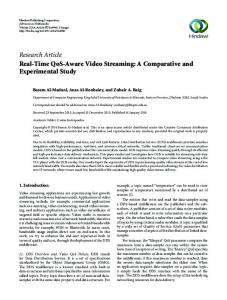
Figure 2. Shows bending loss at 1550 nm for bending radii of 15, 10, 7.5 and 5 mm as a function of MFD for step- index profile. In SMF bending loss is 0.1 dB for ten turns of winding at a specified radius. The MFD of the SMF complying with the criterion for a bending radius of 7.5 mm is 6.8 𝜇𝑚 at 1330 nm. The resultant splice loss the standard SMF is 0.39 dB and an MFD of 9.2 𝜇𝑚. A total splice loss may be a double of the value, 0.78 dB, since the Trench index fiber and standard SMF are spliced at two points, i.e., at the end of a drop cable and at the input of the ONU. A loss penalty close to 1 dB may be serious for the worst case design of an access network. As a result, other solutions are required in order to achieve a low-bend- loss fiber with an allowable bending radius of less than or equal to 7.5 mm.
III.
Fiber with a Trench-Index Profile
Figure 3. Schematics of (a) trench-index profile, (b) Cross section view of trench assisted fiber.
A trench- index profile, which has an index trench around a triangular core with an inner cladding, has been originally proposed for a dispersion-shifted fiber [W. A. Reed et al. (1987)]. We have reconsidered and proposed the profile in order change for bending and splice losses in a single mode fiber [K. Saitoh et al. (2005)]. In Figure 3, shows the trenchindex profile, where Δ1 , Δ2 , and Δ3 are the relative refractive indices between the corresponding layers and the cladding, and r, r1, and 𝑟2 are the radii of the layers. In the trench- index profile, Δ1 was varied from 0.35% to 0.70%, and r was determined such that the cabled cutoff wavelength became 1332 nm, whereas Δ2 = 0.02%, Δ3 = −0.25%, 𝑟1 /r = 3.5, and 𝑟2 /r = 5.5.
Figure 4. Shows bending loss at 1550 nm for bending radii r of 15, 10, 7.5 and 5 mm as a function of MFD for trench- index profile. In Figure 4, shows simulated bending loss as a function of MFD for bending radii of 5, 7.5, 10 and 15 mm for trench- index profile. In this structure variation of bending losses gradually decreases as well as MFD increases at constant set of parameters.
VI. Comparison: standard SMF and trench assisted fiber We have analyzed of SMF and TA-SMF. It can be seen from Figure 2, SMF and Figure 4, TA-SMF. The fiber with a trench- index profile can achieve a bending loss smaller than that in a step- index profile for a range of MFD larger than 8.9 𝜇𝑚. The bending loss originates from a power leakage that occurs at the mode- field edge, where the effective index of a bent fiber exceeds the equivalent index of a propagating mode in the fiber [L. B. Jeunhomme et al. (1989)]. 1. PARAMETER COMPARISIONS TABLE Characterized parameters
Unit
Effective MFD Cut-off wavelength Splice loss in average r = 15 Bending r = 10 loss r = 7.5 r=5
μm μm dB dB/km dB/km dB/km dB/km
Wavelength 1550 --1550 1550 1550 1550 1550
Sample S-SMF
TA-SMF
9.2 1.332 0.30 0.006 0.009 0.049 0.311
7.9 1.93 0.22 0.001 0.002 0.004 0.011
The low-bending- loss features of the trench- index profile fiber can be illustrated as follows. The measurement results of step-index and trench- index fibers shown in Table 1. Addition of the trench to the step- index profile does not greatly affect the mode field of the original stepindex fiber, as long as the trench is located apart from the core, as shown in Figure 5. The trench in the cladding suppresses the increase of the effective index at the cladding around the edge of the mode field. The cutoff wavelengths of the fibers were measured by the multimode reference technique. This is because the bending loss of the second-order mode was small as well, making it difficult to determine the cutoff wavelength when the popular bend reference technique was used. The calculated splice losses were obtained from direct convolution of the computed transverse-mode fields for the two fibers, a sample, and standard SMF.
Figure 5. Shows MFDs and 1550 nm for with and without trench as a function of normalized distance between the core and the trench 𝑟1 /r for Δ1 =0.70%, Δ2 = 0.02%, Δ3 = −0.25%, and 𝑟3 − 𝑟2 /r = 2.0. A step-index fiber achieved a bending loss is 0.09 dB/km for a bending radius of 10 mm at 1550 nm and splice loss is 0.30 dB at 1550 nm. The trench-index fiber achieved a bending loss is 0.02 dB/km for a bending radius of 10 mm at 1550 nm and splice loss is 0.22 dB at 1330 nm. However, a trench- index profile has a lower bending loss and splice loss then stepindex-profile fiber. This result apparently indicates the advantage of trench-index profile over step- index profile. Consequently, fiber has simultaneously shown a reduced bending loss at a designated bending radius and a suppressed splice loss. The trench- index-profile fiber shows a bending loss smaller than that of the step- index-profile fiber. This insensitivity to bending radius for the trench- index profile fiber is effective for suppressing additional loss increase by unexpected strong bending occurrences in fiber installa tion. Drop and indoor cables including the fibers have been fabricated experimentally [S. Tanaka et al. (2003)]. Excellent bending characteristics and operability have been demonstrated.
a. Bending Performance Generally, bending losses of any type of fiber exponentially decrease with bending radius and increase with operating wavelength. To determine the bending performance of two types of fibers, we analyze bending losses of step- index fiber and trench-assisted fiber with different bending radii at selected wavelength (𝜆 = 1550 nm in Figure 3, above), as well as the MFD
of 𝑟 = 5 mm to 𝑟 = 15 mm. the trench-assisted fiber present a highly improved bending loss behavior compared to standard SMF. As the measurement showed, the trench assisted type can be bending down to 𝑟 = 10 mm while staying below 0.1 db per full tern up to 1625 nm wavelength. These measurements clearly indicate that this type of low bend fiber could make fiber installations less critical, and more flexible as allow bending around tighter corners.
b. Mode field Reducing bending loss can normally be done by increasing the refractive index difference between core and cladding. However by doing so, it’s very difficult to maintain the mode field size and stay single mode at the same time. The trench assisted approaches solve this by having the same core cladding structure in the center as the standard SMF, but adding low index trench around the core in Figure 2. Proper design of the position of this trench will only impact the optical bend loss without seriously modifying the fundamental mode properties, such as mode field diameter, attenuation characteristics, and dispersion properties. The resulting means value of the mode sizes become slightly different (9.2 𝜇𝑚 for the standard SMF, 7.9 𝜇𝑚 for the trench assisted). The trench assisted has the potential to allow around tight corners without noticeable increase in attenuation.
IV.
Conclusion
The low bending- loss fibers for fiber to- the-home have been introduced and reviewed. The trench assisted fiber compared with respect to the optical properties of standard single mode fibers. A step- index-profile fiber realizes an allowable bending radius of 15 mm and will be used widely in access networks. A trench assisted fiber can achieve a negligible bending loss for a bending radius of 7.5 mm. A trench assisted fiber practically has low mechanical splice loss and MFD then the standard SMF. They have shown better performances under bending, as well as some extent their compatibility to standard SMF. A Trench-assisted fiber has better bending performance and the big advantage in loss and bend critical FTTH application. A Trench assisted fiber is recommended for bend and loss critical applications as they are a real advance to current standard single mode fibers.
References [1]
[2]
[3]
P. Montha, R. Maneekut, P. Kaewplung, The performance limitation of 10-Gbps-perchannel-based coarse wavelength division multiplexed passive optical network, in Proc. of 16th International Conference on Advanced Communication Technology (ICACT), 1089 - 1092 (2014). K. Sato, Optical fiber and cable technologies supporting FTTH, in Proc. of Optoelectronics and Communications Conf./Conf. Optical Internet (OECC/COIN), 13D2-1 (2004). D.Z. Chen, W.R Belben, J.B. Gallup, C. Mazzali, Requirements for Bend Insensitive Fibers for Verizon's FiOS and FTTH applications, in Proc. of Optical Fiber communication/National Fiber Optic Engineers Conference (OFC/NFOEC), 1 - 7( 2008).
[4]
[5]
[6]
[7]
[8]
[9]
[10] [11] [12] [13]
Lei Yao, T.A Birks, J.C. Knight, Low bend loss in tightly-bent optical fibers through adiabatic bend transitions, in Proc. of Lasers and Electro-Optics and Conference on Quantum electronics and Laser Science Conference. (CLEO/QELS), 1 - 2 (2009). Franzen, L. Douglas, R. Srivastava, Determining the mode- field diameter of singlemode optical fiber: An interlaboratory comparison, J. Light. Tech. 3, 1073 - 1077 (2003). S. Matsuo, M. Ikeda, and K. Himeno, Bend-insensitive and low-spliceloss optical fiber for indoor wiring in FTTH, in Proc. of Optical Fiber Communication Conference (OFC) 818-826 (2004). T. Akiyoshi, K. Hamada, N. Akasaka, M. Dazai, and Y. Terasawa, Development of non- flammable optical fiber with improved macrobending performance, in Proc. of IEICE Society Conf., B-10-23 (2002). K. Ichii, N. Yamada, M. Fujimaki, K. Harada, and K. Tsurusaki, Characteristics of low macrobending- loss SMF (FutureGuide-SR15E) with low water peak, in Proc. of IEICE General Conf., B-10-2 (2004). H. Kutami, S. Matsuo, K. Himeno, and K. Ohashi, Low-bending- loss and suppressedsplice- loss optical fibers for FTTH indoor wiring, in Proc. of Tech. Dig. Optoelectronics and Communications Conf./Conf. Optical Internet (OECC/COIN) 13D2-2 (2004). W. A. Reed, L. G. Cohen, and H. Shang, Tailoring optical characteristics of dispersionshifted lightguides for applications near 1.55 μm, AT&T Tech. J., 65, 105–122 (1987). K. Saitoh, Y. Tsuchida, and M. Koshiba, Bending- insensitive single- mode hole-assisted fibers with reduced splice loss, Optics Letters, 30, 1779-1781 (2005). L. B. Jeunhomme, Single-Mode Fiber Optics, 2nd edition, Marcel Dekker, New York (1989) S. Tanaka, S. Shiobara, T. Shimomichi, and K. Ohashi, A bend-resistant non- metallic drop cable for FTTH, in Proc. of 52nd Int. Wire and Cable Symp. (IWCS/Focus), 438– 443 (2003).