International Journal of Power Electronics and Drive System (IJPEDS) Vol. 7, No. 1, March 2016, pp. 56~65 ISSN: 2088-8694
56
Comparison of PI and PID Controlled Bidirectional DC-DC Converter Systems K.C. Ramya*, V. Jegathesan** * Department of Electrical and Electronics Engineering, Karunya University ** Department of Electrical and Electronics Engineering, Karunya University
Article Info
ABSTRACT
Article history:
This paper deals with comparison of responses of the PI and the PID controlled bidirectional DC-DC converter systems. A coupled inductor is used in the present work to produce high gain. Open loop and closed loop controlled systems with PI and PID controllers are designed and simulated using Matlab tool. The principles of operation and simulation case studies are discussed in detail. The comparison is made in terms of rise time, fall time, peak overshoot and steady state error.
Received Jul 22, 2015 Revised Dec 14, 2015 Accepted Jan 8, 2016 Keyword: Bidirectional DC-DC Converter Coupled Inductor Proportional Integral Proportional Integral Derivative
Copyright © 2016 Institute of Advanced Engineering and Science. All rights reserved.
Corresponding Author: K.C. Ramya, Departement of Electrical and Electronics Engineering, Karunya University, Coimbatore, India. Email:
[email protected]
1.
INTRODUCTION The The High voltage gain converter is widely used in many applications such as renewable energy sources, hybrid electric vehicles, battery chargers etc., [1-9]. However the voltage gain is limited by various facts such as power switches, inductor and capacitor. The high step up and step down voltage gain can be obtained from isolated converter by tuning the ratio of the transformer [11]. It results in high voltage stress on switches which in turns lead to low efficiency. In non-isolated applications, the non-isolated bidirectional dc–dc converters, such as multilevel type requires twelve switches. For the requirement of high step-up and step-down voltage gains, more number of switches has to be added. This makes the circuit more complicated. In three-level type, the voltage stress on the switches is only half of the conventional type [10]. But, the step-up and step-down voltage gains are low. In SEPIC/zeta type, the conversion efficiency is low because it is a combination of two power stages. The switched capacitor and coupled inductor type can afford high step up and step down voltage gains but their circuit configuration is very complicated [12-20]. A conventional bi-directional converter (BDC) with coupled inductor is shown in Figure 1.
Journal homepage: http://iaesjournal.com/online/index.php/IJPEDS
57
ISSN: 2088-8694
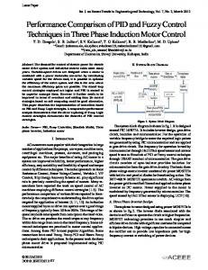
Figure 1. Conventional BDC Boost/Buck Converter This converter is very simple. But it has the problem of the voltage and current ripples at its input and output. Hence, a large capacitor or inductor filters are required to suppress the ripples. But this result in high loss and low efficiency. Hence in order to overcome this drawback of the conventional converter, a novel bidirectional converter [19-30] is proposed, as shown in Figure 2.
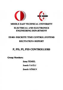
Figure 2. Proposed Bidirectional DC-DC Converter The Proposed converter consist of two switches namely S1 and S2, a coupled inductor with same winding turns in the primary and secondary. S3 is the synchronous rectifier. The proposed converter provides: 1) Higher step-up and step-down voltage gains and 2) lower average value of the switch current under same electric specifications. The on-state resistance RDS(ON) of the switches and the equivalent series resistances of the coupled inductor and capacitors are ignored; the capacitor is sufficiently large; and the voltages across the capacitor can be treated as constant. The above literature does not deal with ripple reduction using Pi-filter. This work proposes Pi-filter for ripple reduction. Also the above papers do not deal with the comparison between PI and PID controlled bidirectional DC to DC converter systems. This work tries to identify a suitable controller for closed loop system. This paper is organized as follows: Analysis of Step-up mode is given in section 2. The simulation results in boost mode and buck mode are given in section 3. The work is concluded in section 4.
2.
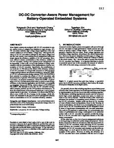
STEP-UP MODE The proposed converter in step-up mode is shown in Figure 3. The pulse width modulation (PWM) technique is used to control the switches S1 and S2 simultaneously.
Figure 3. Proposed converter in step-up mode Thus, the inductance of the coupled inductor can be expressed as
IJPEDS Vol. 7, No. 1, March 2016 : 56 – 65
IJPEDS
ISSN: 2088-8694 L1 = L2 = L
58
(1)
The mutual inductance M of the coupled inductor is given by M = K√(L1L2) = KL
(2)
Where k is the coupling co-efficient of coupled inductor. Hence the voltage across the primary and secondary winding of the coupled inductor can be expressed as v L1 L 1
v L2 M
d i L1 dt d i L1 dt
d iL2
M
dt
L2
d iL2 dt
L
d i L1
kL
dt
kL
d i L1 dt
L
d iL2 dt
(3)
d iL2 dt
(4)
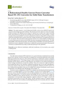
Mode I: During this mode, Switch S1 and S2 are ON and S3 is in OFF condition, as shown in figure3a.
Figure 3a. Proposed Converter in Mode 1 Hence, the low voltage side VL is transferred to the coupled inductor and the energy stored in the capacitor CH is discharged to the load. Thus the voltage across L1 and L2 are obtained as follows vL1 = vL2 = VL
(5)
Substituting (3) and (4) into (5), yielding
d i L1 t dt
d i L 2 t dt
VL , t t t1 1 k L 0
(6)
Mode II: During this mode, switches S1 and S2 are OFF and S3 is ON condition as shown in Figure 3b.
Figure 3b. Proposed Converter in Mode 2 The voltage side VL and the coupled inductor are in series and their energies are transferred to capacitor CH and to the load. Thus the voltage and current at this mode are given as follows iL1 = iL2
(7)
Comparison of PI and PID Controlled Bidirectional DC-DC Converter Systems (K.C. Ramya)
59
ISSN: 2088-8694
vL1 + vL2 = VL – VH
(8)
Substituting (3) and (4) into (8), yielding
d i L1 t dt
d i L2 t dt
VL VH , t1 t t 2 2 1 k L
(9)
By using the state space averaging method, the following equation is derived from (6) and (9) DVL k L
1
1
D
V L
2 1 k
V
L
H
0
(10)
Thus the voltage gain during the step up mode is given as
V 1 D G C C M s te p u p H 1 D VL
(11)
3.
SIMULATION RESULTS The simulation of the bidirectional DC-DC converters was performed for boost mode & buck mode. The results are presented here. 3.1. Boost Mode The open loop controlled DC-DC converter system is shown in Figure 4a. A step change of 5V is applied at the input as shown in Figure 4b.The change in output voltage is shown in Figure 4c. The output voltage changes by 10V.The load current increases by 1A as shown in Figure 4d. The change in output power is shown in Figure 4e. The power increases from 90W to 170W. The increase in power is due to the increase in the input voltage.
Figure 4a. Circuit Diagram for the Boost Mode
Figure 4b. Input Voltage
IJPEDS Vol. 7, No. 1, March 2016 : 56 – 65
Figure 4c. Output Voltage
IJPEDS
ISSN: 2088-8694
Figure 4d. Output Current
60
Figure 4e. Output Power
Closed loop PI controlled system is shown in Figure 5a. Output voltage is sensed and it is compared with the reference voltage to obtain the error.The error is applied to a PI controller.The output of PI controller is compared with time base voltage to produce updated pulses.
Figure 5a. Circuit Diagram for the Closed loop PI Controller in the Boost Mode Voltage control is used to maintain a value of 30V at the output. The variation of input voltage is shown in Figure 5b.The input voltage increases from 15V to 22V.The output voltage, current and power are shown in figures 5c, 5d & 5e respectively. The output voltage gets corrected and comes back to the normal value.
Figure 5b. Input Voltage
Figure 5d. Output Current
Figure 5c. Output Voltage
Figure 5e. Output Power
The PI controller is replaced by PID controller.The closed loop PID controlled DC to DC converter operating in boost mode is shown in Figure 6a.The variation of input voltage is shown in Figure 6b.The curves of output voltage, output current and output power are shown in figures 6c, 6d & 6e respectively. The output gets settled quickly with reduced overshoot as compared with PI controlled system. Comparison of PI and PID Controlled Bidirectional DC-DC Converter Systems (K.C. Ramya)
61
ISSN: 2088-8694
Figure 6a. Circuit Diagram for the Closed loop PID Controller in the Boost Mode
Figure 6b. Input Voltage
Figure 6c. Output Voltage
Figure 6d. Output Current
Figure 6e. Output Power
3.2. Buck Mode The open loop controlled DC-DC converter operating in buck mode is shown in Figure 7a. The variation of input voltage, output voltage, output current and output power are shown in figures 7b, 7c, 7d & 7e respectively. The output voltage increases by 5V.The power increases by 20W.
Figure 7a. Circuit Diagram for the Buck Mode
Figure 7b. Input Voltage
IJPEDS Vol. 7, No. 1, March 2016 : 56 – 65
Figure 7c. Output Voltage
IJPEDS
ISSN: 2088-8694
Figure 7d. Output Current
62
Figure 7e. Output Power
The closed loop PI controlled DC to DC converter system is shown in Figure 8a. The variation in input voltage is shown in Figure 8b.The input voltage increases from 30V to 37V.The output voltage in buck mode is shown in Figure 8c. The output voltage is 15V.Output current and output power are shown in figures 8d & 8e respectively. The current is 3.5A and the output power is 48W.
Figure 8a. Circuit Diagram for the Closed loop PI Controller in the Buck Mode
Figure 8b. Input Voltage
Figure 8d. Output Current
Figure 8c. Output Voltage
Figure 8e. Output Power
The closed loop PID controlled DC to DC converter is shown in Figure.9a. The input voltage increases from 30V to 36V as shown in Figure.9b.The curves of output voltage, output current and output power are shown in figures 9c, 9d & 9e respectively. The output reaches the required value due to the closed loop control action.
Comparison of PI and PID Controlled Bidirectional DC-DC Converter Systems (K.C. Ramya)
63
ISSN: 2088-8694
Figure 9a. Circuit Diagram for the Closed loop PID Controlled system in Buck Mode
Figure 9c. Output Voltage
Figure 9b. Input Voltage
Figure 9d. Output Current
Figure 9e. Output Power
The summary of boost mode and buck mode are given in Table 1 & 2 respectively. Table 1. Summary of Boost Mode Boost Mode PI Controller PID Controller
Rise Time, Tr (Secs) 0.050 0.045
Settling Time, Ts (Secs) 0.81 0.6
Peak Time, Tp (Secs) 0.53 0.51
Steady State Error, Ess (Volts) 0.8 0.5
Table 2. Summary of Buck Mode Buck Mode PI Controller PID Controller
Rise Time, Tr (Secs) 0.08 0.06
Settling Time, Ts (Secs) 1.21 1.12
Peak Time, Tp (Secs) 0.83 0.63
Steady State Error, Ess (Volts) 0.92 0.71
It can be seen that the rise time, the settling time, the peak time and the steady state error are reduced by using the PID controller.
4.
CONCLUSION Closed loop controlled bidirectional DC-DC converter operating in boost mode and buck mode are designed and simulated successfully. Closed loop system is simulated with PI and PID controllers.The converter has bidirectional ability and high voltage gain. From the results, it was observed that the response was better with PID controller than PI controller since PID controlled system produces reduced settling time and steady state error.The contribution of this work is to reduce the ripple using Pi-filter and improve IJPEDS Vol. 7, No. 1, March 2016 : 56 – 65
IJPEDS
ISSN: 2088-8694
64
dynamic response using PID controller.The scope of the present work is the simulation with PI and PID controllers. The fuzzy logic based converter will be simulated in future. The comparison will be made between PID and fuzzy based converter systems.
REFERENCES [1] [2] [3] [4] [5] [6] [7] [8] [9] [10] [11] [12] [13] [14] [15] [16] [17] [18] [19] [20] [21] [22] [23] [24] [25] [26] [27]
M.B. Camara, H. Gualous, F. Gustin, A. Berthon, and B. Dakyo, “DC/DC converter design for supercapacitor and battery power management in hybrid vehicle applications—Polynomial control strategy”, IEEE Trans. Ind. Electron., vol. 57, no. 2, pp. 587–597, Feb. 2010. T. Bhattacharya, V.S. Giri, K. Mathew, and L. Umanand, “Multiphase bidirectional flyback converter topology for hybrid electric vehicles”, IEEE Trans. Ind. Electron., vol. 56, no. 1, pp. 78–84, Jan. 2009. Z. Amjadi and S.S. Williamson, “A novel control technique for a switched-capacitor-converter-based hybrid electric vehicle energy storage system”, IEEE Trans. Ind. Electron., vol. 57, no. 3, pp. 926–934,Mar. 2010. F.Z. Peng, F. Zhang, and Z. Qian, “A magnetic-less dc–dc converter for dual-voltage automotive systems”, IEEE Trans. Ind. Appl., vol. 39, no. 2, pp. 511–518, Mar./Apr. 2003. A. Nasiri, Z. Nie, S.B. Bekiarov, and A. Emadi, “An on-line UPS system with power factor correction and electric isolation using BIFRED converter”, IEEE Trans. Ind. Electron., vol. 55, no. 2, pp. 722–730, Feb. 2008. L. Schuch, C. Rech, H.L. Hey, H.A. Grundling, H. Pinheiro, and J.R. Pinheiro, “Analysis and design of a new highefficiency bidirectional integrated ZVT PWM converter for DC-bus and battery-bank interface”, IEEE Trans. Ind. Appl., vol. 42, no. 5, pp. 1321–1332, Sep./Oct. 2006. X. Zhu, X. Li, G. Shen, and D. Xu, “Design of the dynamic power compensation for PEMFC distributed power system”, IEEE Trans. Ind. Electron., vol. 57, no. 6, pp. 1935–1944, Jun. 2010. G. Ma, W. Qu, G. Yu, Y. Liu, N. Liang, and W. Li, “A zero-voltageswitching bidirectional dc–dc converter with state analysis and softswitching-oriented design consideration”, IEEE Trans. Ind. Electron.,vol. 56, no. 6, pp. 2174–2184, Jun. 2009. F.Z. Peng, H. Li, G.J. Su, and J.S. Lawler, “A new ZVS bidirectional dc–dc converter for fuel cell and battery application”, IEEE Trans. PowerElectron., vol. 19, no. 1, pp. 54–65, Jan. 2004. K. Jin, M. Yang, X. Ruan, and M. Xu, “Three-level bidirectional converter for fuel-cell/battery hybrid power system”, IEEE Trans. Ind. Electron., vol. 57, no. 6, pp. 1976–1986, Jun. 2010. R. Gules, J.D.P. Pacheco, H.L. Hey, and J. Imhoff, “A maximum power point tracking system with parallel connection for PV stand-alone applications”, IEEE Trans. Ind. Electron., vol. 55, no. 7, pp. 2674–2683, Jul. 2008. Z. Liao and X. Ruan, “A novel power management control strategy for stand-alone photovoltaic power system”, in Proc. IEEE IPEMC, 2009, pp. 445–449. S. Inoue and H. Akagi, “A bidirectional dc–dc converter for an energy storage system with galvanic isolation”, IEEE Trans. Power Electron., vol. 22, no. 6, pp. 2299–2306, Nov. 2007. L.R. Chen, N.Y. Chu, C.S. Wang, and R.H. Liang, “Design of a reflexbasedbidirectional converter with the energy recovery function”, IEEE Trans. Ind. Electron., vol. 55, no. 8, pp. 3022–3029, Aug. 2008. S.Y. Lee, G. Pfaelzer, and J.D.Wyk, “Comparison of different designs of a 42-V/14-V dc/dc converter regarding losses and thermal aspects”, IEEE Trans. Ind. Appl., vol. 43, no. 2, pp. 520–530, Mar./Apr. 2007. K. Venkatesan, “Current mode controlled bidirectional flyback converter”, in Proc. IEEE Power Electron. Spec. Conf., 1989, pp. 835–842. T. Qian and B. Lehman, “Coupled input-series and output-parallel dual interleaved flyback converter for high input voltage application”, IEEE Trans. Power Electron., vol. 23, no. 1, pp. 88–95, Jan. 2008. G. Chen, Y.S. Lee, S.Y.R. Hui, D. Xu, and Y. Wang, “Actively clamped bidirectional flyback converter”, IEEE Trans. Ind. Electron., vol. 47, no. 4, pp. 770–779, Aug. 2000. F. Zhang and Y. Yan, “Novel forward-flyback hybrid bidirectional dc–dc converter”, IEEE Trans. Ind. Electron., vol. 56, no. 5, pp. 1578–1584,May 2009. H. Li, F.Z. Peng, and J.S. Lawler, “A natural ZVS medium-power bidirectional dc–dc converter with minimum number of devices”, IEEE Trans. Ind. Appl., vol. 39, no. 2, pp. 525–535, Mar. 2003. B.R. Lin, C.L. Huang, and Y.E. Lee, “Asymmetrical pulse-width modulation bidirectional dc–dc converter”, IET Power Electron., vol. 1, no. 3, pp. 336–347, Sep. 2008. Y. Xie, J. Sun, and J.S. Freudenberg, “Power flow characterization of a bidirectional galvanically isolated highpower dc/dc converter over a wide operating range”, IEEE Trans. Power Electron., vol. 25, no. 1, pp. 54–66, Jan. 2010. I.D. Kim, S.H. Paeng, J.W. Ahn, E.C. Nho, and J.S. Ko, “New bidirectional ZVS PWM sepic/zeta dc–dc converter”, in Proc. IEEE ISIE, 2007, pp. 555–560. Y.S. Lee and Y.Y. Chiu, “Zero-current-switching switched-capacitor bidirectional dc–dc converter”, Proc. Inst. Elect. Eng.—Elect. Power Appl., vol. 152, no. 6, pp. 1525–1530, Nov. 2005. R.J. Wai and R.Y. Duan, “High-efficiency bidirectional converter for power sources with great voltage diversity”, IEEE Trans. Power Electron., vol. 22, no. 5, pp.1986–1996, Sep. 2007. L.S. Yang, T.J. Liang, and J.F. Chen, “Transformerless dc–dc converters with high step-up voltage gain”, IEEE Trans. Ind. Electron., vol. 56, no. 8,pp. 3144–3152, Aug. 2009. Lung-Sheng Yang and Tsorng-Juu Liang, “Analysis and Implementation of novel bidirectional dc-dc converter”, IEEE Trans.Ind.Electron, vol. 59, no. 1, Jan. 2012.
Comparison of PI and PID Controlled Bidirectional DC-DC Converter Systems (K.C. Ramya)
65
ISSN: 2088-8694
[28] Vu Tran, Mufeed MahD, “Modeling and Analysis of Transformerless High Gain Buck-boost DC-DC Converters”, Power Electronics and Drive Systems (IJPEDS), Vol. 4, No. 4, pp. 528 – 535, Dec . 2014. [29] Ebrahim Babaei, Azadeh Mofidi, Sara Laali,”Analysis of the Transformerless Boost DC-DC Converter with High Voltage Gain in Different Operating Modes and Critical Inductance Calculations”, Bulletin of Electrical Engineering and Informatics, Vol. 4, No. 2, pp. 136~146, June 2015. [30] Azadeh Ahmadi, Rahim Ildarabadi,”A Review to AC Modeling and Transfer Function of DC-DC Converters”, TELKOMNIKA Indonesian Journal of Electrical Engineering,Vol.13, No.2, pp.271~281, Feb. 2015.
BIOGRAPHIES OF AUTHORS K.C. Ramya has done her B.E from Mailam Engineering College, Mailam, India in the year 2002 and M.E from Sathyabama University, Chennai, India in the year 2010. Presently she is a research scholar at Karunya University, Coimbatore, India. She is doing her research in the area of bidirectional DC to DC Converters applied to Electrical Vehicles.
V. Jegathesan has obtained his B.E and M.E degree from Bharathiar University, Coimbatore, India in the year 1999 and 2002 respectively. He obtained his Ph.D from Anna University, Chennai, India in the year 2010. He is presently working as an Associate Professor of EEE Department in Karunya University, Coimbatore, India. He is a fellow member of ISTE, Member of IACSIT and Member of IAENG. He has authored text book on Basic Electrical and Electronics Engineering. He has published various research papers in reputed Journals. His research area includes Electric Circuits and Networks, Power Electronics, Development of Heuristic Algorithms for Power Electronic Applications and Application of Power Electronics to Renewable Energy.
IJPEDS Vol. 7, No. 1, March 2016 : 56 – 65