Jun 17, 2002 ... The first three volumes of this handbook currently focus on, but are not ..... 3.2.3
High temperature properties of continuous ceramic fibers .
NOT MEASUREMENT SENSITIVE MIL-HDBK-17-5 Volume 5 of 5 17 JUNE 2002
DEPARTMENT OF DEFENSE HANDBOOK
COMPOSITE MATERIALS HANDBOOK VOLUME 5. CERAMIC MATRIX COMPOSITES
This handbook is for guidance only. Do not cite this document as a requirement.
AMSC N/A
AREA CMPS
DISTRIBUTION STATEMENT A. Approved for public release; distribution unlimited.
MIL-HDBK-17-5 Volume 5, Foreword / Table of Contents
FOREWORD 1. This Composite Materials Handbook Series, MIL-HDBK-17, are approved for use by all Departments and Agencies of the Department of Defense. 2. This handbook is for guidance only. This handbook cannot be cited as a requirement. If it is, the contractor does not have to comply. This mandate is a DoD requirement only; it is not applicable to the Federal Aviation Administration (FAA) or other government agencies. 3. Every effort has been made to reflect the latest information on polymer (organic), metal, and ceramic composites. The handbook is continually reviewed and revised to ensure its completeness and currentness. Documentation for the secretariat should be directed to: Materials Sciences Corporation, MIL-HDBK-17 Secretariat, 500 Office Center Drive, Suite 250, Fort Washington, PA 19034.. 4. MIL-HDBK-17 provides guidelines and material properties for polymer (organic), metal, and ceramic matrix composite materials. The first three volumes of this handbook currently focus on, but are not limited to, polymeric composites intended for aircraft and aerospace vehicles. Metal matrix composites (MMC) and ceramic matrix composites (CMC), including carbon-carbon composites (C-C) are covered in Volume 4 and Volume 5 , respectively. 5. This standardization handbook has been developed and is being maintained as a joint effort of the Department of Defense and the Federal Aviation Administration. 6. The information contained in this handbook was obtained from materials producers, industry, reports on Government sponsored research, the open literature, and by contact with research laboratories and those who participate in the MIL-HDBK-17 coordination activity. 7. All information and data contained in this handbook have been coordinated with industry and the U.S. Army, Navy, Air Force, NASA, and Federal Aviation Administration prior to publication. 8. Copies of this document and revisions thereto may be obtained from the Document Automation and Production Service (DAPS), Bldg. 4D, (DODSSP/ASSIST), 700 Robbins Avenue, Philadelphia, PA 19111-5094. 9. Beneficial comments (recommendations, additions, deletions) and any pertinent data which may be of use in improving this document should be addressed to: U.S. Army Research Laboratory, Weapons and Materials Research Directorate, Attn: AMSRL-WM-MA, Aberdeen Proving Ground, MD 210055069, by using the Standardization Document Improvement Proposal (DD Form 1426) appearing at the end of this document or by letter.
ii
MIL-HDBK-17-5 Volume 5, Foreword / Table of Contents
CONTENTS PART A. INTRODUCTION AND GUIDELINES PART B. DESIGN AND SUPPORTABILITY PART C. TESTING PART D. DATA REQUIREMENTS AND DATA SETS APPENDIX A. DERIVATION OF THE RESIDUAL STRENGTH REDUCTION EXPRESSIONS FOR LCF AND RUPTURE LOADINGS Page Forward.......................................................................................................................................................... ii
PART A. INTRODUCTION AND GUIDELINES ........................................................................................... 2 1 MIL-17 GUIDELINES AND PROCEDURES......................................................................................... 2 1.1 INTRODUCTION ....................................................................................................................... 2 1.1.1 Objectives of Ceramic Matrix Composite (CMC) Working Groups ............................. 2 1.1.1.1 Objectives and tasks for Data Review Working Group ............................. 3 1.1.1.2 Vision, goals and objectives for Materials and Processes Working Group........................................................................................... 3 1.1.1.3 Vision, goals and objectives for Structural Analysis & Design Codes Working Group ............................................................................... 4 1.1.1.4 Vision, goals and objectives for Testing Working Group ........................... 4 1.2 PURPOSE ................................................................................................................................. 4 1.3 SCOPE ...................................................................................................................................... 6 1.3.1 Part A: Introduction and Guidelines............................................................................ 6 1.3.2 Part B: Design Supportability ..................................................................................... 6 1.3.3 Part C: Testing............................................................................................................ 6 1.3.4 Part D: Data Requirements and Data Sets ................................................................ 6 1.4 USE OF THE DOCUMENT AND LIMITATIONS........................................................................ 7 1.4.1 Source of information .................................................................................................. 7 1.4.2 Use of data and guidelines in applications.................................................................. 7 1.4.3 Strength properties and allowables terminology ......................................................... 7 1.4.4 Use of References....................................................................................................... 8 1.4.5 Use of tradenames and product names ...................................................................... 8 1.4.6 Toxicity, health hazards, and safety ............................................................................ 8 1.4.7 Ozone depleting chemicals ......................................................................................... 8 1.5 APPROVAL PROCEDURES...................................................................................................... 8 1.6 SYMBOLS, ABBREVIATIONS, AND SYSTEMS OF UNITS ..................................................... 9 1.6.1 Symbols and abbreviations ....................................................................................... 10 1.6.1.1 Constituent properties ............................................................................. 14 1.6.1.2 Laminae and laminates ........................................................................... 15 1.6.1.3 Subscripts ................................................................................................ 16 1.6.1.4 Superscripts............................................................................................. 17 1.6.1.5 Acronyms ................................................................................................. 17 1.6.2 System of units.......................................................................................................... 20 1.7 DEFINITIONS .......................................................................................................................... 20 2 INTRODUCTION, HISTORY AND OVERVIEW ................................................................................. 43 2.1 HISTORY AND OVERVIEW .................................................................................................... 43 2.2 APPLICATIONS ....................................................................................................................... 44 3 PROCESSING, CHARACTERIZATION AND MANUFACTURING .................................................... 47 3.1 CMC SYSTEMS, PROCESSING, PROPERTIES AND APPLICATIONS ................................ 47 3.1.1 CMC processing methods ......................................................................................... 47
iii
MIL-HDBK-17-5 Volume 5, Foreword / Table of Contents 3.1.1.1 Chemical vapor infiltration CMCs ............................................................ 47 3.1.1.1.1 CVI fabrication technique ........................................................... 47 3.1.1.1.2 Typical properties for CVI CFCCs .............................................. 48 3.1.1.1.3 Typical applications for CVI CFCCs ........................................... 50 3.1.1.2 Directed metal oxidation (DIMOX™) ....................................................... 50 3.1.1.2.1 Basic processing procedures for DIMOX™ ............................... 50 3.1.1.2.2 Typical properties of DIMOX™................................................... 51 3.1.1.2.3 Typical applications for DIMOX™ .............................................. 51 3.1.1.3 Polymer derived ceramics ....................................................................... 51 3.1.1.3.1 Introduction................................................................................. 51 3.1.1.3.2 Fabrication.................................................................................. 52 3.1.1.4 Carbon-carbon composites ..................................................................... 55 3.1.1.5 Oxide systems –sinter/hot press ............................................................. 56 3.1.1.6 Sol-gel processing ................................................................................... 56 3.1.1.6.1 Introduction................................................................................. 56 3.1.1.6.2 Single oxide compositions.......................................................... 57 3.1.1.6.3 Advantages and disadvantages of sol-gel processing ............... 57 3.1.1.6.4 Drying control agents and fillers................................................. 59 3.1.1.6.5 Sol-gel processing of 2-D structures .......................................... 60 3.1.1.6.6 Sol-gel processing of 3-D structures .......................................... 60 3.1.1.6.7 Summary .................................................................................... 61 3.1.1.7 Melt infiltration.......................................................................................... 61 3.1.1.7.1 Resin infiltration, pyrolysis, and reaction.................................... 61 3.1.1.7.2 Slurry casting.............................................................................. 62 3.1.1.8 Reaction processing ................................................................................ 62 3.1.1.9 Fibrous monoliths (FMs).......................................................................... 63 3.1.1.9.1 Introduction................................................................................. 63 3.1.1.9.2 Macrostructure of fibrous monoliths ........................................... 64 3.1.1.9.3 Mechanical properties of fibrous monoliths................................ 65 3.1.1.9.4 Thermal properties of fibrous monoliths..................................... 66 3.1.1.9.5 Applications for fibrous monoliths .............................................. 67 3.1.1.10 Hybrid systems ...................................................................................... 67 3.2 FIBER/REINFORCEMENT SYSTEMS AND TECHNOLOGY................................................. 67 3.2.1 Introduction – the role and function of reinforcements in CMCs ............................... 67 3.2.2 Continuous fibers ...................................................................................................... 67 3.2.2.1 Oxide fibers.............................................................................................. 67 3.2.2.2 SiC monofilaments................................................................................... 70 3.2.2.3 Small diameter SiC-based fibers ............................................................. 72 3.2.2.4 Carbon fibers ........................................................................................... 73 3.2.2.4.1 Introduction and applications ..................................................... 73 3.2.2.4.2 Structure and general properties of carbon fibers...................... 75 3.2.2.4.3 Fabrication of carbon fibers........................................................ 76 3.2.2.4.4 Availability and sources of carbon fibers .................................... 79 3.2.2.4.5 Specific properties of carbon fibers ............................................ 79 3.2.3 High temperature properties of continuous ceramic fibers ....................................... 82 3.2.3.1 Carbon fibers ........................................................................................... 84 3.2.4 Discontinuous reinforcements – whiskers, particulates, and in-situ.......................... 84 3.3 INTERPHASE/INTERFACE TECHNOLOGY AND APPROACHES ........................................ 84 3.3.1 Introduction................................................................................................................ 84 3.3.1.1 The roles and requirements for fiber interfaces and coatings ................. 86 3.3.1.2 Fabrication of fiber interface coatings ..................................................... 87 3.3.2 Interphase composition ............................................................................................. 88 3.3.2.1 Carbon ..................................................................................................... 88 3.3.2.2 Boron nitride ............................................................................................ 89 3.3.2.3 Oxide ....................................................................................................... 89 3.3.2.3.1 Non-layered oxide interfaces ..................................................... 89
iv
MIL-HDBK-17-5 Volume 5, Foreword / Table of Contents 3.3.2.3.2 Layered oxide interfaces ............................................................ 90 3.3.2.3.3 Porous matrices and porous/fugitive coatings ........................... 90 3.3.2.3.3.1 Porous matrices .............................................................. 90 3.3.2.3.3.2 Porous Coatings.............................................................. 91 3.3.2.3.3.3 Fugitive Interfaces ........................................................... 91 3.3.3 Other ......................................................................................................................... 92 3.4 FABRICATION AND FORMING OF FIBER ARCHITECTURES ............................................. 92 3.4.1 General...................................................................................................................... 92 3.4.2 Fiber architectures..................................................................................................... 92 3.4.2.1 Uniweaves ............................................................................................... 92 3.4.2.2 2-D woven architectures .......................................................................... 93 3.4.2.3 3-D architectures ..................................................................................... 94 3.4.2.3.1 3-D polar architectures............................................................... 94 3.4.2.3.2 3-D orthogonal architectures...................................................... 94 3.4.2.3.3 3-D angle interlock architectures ............................................... 94 3.4.2.4 2-D braided architectures ........................................................................ 95 3.4.2.5 3-D braided architectures ........................................................................ 95 3.4.3 Fabric weave and braid manufacturers..................................................................... 95 3.5 EXTERNAL PROTECTIVE COATINGS .................................................................................. 96 3.5.1 External coating functions ......................................................................................... 96 3.5.1.1 Environmental protection ......................................................................... 96 3.5.1.2 Thermal management.............................................................................. 96 3.5.1.3 Wear and abrasion .................................................................................. 96 3.5.1.4 Signature control...................................................................................... 96 3.5.1.5 Aerodynamic surface control ................................................................... 96 3.5.2 Compositions and method of fabrication................................................................... 96 3.5.2.1 Compositions and structure..................................................................... 96 3.5.2.1.1 Oxide compositions.................................................................... 96 3.5.2.1.2 Non-oxide compositions............................................................. 96 3.5.2.1.3 Multilayer coatings ..................................................................... 96 3.5.2.1.4 Particulate composite coatings .................................................. 96 3.5.2.2 Methods of fabrication ............................................................................. 96 3.5.2.2.1 Chemical vapor deposition......................................................... 97 3.5.2.2.2 Thermal spray ............................................................................ 97 3.5.2.2.3 Physical vapor deposition .......................................................... 97 3.5.2.2.4 Sinter/glaze coatings.................................................................. 97 3.5.2.2.5 Diffusion and reaction sintering.................................................. 97 3.5.3 Engineering considerations ....................................................................................... 97 3.5.3.1 Thermodynamic compatibility .................................................................. 97 3.5.3.2 Coating process compatibility.................................................................. 97 3.5.3.3 Mechanical compatibility.......................................................................... 97 3.5.3.3.1 Thermal expansion match.......................................................... 97 3.5.3.3.2 Coating strength ......................................................................... 97 3.5.3.3.3 Coating adhesion ....................................................................... 97 3.5.3.3.4 Strain accommodation................................................................ 97 3.5.3.3.5 Residual stresses ....................................................................... 97 3.5.3.4 Component geometry coatability ............................................................. 98 3.5.3.5 Environmental stability of coating ............................................................ 98 3.5.4 Examples of external coatings for CMCs .................................................................. 98 3.6 CHARACTERIZATION METHODS (CHEMICAL AND MICROSTRUCTURAL) ..................... 98 3.6.1 Bulk composite .......................................................................................................... 98 3.6.1.1 Composition............................................................................................. 98 3.6.1.2 Density..................................................................................................... 98 3.6.1.3 Porosity.................................................................................................... 98 3.6.1.4 Microstructure .......................................................................................... 98 3.6.1.5 Defects..................................................................................................... 98
v
MIL-HDBK-17-5 Volume 5, Foreword / Table of Contents 3.6.1.6 Other physical.......................................................................................... 98 3.6.2 Fibers/reinforcement ................................................................................................. 98 3.6.2.1 Composition............................................................................................. 98 3.6.2.2 Density..................................................................................................... 98 3.6.2.3 Porosity.................................................................................................... 99 3.6.2.4 Microstructure .......................................................................................... 99 3.6.2.5 Defects..................................................................................................... 99 3.6.2.6 Sizing ....................................................................................................... 99 3.6.2.7 Slipping .................................................................................................... 99 3.6.2.8 Other physical.......................................................................................... 99 3.6.3 Matrices ..................................................................................................................... 99 3.6.3.1 Composition............................................................................................. 99 3.6.3.2 Density..................................................................................................... 99 3.6.3.3 Porosity.................................................................................................... 99 3.6.3.4 Microstructure .......................................................................................... 99 3.6.3.5 Defects..................................................................................................... 99 3.6.3.6 Other physical.......................................................................................... 99 3.6.4 Interfaces................................................................................................................. 100 3.6.4.1 Composition/chemical phase................................................................. 100 3.7 NONDESTRUCTIVE EVALUATION METHODS FOR CMC (DEFECT CHARACTERIZATION) .................................................................................................. 100 3.7.1 Needs and requirements ......................................................................................... 100 3.7.2 Cost ......................................................................................................................... 101 3.7.3 Standards ................................................................................................................ 101 3.7.4 Current methods and status .................................................................................... 102 3.7.4.1 Porosity.................................................................................................. 102 3.7.4.1.1 High sensitivity thermal imaging............................................... 102 3.7.4.1.1.1 Status............................................................................. 102 3.7.4.1.2 Ultrasonics with image processing........................................... 103 3.7.4.1.2.1 Status............................................................................. 103 3.7.4.1.3 Impact acoustic resonance (“The Ping Test”) .......................... 104 3.7.4.1.3.1 Status............................................................................. 104 3.7.4.2 Density................................................................................................... 104 3.7.4.2.1 X-ray imaging ........................................................................... 104 3.7.4.2.1.1 X-ray radiography.......................................................... 104 3.7.4.2.1.2 X-ray computed tomography ......................................... 105 3.7.4.2.2 Ultrasonics with image processing........................................... 106 3.7.4.3 Required thermal properties .................................................................. 106 3.7.4.4 Defect detection..................................................................................... 106 3.7.4.4.1 Delaminations .......................................................................... 106 3.7.4.4.2 Degree and extent of voids ...................................................... 107 3.7.4.4.3 Missing plys.............................................................................. 107 3.7.4.4.4 Ply drop-offs ............................................................................. 107 3.7.4.4.5 Machining induced damage ..................................................... 107 3.7.4.5 In-service inspection (ISI) by NDE/NDC................................................ 107 3.7.4.5.1 Fiber-matrix interface degradation ........................................... 107 3.7.4.5.2 Foreign object damage (FOD) and delaminations ................... 108 3.7.5 Developing methods................................................................................................ 108 3.8 QUALITY CONTROL OF STARTING MATERIALS............................................................... 108 3.9 MACHINING .......................................................................................................................... 108 4 QUALITY CONTROL OF FINAL PRODUCTS ................................................................................. 108 4.1 INTRODUCTION ................................................................................................................... 108 4.2 QUALITY ASSURANCE ........................................................................................................ 108 4.3 MATERIAL PROPERTY VERIFICATION .............................................................................. 108 4.4 STATISTICAL PROCESS CONTROL ................................................................................... 108
vi
MIL-HDBK-17-5 Volume 5, Foreword / Table of Contents 5 APPLICATIONS, CASE HISTORIES AND LESSONS LEARNS...................................................... 108 PART B. DESIGN AND SUPPORTABILITY .............................................................................................114 6 DESIGN AND ANALYSIS ..................................................................................................................114 6.1 INTRODUCTION ....................................................................................................................114 6.2 DESIGN CONSIDERATIONS.................................................................................................114 6.2.1 CMC design guidelines ............................................................................................114 6.2.2 Status of CMC design systems ................................................................................114 6.2.3 CMC component design and development..............................................................114 6.2.4 Design allowables ....................................................................................................114 6.3 DESIGN REQUIREMENTS ....................................................................................................114 6.3.1 Static or creep loads - mechanical, thermal, stress/creep rupture, hot streaks ...................................................................................................................114 6.3.2 Low cycle fatigue......................................................................................................114 6.3.3 High cycle fatigue .....................................................................................................114 6.3.4 Thermal cycling ........................................................................................................114 6.3.5 Thermo-mechanical fatigue......................................................................................114 6.4 DESIGN CRITERIA ................................................................................................................115 6.4.1 Durability requirements ............................................................................................115 6.4.2 Damage tolerance ....................................................................................................115 6.5 DATA REQUIREMENTS .........................................................................................................115 6.5.1 Killer tests .................................................................................................................115 6.5.1.1 Environmental conditioning and pre-cracking ........................................115 6.5.1.2 Loads ......................................................................................................115 6.5.1.3 Step temperature creep at constant stress.............................................115 6.5.1.4 Step stress creep test at constant temperature......................................115 6.5.1.5 Low cycle fatigue test .............................................................................115 6.5.1.6 High cycle fatigue test ............................................................................115 6.5.2 Configuration shaped coupons ................................................................................115 6.5.3 Composite “T” subelements with interlaminar cracks ..............................................115 6.6 ATTACHMENTS......................................................................................................................116 6.6.1 Thermally free attachment designs ..........................................................................116 6.6.2 Thermally free curled liner........................................................................................116 6.6.3 Thermally free flat liner.............................................................................................116 6.6.4 Rib-stiffened liners....................................................................................................116 6.6.5 Composite fastener design ......................................................................................116 7 SUPPORTABILITY ............................................................................................................................116 7.1 INTRODUCTION AND TERMINOLOGY ................................................................................116 7.2 SUPPORTABILITY ELEMENTS .............................................................................................116 7.2.1 System engineering and integration.........................................................................116 7.2.2 Joining ......................................................................................................................116 7.2.3 Inspectability.............................................................................................................116 7.2.4 Repairability..............................................................................................................116 7.2.5 Maintainability...........................................................................................................116 7.2.6 Environmental compliance .......................................................................................117 7.2.7 Support implementation ...........................................................................................117 7.2.8 Logistics requirements .............................................................................................117 PART C. TESTING....................................................................................................................................119 8 THERMO-MECHANICAL-PHYSICAL TEST METHODS - OVERVIEW ...........................................119 8.1 INTRODUCTION ....................................................................................................................119 8.1.1 Building block approach ...........................................................................................119 8.1.2 Test level and data uses...........................................................................................119
vii
MIL-HDBK-17-5 Volume 5, Foreword / Table of Contents 8.1.2.1 Structural complexity levels ................................................................... 120 8.1.2.2 Data application categories ................................................................... 121 8.1.2.2.1 Screening tests......................................................................... 121 8.1.2.2.2 Material qualification tests........................................................ 121 8.1.2.2.3 Acceptance tests ...................................................................... 122 8.1.2.2.4 Equivalence tests ..................................................................... 122 8.2 TEST PROGRAM PLANNING............................................................................................... 122 8.2.1 Overview ................................................................................................................. 122 8.2.2 Baseline and alternate approaches for statistically-based properties..................... 123 8.2.3 Issues of data equivalence...................................................................................... 123 8.2.4 Test method selection.............................................................................................. 123 8.2.5 Population sampling and sizing............................................................................... 123 8.2.6 Material and processing variation ........................................................................... 123 8.2.7 Material operating limit ............................................................................................ 123 8.2.8 Non ambient testing ................................................................................................ 123 8.2.9 Data normalization .................................................................................................. 123 8.2.10 Data documentation .............................................................................................. 123 8.2.11 Application specific testing needs.......................................................................... 123 8.3 RECOMMENDED TEST MATRICES .................................................................................... 123 8.3.1 Material screening ................................................................................................... 123 8.3.2 Material qualification................................................................................................ 124 8.3.3 Material acceptance test matrices........................................................................... 124 8.3.4 Alternate material equivalence test matrices .......................................................... 124 8.3.5 Generic material/structural element test matrices................................................... 125 8.3.6 Alternate approaches to basis values ..................................................................... 125 8.3.7 Data substantiation for use of MIL-HDBK-17 basis values ..................................... 125 8.4 DATA REDUCTION AND DOCUMENTATION....................................................................... 126 8.4.1 Introduction.............................................................................................................. 126 8.4.2 Layer properties from composites........................................................................... 126 8.4.3 Data normalization .................................................................................................. 126 8.4.3.1 Normalization theory.............................................................................. 126 8.4.3.2 Normalization methodology ................................................................... 126 8.4.3.3 Practical application of normalization theory ......................................... 128 8.4.4 Data documentation requirements .......................................................................... 128 9 MATERIAL TESTING & CHARACTERIZATION FOR SUBMISSION OF DATA TO MIL-HDBK-17. 129 9.1 INTRODUCTION ................................................................................................................... 129 9.2 MATERIAL AND PROCESS SPECIFICATION REQUIREMENTS ....................................... 129 9.3 DATA SAMPLING REQUIREMENTS .................................................................................... 129 9.4 TEST METHOD REQUIREMENTS ....................................................................................... 129 9.4.1 Thermal ................................................................................................................... 129 9.4.1.1 Conductivity ........................................................................................... 129 9.4.1.1.1 Bulk CMC ................................................................................. 129 9.4.1.1.2 Matrix........................................................................................ 129 9.4.1.1.3 Fiber ......................................................................................... 129 9.4.1.1.4 Interphase ................................................................................ 129 9.4.1.1.5 Overcoat................................................................................... 130 9.4.1.2 Diffusivity ............................................................................................... 130 9.4.1.2.1 Bulk CMC ................................................................................. 130 9.4.1.2.2 Matrix........................................................................................ 132 9.4.1.2.3 Fiber ......................................................................................... 132 9.4.1.2.4 Interphase ................................................................................ 132 9.4.1.2.5 Overcoat................................................................................... 132 9.4.1.3 Expansion .............................................................................................. 132 9.4.1.3.1 Bulk CMC ................................................................................. 132 9.4.1.3.2 Matrix........................................................................................ 134
viii
MIL-HDBK-17-5 Volume 5, Foreword / Table of Contents 9.4.1.3.3 Fiber ......................................................................................... 134 9.4.1.3.4 Interphase ................................................................................ 134 9.4.1.3.5 Overcoat................................................................................... 134 9.4.1.4 Specific heat .......................................................................................... 134 9.4.1.4.1 Bulk CMC ................................................................................. 134 9.4.1.4.2 Matrix........................................................................................ 137 9.4.1.4.3 Fiber ......................................................................................... 137 9.4.1.4.4 Interphase ................................................................................ 137 9.4.1.4.5 Overcoat................................................................................... 137 9.4.1.5 Thermal shock ....................................................................................... 137 9.4.1.5.1 Bulk CMC ................................................................................. 137 9.4.1.5.2 Matrix........................................................................................ 137 9.4.1.5.3 Fiber ......................................................................................... 137 9.4.1.5.4 Interphase ................................................................................ 137 9.4.1.5.5 Overcoat................................................................................... 137 9.4.1.6 Thermal fatigue...................................................................................... 137 9.4.1.6.1 Bulk CMC ................................................................................. 137 9.4.1.6.2 Matrix........................................................................................ 137 9.4.1.6.3 Fiber ......................................................................................... 137 9.4.1.6.4 Interphase ................................................................................ 138 9.4.1.6.5 Overcoat................................................................................... 138 9.4.2 Mechanical .............................................................................................................. 138 9.4.2.1 Tension .................................................................................................. 138 9.4.2.1.1 Bulk CMC ................................................................................. 138 9.4.2.1.1.1 In-plane monotonic tensile strength (ambient temperature)........................................................................ 138 9.4.2.1.1.2 In-plane monotonic tensile strength (elevated temperature)........................................................................ 140 9.4.2.1.1.3 Trans-thickness monotonic tensile strength (ambient temperature)......................................................... 142 9.4.2.1.1.4 Trans-thickness monotonic tensile strength (elevated temperature) ........................................................ 142 9.4.2.1.1.5 Cyclic fatigue (ambient temperature) ............................ 142 9.4.2.1.1.6 Cyclic fatigue (elevated temperature) ........................... 144 9.4.2.1.1.7 Creep............................................................................. 144 9.4.2.1.2 Matrix........................................................................................ 146 9.4.2.1.3 Fiber ......................................................................................... 146 9.4.2.1.3.1 Monotonic tensile strength (ambient temperature) ....... 146 9.4.2.1.3.2 Monotonic tensile strength (elevated temperature)....... 148 9.4.2.1.4 Interphase ................................................................................ 148 9.4.2.1.5 Overcoat................................................................................... 148 9.4.2.2 Compression.......................................................................................... 148 9.4.2.2.1 Bulk CMC ................................................................................. 148 9.4.2.2.2 In-plane monotonic compressive strength (ambient temperature)......................................................................... 148 9.4.2.2.3 Matrix........................................................................................ 150 9.4.2.2.4 Fiber ......................................................................................... 150 9.4.2.2.5 Interphase ................................................................................ 150 9.4.2.2.6 Overcoat................................................................................... 150 9.4.2.3 Shear ..................................................................................................... 150 9.4.2.3.1 Bulk CMC ................................................................................. 150 9.4.2.3.1.1 In-plane monotonic shear strength (ambient temperature)........................................................................ 150 9.4.2.3.1.2 In-plane monotonic shear strength (elevated temperature)........................................................................ 152
ix
MIL-HDBK-17-5 Volume 5, Foreword / Table of Contents 9.4.2.3.1.3 Interlaminar monotonic shear strength (ambient temperature)........................................................................ 152 9.4.2.3.1.4 Interlaminar monotonic shear strength (elevated temperature)........................................................................ 154 9.4.2.3.2 Matrix........................................................................................ 154 9.4.2.3.3 Fiber ......................................................................................... 154 9.4.2.3.4 Interphase ................................................................................ 154 9.4.2.3.5 Overcoat................................................................................... 154 9.4.2.4 Flexure................................................................................................... 154 9.4.2.4.1 Bulk CMC ................................................................................. 154 9.4.2.4.1.1 Monotonic flexural strength (ambient temperature) ...... 154 9.4.2.4.1.2 Monotonic flexural strength (elevated temperature)........................................................................ 157 9.4.2.4.1.3 Monotonic shear strength (ambient temperature) ......... 160 9.4.2.4.2 Matrix........................................................................................ 162 9.4.2.4.3 Fiber ......................................................................................... 162 9.4.2.4.4 Interphase ................................................................................ 162 9.4.2.4.5 Overcoat................................................................................... 162 9.4.2.5 Fracture ................................................................................................. 162 9.4.2.5.1 Bulk CMC ................................................................................. 162 9.4.2.5.2 Matrix........................................................................................ 162 9.4.2.5.3 CMC fiber ................................................................................. 162 9.4.2.5.4 CMC interphase ....................................................................... 162 9.4.2.5.5 CMC overcoats......................................................................... 162 9.4.3 Physical ................................................................................................................... 162 9.4.3.1 Density................................................................................................... 162 9.4.3.1.1 Bulk CMC ................................................................................. 163 9.4.3.1.2 Matrix........................................................................................ 165 9.4.3.1.3 Fiber ......................................................................................... 165 9.4.3.1.4 Interphase ................................................................................ 167 9.4.3.1.5 Overcoat................................................................................... 167 9.4.3.2 Electrical ................................................................................................ 167 9.4.3.2.1 Bulk CMC ................................................................................. 167 9.4.3.2.2 Matrix........................................................................................ 167 9.4.3.2.3 Fiber ......................................................................................... 167 9.4.3.2.4 Interphase ................................................................................ 167 9.4.3.2.5 Overcoat................................................................................... 167 9.4.3.3 Elastic constants .................................................................................... 167 9.4.3.3.1 Bulk CMC ................................................................................. 167 9.4.3.3.2 Matrix........................................................................................ 167 9.4.3.3.3 Fiber ......................................................................................... 167 9.4.3.3.4 Interphase ................................................................................ 167 9.4.3.3.5 Overcoat................................................................................... 168 9.4.3.4 Volume fraction ...................................................................................... 168 9.4.3.4.1 Bulk CMC ................................................................................. 168 9.4.3.5 Dimensions ............................................................................................ 170 9.4.3.5.1 Matrix (grain size)..................................................................... 170 9.4.3.5.2 Fiber (diameter)........................................................................ 170 9.4.4 Chemical Properties ................................................................................................ 172 9.4.5 Electrical Properties ................................................................................................ 172 9.4.6 Environmental Testing ............................................................................................. 172 10 EVALUATION OF REINFORCEMENTS ........................................................................................ 173 10.1 INTRODUCTION ................................................................................................................. 173 10.2 MECHANICAL PROPERTIES ............................................................................................. 173 10.2.1 Elastic (Poisson’s Ratio, modulus)........................................................................ 173
x
MIL-HDBK-17-5 Volume 5, Foreword / Table of Contents 10.2.2 Strength (FT, RT)................................................................................................... 173 10.2.3 Creep/creep rupture .............................................................................................. 173 10.2.4 Fatigue .................................................................................................................. 173 10.3 THERMAL PROPERTIES.................................................................................................... 173 10.3.1 Expansion.............................................................................................................. 173 10.3.2 Conductivity........................................................................................................... 173 10.3.3 Environmental (corrosion, erosion, wear, etc.)...................................................... 173 10.3.4 Oxidation ............................................................................................................... 173 11 EVALUATION OF MATRIX MATERIALS ........................................................................................ 173 11.1 INTRODUCTION.................................................................................................................. 174 11.2 MECHANICAL PROPERTIES ............................................................................................. 174 11.2.1 Elastic (Poisson’s Ratio, modulus) ........................................................................ 174 11.2.2 Strength (HT, RT)................................................................................................... 174 11.2.3 Creep/creep rupture .............................................................................................. 174 11.2.4 Fatigue................................................................................................................... 174 11.3 THERMAL PROPERTIES .................................................................................................... 174 11.3.1 Expansion .............................................................................................................. 174 11.3.2 Conductivity ........................................................................................................... 174 11.3.3 Environmental (corrosion, erosion, wear, etc.) ...................................................... 174 11.3.4 Oxidation ............................................................................................................... 174 11.3.5 Other physical (powder or preform char.).............................................................. 174 12 EVALUATION OF INTERFACE MATERIAL ................................................................................... 174 13 EVALUATION OF COMPOSITES .................................................................................................. 175 13.1 INTRODUCTION ................................................................................................................. 175 13.2 MECHANICAL PROPERTIES ............................................................................................. 175 13.2.1 Elastic (Poisson’s Ratio, modulus)........................................................................ 175 13.2.2 Strength (HT, RT) ILT/ILS ...................................................................................... 175 13.2.3 Creep/creep rupture .............................................................................................. 175 13.2.4 Fatigue .................................................................................................................. 175 13.2.5 Open-hole tension/compression strength (notch sensitivity) ................................ 175 13.2.6 Interfacial shear properties.................................................................................... 175 13.3 ENVIRONMENTAL PROPERTIES ...................................................................................... 175 13.3.1 Thermal expansion................................................................................................ 175 13.3.2 Conductivity........................................................................................................... 175 13.3.3 Environmental (corrosion, erosion, wear, salt fog, etc. ......................................... 175 13.3.4 Environmental effects (oxidation, corrosion, etc. ) ................................................ 176 13.3.5 Oxidation ............................................................................................................... 176 13.4 REACTIONS AT THE INTERFACE (DEBONDING, DIFFUSION, ETC.) (7.9) .................... 176 13.5 THERMAL SHOCK RESISTANCE ...................................................................................... 176 13.6 ELECTRICAL PROPERTIES............................................................................................... 176 13.7 DIELECTRIC PROPERTIES ............................................................................................... 176 13.8 IMPACT RESISTANCE........................................................................................................ 176 13.9 STATIC AND DYNAMIC FATIGUE ...................................................................................... 176 13.10 PROPORTIONAL LIMIT .................................................................................................... 176 13.11 INTERLAMINAR SHEAR PROPERTIES........................................................................... 176 13.12 STRAIN AT FRACTURE .................................................................................................... 176 13.13 STRESS-STRAIN CURVES .............................................................................................. 177 14 SUBCOMPONENT TESTING – OVERVIEW OF PROBLEM ........................................................ 177 14.1 INTRODUCTION ................................................................................................................. 177 14.2 JOINT TESTING .................................................................................................................. 177 14.2.1 Definitions.............................................................................................................. 177 14.2.2 Failure modes........................................................................................................ 177 14.2.3 Thermal effects...................................................................................................... 177 14.2.4 Joint configurations ............................................................................................... 177
xi
MIL-HDBK-17-5 Volume 5, Foreword / Table of Contents 14.2.5 Design requirements ............................................................................................. 177 14.2.6 Material bearing strength ...................................................................................... 177 14.2.7 Open-hole tension/compression strength ............................................................. 177 14.2.8 Thermal-mechanical fatigue strength.................................................................... 177 14.2.9 Creep and stress rupture ...................................................................................... 177 14.2.10 Fastener qualification tests ................................................................................. 178 14.3 TUBES ................................................................................................................................. 178 15 MACHINING & GRINDING............................................................................................................. 178 15.1 INTRODUCTION ................................................................................................................. 178 15.2 MACHINING CONSIDERATIONS ....................................................................................... 178 15.3 TOOLING REQUIREMENTS............................................................................................... 178 15.4 SPECIMEN PREPARATION................................................................................................ 178 PART D. DATA REQUIREMENTS AND DATA SETS .............................................................................. 180 16 DATA SUBMISSION, FORMAT AND REQUIREMENTS................................................................ 180 16.1 INTRODUCTION ................................................................................................................. 180 16.2 PURPOSE ........................................................................................................................... 180 16.3 FORMAT AND UNITS.......................................................................................................... 180 16.4 DESIGN PROPERTIES....................................................................................................... 205 17 STATISTICAL METHODS .............................................................................................................. 205 17.1 INTRODUCTION ................................................................................................................. 205 17.1.1 An overview of methods for calculating statistically based properties ............................................................................................................. 205 17.1.2 Computer software ................................................................................................ 205 17.1.3 Symbols................................................................................................................. 205 17.1.4 Statistical terms ..................................................................................................... 205 17.2 BACKGROUND ................................................................................................................... 205 17.2.1 Statistically-based design allowables .................................................................... 205 17.2.2 Basis values for unstructured data........................................................................ 205 17.2.3 Basis values in the presence of batch-to-batch variability .................................... 205 17.2.4 Batches, panels, and confounding ........................................................................ 205 17.2.5 Sample size guidelines for determining basis values ........................................... 206 17.3 CALCULATION OF STATISTICALLY BASED MATERIAL PROPERTIES .......................... 206 17.3.1 Guide to computational procedures ...................................................................... 206 17.3.2 Subpopulation compatibility – structured or unstructured ..................................... 206 17.3.3 Detecting outliers................................................................................................... 206 17.3.4 Basis values for unstructured data........................................................................ 206 17.3.5 Basis values for structured data............................................................................ 206 17.3.6 Exploratory data analysis ...................................................................................... 206 17.3.7 Examples of computational procedures ................................................................ 206 17.4 MISCELLANEOUS STATISTICAL METHODS.................................................................... 206 17.4.1 Confidence intervals for the coefficient of variation .............................................. 206 17.4.2 Statistical procedures for process control ............................................................. 206 17.4.3 Alternate material statistical procedures ............................................................... 206 17.4.4 Typical stress-strain curves ................................................................................... 207 17.5 STATISTICAL TABLES AND APPROXIMATIONS............................................................... 207 18 CMC PROPERTY DATA................................................................................................................. 207 18.1 INTRODUCTION ................................................................................................................. 207 18.1.1 Organization of data in handbook ......................................................................... 207 18.1.2 Presentation of data .............................................................................................. 207 18.1.3 Material coding and documentation ...................................................................... 207 18.1.4 Materials systems codes ....................................................................................... 207 18.1.5 Material orientation codes ..................................................................................... 207
xii
MIL-HDBK-17-5 Volume 5, Foreword / Table of Contents 18.1.6 Symbols, Abbreviations, and systems of units ...................................................... 207 18.1.7 Definitions.............................................................................................................. 207 18.2 CMC SYSTEMS - PROPERTY DATA ................................................................................. 207 18.2.1 CMC system #1..................................................................................................... 208 18.2.2 CMC system #2..................................................................................................... 212 18.2.3 CMC system #3..................................................................................................... 218 18.2.4 CMC system #4..................................................................................................... 224 18.2.5 CMC system #5..................................................................................................... 227 18.2.6 CMC system #6..................................................................................................... 233 APPENDIX A. DERIVATION OF THE RESIDUAL STRENGTH REDUCTION EXPRESSIONS FOR LCF AND RUPTURE LOADINGS............................................................................................................. 239 INDEX .................................................................................................................................................. 243 CONCLUDING MATERIAL.................................................................................................................. 245
xiii
MIL-HDBK-17-5 Volume 5, Foreword / Table of Contents
This page intentionally left blank
xiv
DEPARTMENT OF DEFENSE HANDBOOK
CERAMIC MATRIX COMPOSITES VOLUME 5 PART A. INTRODUCTION AND GUIDELINES
1
MIL-HDBK-17-5 Volume 5, Part A Introduction and Guidelines
PART A. INTRODUCTION AND GUIDELINES 1 MIL-17 GUIDELINES AND PROCEDURES This handbook documents engineering methodologies for the development of standardized, statistically-based material property data for ceramic matrix composite materials. Also provided are data summaries for a number of relevant composite material systems for which available data meet specific MIL-HDBK-17 requirements for publication. Additionally, supporting engineering and manufacturing technologies and common practices related to composite materials are summarized.
1.1 INTRODUCTION It is generally understood that standardized, statistically-based, material property data are essential to an efficient engineering development process; such data are needed by material suppliers, engineering users, and system end-users alike. Since the inherent properties of materials are independent of specific applications, data development methodologies and material property data are applicable to a wide variety of industries. They also form much of the technical basis for establishment of statistically-based design values acceptable to procuring or certifying agencies. (An example of procuring agency is a branch of the U.S. Department of Defense, and an example of certifying agency is an office of the U.S. Federal Aviation Administration.) This evaluation of the inherent properties of ceramic matrix composite materials is the focus of MIL-HDBK-17 Volume 5. Material properties are continuously improving and those reported in this handbook are typical properties at the time of press. 1.1.1 Objectives of Ceramic Matrix Composite (CMC) Working Groups Overall Vision for CMC: MIL-HDBK-17 is the primary and authoritative source for characterization and statistically-based property and performance data of current and emerging advanced ceramic matrix composites. It reflects the best available data and methodologies for characterization, testing, analysis and design, and includes data development and usage guidelines in support of design methodologies for components. Goals:
• • • • • •
A framework for the successful use of CMCs. Guidance to industry for the collection of statistically meaningful critical data that designers need to utilize CMCs. Appropriate prioritization of property requirements and broadly accepted testing procedures - including a consideration of the designation of the precision level, based on the requirements from the design community. Guidelines and recommendations for the characterization, processing, testing, design, and utilization of ceramic matrix composite materials and structures. The primary and authoritative source for characterization, property, and performance data of current and emerging ceramic matrix composite systems. Recommendations for the statistical analysis of materials data and structures reliability.
Objectives:
• •
Development of a framework for the future, successful use of CMCs. Provide guidance to industry for the collection of statistically meaningful critical data that designers need to utilize CMCs.
2
MIL-HDBK-17-5 Volume 5, Part A Introduction and Guidelines
• • • •
Based on the requirements from the design community, identify appropriate properties and broadly accepted testing procedures - including a consideration of the designation of the precision level and prioritization of properties required. Provide guidelines and recommendations for the characterization, testing, design and utilization of ceramic matrix composite materials and structures. Provide the primary and authoritative source for characterization, property, and performance data of current and emerging ceramic matrix composite systems. Provide recommendations for the statistical analysis of materials data and structures reliability.
1.1.1.1 Objectives and tasks for Data Review Working Group
• • • • • •
Develop a framework for the future successful use of CMCs Guide the industrial base to collect statistically meaningful critical data that designers need to utilize CMCs Identify and prioritize appropriate properties and testing procedures Establish levels of precision required based on requirements for the design community Provide a methodology for the determination of key material characteristics (composition, microstructure and defects) critical for the performance of the material, perhaps including processing information Collect representative sets of data using the aforesaid methodologies on selected families of CMCs, proceed from materials with significant availability of data to those with minimal data but high potential.
1.1.1.2 Vision, goals and objectives for Materials and Processes Working Group Vision:
•
To be the primary and authoritative source for information on the composition, fabrication, and characterization of CMC engineering materials and structures.
Goals:
• • •
To define the essential elements of information on composition, structure, and processing of CMCs necessary to design, select, fabricate, and utilize CMC structures. To specify the methods and procedures to be used in the characterization of ceramic matrix composites and their constituents. To provide a comprehensive overview of ceramic matrix composite technology, outlining the history, applications, benefits, ceramic composite systems, methods of fabrication, quality control, and supportability.
Objectives:
• • • • •
Define the materials and processing data elements and formats for the CMC data sheets. Define materials and processing data package requirements, in terms of nomenclatures, methods, formats and priorities. Provide detailed guidance on methods and procedures for characterizing CMC composites and their constituents. Prepare the Introduction section (history, applications, benefits, CMC systems, etc.) of the CMC handbook. Prepare the Materials, Processing, & Fabrication section of the CMC handbook. Prepare the Supportability section of the CMC handbook.
3
MIL-HDBK-17-5 Volume 5, Part A Introduction and Guidelines 1.1.1.3 Vision, goals and objectives for Structural Analysis & Design Codes Working Group Vision:
•
To be the primary and authoritative source for information and methodologies needed for the design and analysis of CMC engineering materials and structures.
Goals:
• • •
To define the information and methodologies needed for the design and analysis of engineering structures with CMCs To specify material property and performance input and validation data needed for design analysis To identify test parameters to produce those data, and specify analysis methodologies necessary to interpret such data, to ensure compatibility with design needs
Objectives:
• • •
Define inputs needed for the design analysis of CMCs Identify approaches and methodologies for the design and analysis of CMC materials and structures Identify approaches and methodologies for the design and analysis of CMC structural joints
1.1.1.4 Vision, goals and objectives for Testing Working Group Vision:
•
To be the primary and authoritative source for recommended/required methods for testing and characterization of CMCs and their constituent materials.
Goals:
• •
To identify appropriate existing consensus standard test methods for CMCs and their constituent materials. To assist in the development of appropriate standard test methods for CMCs and their constituent materials, where no such standards exist.
Objectives:
•
Incorporate appropriate existing standards for CMCs and their constituents in the Handbook. Incorporate appropriate new standards/draft standards for CMCs and their constituents in the Handbook.
1.2 PURPOSE The primary purpose of MIL-HDBK-17 is the standardization of engineering data development methodologies related to characterization testing, data reduction, and data reporting of properties for ceramic matrix composite materials. In support of this objective MIL-HDBK-17 publishes properties on composite material systems for which data meeting specific requirements are available. In addition, MIL-HDBK-17 provides selected guidance on other technical topics related to composites, including material selection, material specification, material processing, design, analysis, quality control, and repair of typical ceramic matrix composite materials. Thus, MIL-HDBK-17, Volume 5, is one volume with four parts, and serves as a source for the following: •
Part A: Documents material characterization data development methodology guidelines adaptable to a wide variety of needs, as well as specific requirements to be met by data published in the handbook. Most procuring and certifying agencies prefer, and some may require, that com-
4
MIL-HDBK-17-5 Volume 5, Part A Introduction and Guidelines
• • •
posite material systems used in critical applications either be characterized in accordance with Part A guidelines or selected from material systems published in Part D. Part B: Serves as a source for additional technical guidance and lessons learned on a wide variety of disciplines related to ceramic matrix composites. Part C: Provides technical guidance on the test methodologies and statistical assessment of material characterization. Part D: Provides a repository of potential design data. The documented property summaries for material systems provide data meeting the criteria for any of the three MIL-HDBK-17 data documentation classes, (screening, interim, and fully approved).
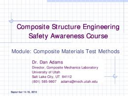
MIL-HDBK-17
MATRIX MATERIAL CHARACTERIZATION
INTERPHASE MATERIAL CHARACTERIZATION
FIBER CHARACTERIZATION
PREPREG EVALUATION
LAMINA/LAMINATE CHARACTERIZATION
NOTCHED/DAMAGED LAMINATE EVALUATION
JOINT EVALUATION
DETERMINATION OF STRUCTURAL DESIGN VALUES CERTIFICATION OF THE COMPOSITE STRUCTURE FIGURE 1.1 Focus of MIL-HDBK-17 indicated by shaded block.
5
MIL-HDBK-17-5 Volume 5, Part A Introduction and Guidelines
1.3 SCOPE For Department of Defense purposes, this handbook is for guidance only. This handbook cannot be cited as a requirement. If it is, the contractor does not have to comply. This mandate is a DoD requirement only; it is not applicable to the Federal Aviation Administration (FAA) or other government agencies. The four parts of MIL-HDBK-17, Volume 5, serve as a general Reference source for technical information on ceramic matrix composites, including: 1.3.1 Part A: Introduction and Guidelines This part contains guidelines for determining the properties of composite material systems, their constituents, and generic structural elements, including test planning, test matrices, sampling, conditioning, test procedure selection, data reporting, data reduction, statistical analysis, and other related topics. Part A contains guidelines for general development of material characterization data as well as specific requirements for publication of material data in MIL-HDBK-17. It must be emphasized that this handbook differentiates between material basis values (material allowables) and design allowable values. Material basis values, being an intrinsic property of a composite material system, are the focus of this handbook. Design allowable values, while often rooted in material basis values, are application dependent, and include specific additional considerations that may further affect the strength or stiffness of the structure. Also, when establishing application design values there may be additional certification or procurement agency requirements that go beyond MIL-HDBK-17. 1.3.2 Part B: Design Supportability Part B provides methodologies and lessons learned for the design, manufacture, analysis, and supportability of composite structures, and for utilization of the material data provided in Part D consistent with the guidance provided in Part A. Topics discussed in Part B include materials and processing, quality control, design and analysis, joints, reliability, thick composites, and supportability. 1.3.3 Part C: Testing Part C addresses issues related to test methods and requirements for submission of data to MIL-17. 1.3.4 Part D: Data Requirements and Data Sets Part D contains statistically-based data meeting specific MIL-HDBK-17 population sampling and data documentation requirements, covering constituents and material systems of general interest. Data published in Part D are under the jurisdiction of the Data Review Working Group and are approved by the overall Coordination Group (The MIL-HDBK-17 Coordination Group and Working Groups are discussed in Section 1.1). New material systems will be included and additional material data for existing systems will be added as approved data becomes available. The material properties in Part D are defined over a range of potential use conditions, focusing, when possible, on the upper and lower material environmental limits so that application-specific environments do not limit use of the data. Special attention is given to the statistical treatment and analysis of data. Data at intermediate environmental conditions, when available, provide additional definition of the relation between material response and environment. While the process of establishing structural design values for specific applications can begin with the data contained in Part D, most applications require collection of additional data, especially if there are requirements for data from the laminate or higher structural complexity levels. Also, the ability to manufacture material equivalent to that from which the data in Part D were obtained typically must be proven to the procuring or certifying agency, which usually involves limited testing and data comparison. General
6
MIL-HDBK-17-5 Volume 5, Part A Introduction and Guidelines guidelines for such material/process equivalence evaluation are presented in Part A; however, many of the details of such an evaluation remain at the discretion of the procuring or certifying agency.
1.4 USE OF THE DOCUMENT AND LIMITATIONS 1.4.1 Source of information The information contained in MIL-HDBK-17 is obtained from materials producers and fabricators, the aerospace industry, reports on government-sponsored research, open literature, direct contacts with researchers, and from participants in MIL-HDBK-17 coordination activities. All information published in this document has been coordinated and reviewed by representatives from industry, the US Army, the US Air Force, US Navy, the US Federal Aviation Administration, the Department of Energy, and NASA. Every effort has been made to reflect the most up-to-date information on the use of composite materials, with particular emphasis on use of composites in structures. The handbook is continually reviewed and revised to keep current with the state-of-the-art in order to ensure completeness and accuracy. 1.4.2 Use of data and guidelines in applications All data contained herein are based on small-scale test specimens, predominantly loaded quasi1 statically and uniaxially, for specific environmental conditions. It is the user's responsibility to determine if handbook data are appropriate for a given application and to translate or scale the data as necessary for use: • • • • •
in a multi-directional laminate, on a structure of different characteristic size and geometry, under a multi-directional stress state, when exposed to a different environment, and/or when subjected to non-static loading.
Further discussions of these and other issues are provided in Part D. Specific uses of handbook data are beyond the scope and responsibility of MIL-HDBK-17, and applicability and interpretation of specific provisions of this handbook may require approval by an appropriate procurement or certification agency. 1.4.3 Strength properties and allowables terminology The handbook intent is to provide guidelines for generating material property data, including statistically-based strength data at environmental extremes that bracket most intermediate application-specific environments. The philosophy is to avoid having application-specific issues govern generic material property characterization programs. If data are also available at intermediate environmental conditions, they can be used to more completely define the relationship between the property and the effect of the environment on that property. However, in some cases an environmental limit for a composite material system may be application dependent, and in others, data at environmental limits may not be available. Available statistically-based strength data are tabulated in Part D. These data are useful as a starting point for establishing structural design allowable values when stress and strength analysis capabilities permit lamina-level margin-of-safety calculations. For such cases the MIL-HDBK-17 strength basis value may also be termed a material design allowable. Depending on the application, some structural design allowables may have to be empirically determined from additional laminate, element, or higher-level test data not provided by MIL-HDBK-17. 1 Unless otherwise noted, tests were conducted in conformance with the particular test method noted. The emphasis is on data obtained from ASTM standard test methods for advanced composites, but where an ASTM test method has been deemed inappropriate or is not yet available, or when data from a nonstandard but commonly practiced test procedure are available, then data from a non-standard test method may have been accepted for publication. The specific test method used is noted in the data documentation. See also the statement on test method acceptance criteria in Volume 1, Section 2.5.5.
7
MIL-HDBK-17-5 Volume 5, Part A Introduction and Guidelines
1.4.4 Use of References While many References are provided at the end of each chapter, note that the information in these citations may not necessarily comply in every respect either with the general guidelines for data development or with the specific requirements for publication of data in the handbook. The References are simply intended to be helpful, but not necessarily complete or authoritative sources of additional related information on specific subject areas. 1.4.5 Use of tradenames and product names Use of tradenames or proprietary product names does not constitute an endorsement of those products by the US Government or by the MIL-HDBK-17 Coordination Group. 1.4.6 Toxicity, health hazards, and safety Certain processing and test methods discussed in MIL-HDBK-17 may involve hazardous materials, operations, or equipment. These methods may not address safety problems, if any, associated with their use. It is the responsibility of the user of these methods to establish appropriate safety and health practices and to determine the applicability of regulatory limitations prior to use. The user is referred to the Advanced Composite Materials US Army Interim Health and Safety Guidance for a discussion of the health and safety issues involved in the processing and use of composite materials. This document is generated by the US Army Environmental Hygiene Agency, Aberdeen Proving Ground, MD. Material manufacturers, as well as various composites user groups, may also provide guidance on health and safety issues pertinent to composite materials. 1.4.7 Ozone depleting chemicals Restrictions on the use of ozone depleting chemicals are detailed in the US Clean Air Act of 1991.
1.5 APPROVAL PROCEDURES The content of the handbook is developed and approved by the MIL-HDBK-17 Coordination Group as shown in Figure 1.5, which meets every eight months to consider changes and additions to the handbook. This Group consists of the handbook Co-Chairs, Coordinator, Secretariat, Working Group Chairs, and the active Working Group participants, which include representatives from various US and international procuring and certifying agencies, in addition to the producing industries and academic and research institutions. MIL-HDBK-17 Coordination Group meetings are announced to participants by mail about eight weeks prior to the scheduled meeting date, and minutes of the meetings are mailed eight weeks following the close of the meeting. While each of the Working Groups functions similarly, they are of two types: Executive, a single Working Group with oversight responsibility composed of the Working Group Chairs, the handbook Co-Chairs, Coordinator, and Secretariat; and Standing, including Data Review, Materials and Processing, Structural Analysis and Design, and Testing Working Groups. The makeup and organization of the Coordination Group and Working Groups, as well as the procedures followed for document change approval, are summarized in the MIL-HDBK-17 Coordination Group Member's Guide, separately published and available from either the Coordinator or Secretariat. Proposals for addition to, deletion from, or modification to the handbook should be submitted to both the appropriate Working Group and the Secretariat well in advance of the announcement mailing date, and should include specific notation of the proposed changes and adequate documentation of supporting data or analytical procedures. Reproducible copies of figures, drawings, or photographs proposed for publication in the document should be furnished to the Secretariat. Following approval by the appropriate Working Group, the proposed changes are published in the next minutes of the Coordination Group, in a 8
MIL-HDBK-17-5 Volume 5, Part A Introduction and Guidelines special section of the minutes called the "yellow pages", and all participants are allowed comment on the proposed changes. If no substantive comments are received on any individual item by the posted response date, then that item is considered approved by the Coordination Group and is considered effective as of that date. (Prior to publication in the next revision of the handbook the collected changes are reviewed by various branches of the US DoD. Additional proposals for revision may result from this US DoD review.) Requests for inclusion of material property data into MIL-HDBK-17 should be submitted to either the Coordinator or the Secretariat, accompanied by the documentation specified in Part D, Chapter 17. A Data Source Information Package has been created to aid those considering submitting data for inclusion in MIL-HDBK-17, and is available from either the Coordinator or the Secretariat. The Secretariat reviews and analyzes each data submission and, at the next available meeting of the Coordination Group, presents a summary for evaluation by the Data Review Working Group. The choice of new materials to be included herein is governed by the MIL-HDBK-17 Coordination Group. Practical considerations preclude inclusion of all advanced composite materials, but reasonable attempts will be made to add new material systems of interest in a timely manner.
WORKING GROUP REVIEW/APPROVAL 1 or more cycles COORDINATION GROUP REVIEW/APPROVAL "Yellow pages" COMMENTS/CRITICISM separated by Secretariat with Chair concurrence Minor editorial Secretariat
Major editorial/minor technical WG chair, HDBK chair, author, commenter agreement
Major technical Returned to WG
Incorporated into Handbook DOD COORDINATION REVIEW comment cycle PUBLICATION Official Release
FIGURE 1.5 Approval Procedures
1.6 SYMBOLS, ABBREVIATIONS, AND SYSTEMS OF UNITS This section defines the symbols and abbreviations which are used within MIL-HDBK-17 and describes the system of units which is maintained. Common usage is maintained where possible. References 1.6(a), 1.6(b), and 1.6(c) served as primary sources for this information.
9
MIL-HDBK-17-5 Volume 5, Part A Introduction and Guidelines 1.6.1 Symbols and abbreviations The symbols and abbreviations used in this document are defined in this section with the exception of statistical symbols. These latter symbols are defined in Part C, Section 16.1.3. The lamina/laminate coordinate axes used for all properties and a summary of the mechanical property notation are shown in Figure 1.6.1. •
The symbols f and m, when used as either subscripts or superscripts, always denote fiber and matrix, respectively.
•
The type of stress (for example, cy - compressive yield) is always used in the superscript position.
•
Direction indicators (for example, x, y, z, 1, 2, 3, etc.) are always used in the subscript position.
•
Ordinal indicators of laminae sequence (e.g., 1, 2, 3, etc.) are used in the superscript position and must be parenthesized to distinguish them from mathematical exponents.
•
Other indicators may be used in either subscript or superscript position, as appropriate for clarity.
•
Compound symbols (such as, basic symbols plus indicators) which deviate from these rules are shown in their specific form in the following list.
The following general symbols and abbreviations are considered standard for use in MIL-HDBK-17. Where exceptions are made, they are noted in the text and tables. A
a
B Btu b C CF CPF CPT CG
C L c c cpm D
d
-
2
2
-
(1) area (m ,in ) (2) ratio of alternating stress to mean stress (3) A-basis for mechanical property values (1) length dimension (mm,in) 2 2 (2) acceleration (m/sec ,ft/sec ) (3) amplitude (4) crack or flaw dimension (mm,in) (1) B-basis for mechanical property values (2) biaxial ratio British thermal unit(s) width dimension (mm,in), e.g., the width of a bearing or compression panel normal to load, or breadth of beam cross-section (1) specific heat (kJ/kg °C,Btu/lb °F) (2) Celsius centrifugal force (N,lbf) crossply factor cured ply thickness (mm, in.) (1) center of mass, "center of gravity" (2) area or volume centroid centerline
-
column buckling end-fixity coefficient honeycomb sandwich core depth (mm,in) cycles per minute (1) diameter (mm,in) (2) hole or fastener diameter (mm,in) (3) plate stiffness (N-m,lbf-in) mathematical operator denoting differential
10
MIL-HDBK-17-5 Volume 5, Part A Introduction and Guidelines
FIGURE 1.6.1 Mechanical property notation.
11
MIL-HDBK-17-5 Volume 5, Part A Introduction and Guidelines
E
-
E' E" Ec
-
E’c Esec Etan e e/D F
-
Fb Fccr Fsu FAW FV f fc fc ft G GPa g
H/C h hr I i in. J K
Kapp Kc KIc KN Ks Kt Kv Kx,Ky k
-
modulus of elasticity in tension, average ratio of stress to strain for stress below proportional limit (GPa,Msi) storage modulus (GPa,Msi) loss modulus (GPa,Msi) modulus of elasticity in compression, average ratio of stress to strain for stress below proportional limit (GPa,Msi) modulus of elasticity of honeycomb core normal to sandwich plane (GPa,Msi) secant modulus (GPa,Msi) tangent modulus (GPa,Msi) minimum distance from a hole center to the edge of the sheet (mm,in) ratio of edge distance to hole diameter (bearing strength) (1) stress (MPa,ksi) (2) Fahrenheit bending stress (MPa,ksi) crushing or crippling stress (upper limit of column stress for failure) (MPa,ksi) ultimate stress in pure shear (this value represents the average shear stress over the cross-section) (MPa,ksi) 2 2 fiber areal weight (g/m , lb/in ) fiber volume (%) (1) internal (or calculated) stress (MPa,ksi) (2) stress applied to the gross flawed section (MPa,ksi) (3) creep stress (MPa,ksi) internal (or calculated) compressive stress (MPa,ksi) (1) maximum stress at fracture (MPa,ksi) (2) gross stress limit (for screening elastic fracture data (MPa,ksi) foot, feet modulus of rigidity (shear modulus) (GPa,Msi) gigapascal(s) (1) gram(s) 2 2 (2) acceleration due to gravity (m/s ,ft/s ) honeycomb (sandwich) height dimension (mm,in) e.g., the height of a beam cross-section hour(s) 4 4 area moment of inertia (mm ,in ) slope (due to bending) of neutral plane in a beam, in radians inch(es) 4 4 (1) torsion constant (= Ip for round tubes) (m ,in ) (2) Joule (1) Kelvin (2) stress intensity factor (MPa/m,ksi/in) 2 (3) coefficient of thermal conductivity (W/m °C, Btu/ft /hr/in/°F) (4) correction factor (5) dielectric constant apparent plane strain fracture toughness or residual strength (MPa/m,ksi/in) critical plane strain fracture toughness, a measure of fracture toughness at point of crack growth instability (MPa/m,ksi/in) plane strain fracture toughness (MPa/m,ksi/in) empirically calculated fatigue notch factor plate or cylinder shear buckling coefficient (1) theoretical elastic stress concentration factor (2) tw/c ratio in H/C sandwich dielectric strength (KV/mm, V/mil) plate or cylinder compressive buckling coefficient strain at unit stress (m/m,in/in) 12
MIL-HDBK-17-5 Volume 5, Part A Introduction and Guidelines
L L' lb M Mg MPa m
N
NA n
P
Pf Pu Py p psi Q q R r
S
Sa Se Sm Smax Smin SR S.F. s T Td TF Tg Tm
-
cylinder, beam, or column length (mm,in) effective column length (mm,in) pound applied moment or couple (N-m,in-lbf) megagram(s) megapascal(s) (1) mass (kg,lb) (2) number of half wave lengths (3) metre (4) slope (1) number of fatigue cycles to failure (2) number of laminae in a laminate (3) distributed in-plane forces on a panel (lbf/in) (4) Newton (5) normalized neutral axis (1) number of times in a set (2) number of half or total wavelengths (3) number of fatigue cycles endured (1) applied load (N,lbf) (2) exposure parameter (3) probability (4) specific resistance (Ω) failure load test ultimate load, (N,lb per fastener) test yield load, (N,lb per fastener) normal pressure (Pa,psi) pounds per square inch 3 3 area static moment of a cross-section (mm ,in ) shear flow (N/m,lbf/in) (1) algebraic ratio of minimum load to maximum load in cyclic loading (2) reduced ratio (1) radius (mm,in) (2) root radius (mm,in) (3) reduced ratio (regression analysis) (1) shear force (N,lbf) (2) nominal stress in fatigue (MPa,ksi) (3) S-basis for mechanical property values stress amplitude in fatigue (MPa,ksi) fatigue limit (MPa,ksi) mean stress in fatigue (MPa,ksi) highest algebraic value of stress in the stress cycle (MPa,ksi) lowest algebraic value of stress in the stress cycle (MPa,ksi) algebraic difference between the minimum and maximum stresses in one cycle (MPa,ksi) safety factor (1) arc length (mm,in) (2) H/C sandwich cell size (mm,in) (1) temperature (°C,°F) (2) applied torsional moment (N-m,in-lbf) thermal decomposition temperature (°C,°F) exposure temperature (°C,°F) glass transition temperature (°C,°F) melting temperature (°C,°F)
13
MIL-HDBK-17-5 Volume 5, Part A Introduction and Guidelines -
(1) thickness (mm,in) (2) exposure time (s) (3) elapsed time (s) 3 3 (1) volume (mm ,in ) (2) shear force (N,lbf) (1) weight (N,lbf) (2) width (mm,in) (3) Watt distance along a coordinate axis nondimensional factor relating component geometry and flaw size (1) deflection (due to bending) of elastic curve of a beam (mm,in) (2) distance from neutral axis to given point (3) distance along a coordinate axis 3 3 section modulus, I/y (mm ,in ) coefficient of thermal expansion (m/m/°C,in/in/°F) shear strain (m/m,in/in)
-
difference (used as prefix to quantitative symbols) elongation or deflection (mm,in) strain (m/m,in/in) elastic strain (m/m,in/in) plastic strain (m/m,in/in) permeability plasticity reduction factor intrinsic viscosity dynamic complex viscosity Poisson's ratio 3 3 (1) density (kg/m ,lb/in ) (2) radius of gyration (mm,in)
ρ’c
-
H/C sandwich core density (kg/m ,lb/in )
Σ σ σij, τ
-
total, summation standard deviation stress in j direction on surface whose outer normal is in i direction (i, j = 1, 2, 3 or x, y, z) (MPa,ksi) applied shear stress (MPa,ksi) angular velocity (radians/s) infinity
t
V W
x Y y
Z
α γ
∆ δ ε εe εp µ η [η] η*
ν
ρ
Τ ω
∞
ij
-
3
3
1.6.1.1 Constituent properties The following symbols apply specifically to the constituent properties of a typical composite material.
Ef Em Egx
-
Egy
-
Young's modulus of filament material (MPa,ksi) Young's modulus of matrix material (MPa,ksi) Young's modulus of impregnated glass scrim cloth in the filament direction or in the warp direction of a fabric (MPa,ksi) Young's modulus of impregnated glass scrim cloth transverse to the filament direction
Gf Gm G gxy
-
or to the warp direction in a fabric (MPa,ksi) shear modulus of filament material (MPa,ksi) shear modulus of matrix (MPa,ksi) shear modulus of impregnated glass scrim cloth (MPa,ksi)
G’cx
-
shear modulus of sandwich core along X-axis (MPa,ksi)
14
MIL-HDBK-17-5 Volume 5, Part A Introduction and Guidelines
G’cy
-
shear modulus of sandwich core along Y-axis (MPa,ksi)
α α
-
filament length (mm,in) coefficient of thermal expansion for filament material (m/m/°C,in/in/°F) coefficient of thermal expansion for matrix material (m/m/°C,in/in/°F)
α gx
-
α gy
-
coefficient of thermal expansion of impregnated glass scrim cloth in the filament direction or in the warp direction of a fabric (m/m/°C,in/in/°F) coefficient of thermal expansion of impregnated glass scrim cloth transverse to the
νf νm
-
filament direction or to the warp direction in a fabric (m/m/°C,in/in/°F) Poisson's ratio of filament material Poisson's ratio of matrix material
ν gxy
-
glass scrim cloth Poisson's ratio relating to contraction in the transverse (or fill) direc-
ν gyx
-
tion as a result of extension in the longitudinal (or warp) direction glass scrim cloth Poisson's ratio relating to contraction in the longitudinal (or warp) di-
-
rection as a result of extension in the transverse (or fill) direction applied axial stress at a point, as used in micromechanics analysis (MPa,ksi) applied shear stress at a point, as used in micromechanics analysis (MPa,ksi)
f m
σ
τ
1.6.1.2 Laminae and laminates The following symbols, abbreviations, and notations apply to composite laminae and laminates. At the present time the focus in MIL-HDBK-17 is on laminae properties. However, commonly used nomenclature for both laminae and laminates are included here to avoid potential confusion.
Aij (i,j = 1,2,6) Bij (i,j = 1,2,6) Cij (i,j = 1,2,6) Dx, Dy Dxy Dij (i,j = 1,2,6) E1 E2 Ex Ey G12 Gxy hi Mx, My, Mxy
-
nf Qx, Qy
-
Qij (i,j = 1,2,6) ux, uy, uz uox , uoy , uoz
-
extensional rigidities (N/m,lbf/in) coupling matrix (N,lbf) elements of stiffness matrix (Pa,psi) flexural rigidities (N-m,lbf-in) twisting rigidity (N-m,lbf-in) flexural rigidities (N-m,lbf-in) Young's modulus of lamina parallel to filament or warp direction (GPa,Msi) Young's modulus of lamina transverse to filament or warp direction (GPa,Msi) Young's modulus of laminate along x Reference axis (GPa,Msi) Young's modulus of laminate along y Reference axis (GPa,Msi) shear modulus of lamina in 12 plane (GPa,Msi) shear modulus of laminate in xy Reference plane (GPa,Msi) thickness of ith ply or lamina (mm,in) bending and twisting moment components (N-m/m, in-lbf/in in plate and shell analysis) number of filaments per unit length per lamina shear force parallel to z axis of sections of a plate perpendicular to x and y axes, respectively (N/m,lbf/in) reduced stiffness matrix (Pa,psi) components of the displacement vector (mm,in) components of the displacement vector at the laminate's midsurface (mm,in)
Vv Vf Vg Vm Vx, Vy Wf Wg Wm
-
void content (% by volume) filament content or fiber volume (% by volume) glass scrim cloth content (% by volume) matrix content (% by volume) edge or support shear force (N/m,lbf/in) filament content (% by weight) glass scrim cloth content (% by weight) matrix content (% by weight) 15
MIL-HDBK-17-5 Volume 5, Part A Introduction and Guidelines
x
-
α
y
-
α
xy
2
2
θ
-
λ xy ν 12
-
ν 21
-
ν xy
-
ν yx
-
ρc
-
weight of laminate per unit surface area (N/m ,lbf/in ) lamina coefficient of thermal expansion along 1 axis (m/m/°C,in/in/°F) lamina coefficient of thermal expansion along 2 axis (m/m/°C,in/in/°F) laminate coefficient of thermal expansion along general Reference x axis (m/m/°C, in/in/°F) laminate coefficient of thermal expansion along general Reference y axis (m/m/°C, in/in/°F) laminate shear distortion coefficient of thermal expansion (m/m/°C,in/in/°F) angular orientation of a lamina in a laminate, i.e., angle between 1 and x axes (°) product of ν xy and ν yx Poisson's ratio relating contraction in the 2 direction as a result of extension in 1 the 1 direction Poisson's ratio relating contraction in the 1 direction as a result of extension in 1 the 2 direction Poisson's ratio relating contraction in the y direction as a result of extension in 1 the x direction Poisson's ratio relating contraction in the x direction as a result of extension in 1 the y direction 3 3 density of a single lamina (kg/m ,lb/in )
ρc
-
density of a laminate (kg/m ,lb/in )
φ
-
(1) general angular coordinate, (°) (2) angle between x and load axes in off-axis loading (°)
Ws
α α α
1 2
3
3
1.6.1.3 Subscripts The following subscript notations are considered standard in MIL-HDBK-17.
1, 2, 3 A a app byp c
cf e eff eq f g H i L m max min n
-
-
laminae natural orthogonal coordinates (1 is filament or warp direction) axial (1) adhesive (2) alternating apparent bypass composite system, specific filament/matrix composition. Composite as a whole, contrasted to individual constituents. Also, sandwich core when used in conjunction with prime (') (4) critical centrifugal force fatigue or endurance effective equivalent filament glass scrim cloth hoop ith position in a sequence lateral (1) matrix (2) mean maximum minimum (1) nth (last) position in a sequence
1
The convention for Poisson’s ratio should be checked before comparing different sources as different conventions are used.
16
MIL-HDBK-17-5 Volume 5, Part A Introduction and Guidelines
p s st T t x, y, z ∑ o ()
-
(2) normal polar symmetric stiffener transverse value of parameter at time t general coordinate system total, or summation initial or Reference datum format for indicating specific, temperature associated with term in parentheses. RT room temperature (21°C,70°F); all other temperatures in °F unless specified.
1.6.1.4 Superscripts The following superscript notations are considered standard in MIL-HDBK-17.
b br c cc cr e f g is (i) lim m ohc oht p pl rup s scr sec so T t tan u y ' CAI
-
bending bearing (1) compression (2) creep compressive crippling compressive buckling elastic filament glass scrim cloth interlaminar shear th i ply or lamina limit, used to indicate limit loading matrix open hole compression open hole tension plastic proportional limit rupture shear shear buckling secant (modulus) offset shear temperature or thermal tension tangent (modulus) ultimate yield secondary (modulus), or denotes properties of H/C core when used with subscript c compression after impact
1.6.1.5 Acronyms The following acronyms are used in MIL-HDBK-17. AA ACUT AES AIA ANL ANOVA
-
atomic absorption air coupled ultrasonic testing system Auger electron spectroscopy Aerospace Industries Association Argonne National Laboratory analysis of variance 17
MIL-HDBK-17-5 Volume 5, Part A Introduction and Guidelines ARL ASNT ASTM BMI BVID CA CAI CAT CCA CFCC CLS CPT CTA CTD CTE CV CVD CVI DCB DDA DLL DMA DoD DoE DSC DT DTA ECT ENF EOL ESCA ESR ETW FAA FAW FFF FM FMECA FOD FTIR FWC GC GSCS HAW HDT HPLC ICP ID IR ISI ISS JANNAF LA LC LCF LC
-
US Army Research Laboratory American Society of Nondestructive Testing American Society for Testing and Materials bismaleimide barely visible impact damage commercially available compression after impact computer aided tomography composite cylinder assemblage continuous fiber ceramic composite crack lap shear cured ply thickness cold temperature ambient cold temperature dry coefficient of thermal expansion coefficient of variation chemical vapor deposition chemical vapor infiltration double cantilever beam dynamic dielectric analysis design limit load dynamic mechanical analysis Department of Defense Department of Energy differential scanning calorimetry dye penetrant testing differential thermal analysis eddy current testing end notched flexure end-of-life electron spectroscopy for chemical analysis electron spin resonance elevated temperature wet Federal Aviation Administration fiber aerial weight field flow fractionation fibrous monolith Failure Modes Effects Criticality Analysis foreign object damage Fourier transform infrared spectroscopy finite width correction factor gas chromatography Generalized Self Consistent Scheme hypersonic aerodynamic weapons heat distortion temperature high performance liquid chromatography inductively coupled plasma emission spectroscopy identification infrared in-service inspection ion scattering spectroscopy Joint Army, Navy, NASA, and Air Force limited availability liquid chromatography low cycle fatigue liquid chromatography 18
MIL-HDBK-17-5 Volume 5, Part A Introduction and Guidelines LPT LSS MI MMB MOL MPIT MS M.S. MSDS MTBF MW MWD NAS NASA NDC NDE NDI NDT NMR OSL P PC PP PEEK PT RA RBSN RDS RGT RH RMS RT RTA RTD RTM RV SACMA SBS SAE SANS SEC SEM SFC SI SIMS TBA TEM TGA TLC TMA TOS TVM UDC UT VNB
-
laminate plate theory laminate stacking sequence melt infiltration mixed mode bending material operational limit magnetic particle testing (1) mass spectroscopy (2) military standard margin of safety material safety data sheet Mean Time Between Failure molecular weight molecular weight distribution National Aerospace Standard National Aeronautics and Space Administration nondestructive characterization nondestructive evaluation nondestructive inspection nondestructive testing nuclear magnetic resonance observed significance level prototype pyrolytic carbon polymer pyrolysis polyether ether ketone dye penetrate testing reduction of area reaction bonded silicon nitride rheological dynamic spectroscopy radiographic testing relative humidity root-mean-square room temperature room temperature ambient room temperature dry resin transfer molding reentry vehicle Suppliers of Advanced Composite Materials Association short beam shear strength Society of Automotive Engineers small-angle neutron scattering spectroscopy size-exclusion chromatography scanning electron microscopy supercritical fluid chromatography International System of Units (Le Système International d'Unités) secondary ion mass spectroscopy torsional braid analysis transmission electron microscopy thermogravimetric analysis thin-layer chromatography thermal mechanical analysis thermal oxidative stability transverse microcrack unidirectional fiber composite ultrasonic testing V-notched beam 19
MIL-HDBK-17-5 Volume 5, Part A Introduction and Guidelines WoF XCT XD XPS
-
work of fracture X-ray computed tomography experimental development X-ray photoelectron spectroscopy
1.6.2 System of units To comply with Department of Defense Instructive 5000.2, Part 6, Section M, "Use of the Metric System," dated February 23, 1991, the data in MIL-HDBK-17 are generally presented in both the International System of Units (SI units) and the U. S. Customary (English) system of units. ASTM E-380, Standard for Metric Practice, provides guidance for the application for SI units which are intended as a basis for worldwide standardization of measurement units (Reference 1.6.2(a)). Further guidelines on the use of the SI system of units and conversion factors are contained in the following publications (References 1.6.2(b) (e)): (1) DARCOM P 706-470, Engineering Design Handbook: Metric Conversion Guide, July 1976. (2) NBS Special Publication 330, "The International System of Units (SI)," National Bureau of Standards, 1986 edition. (3) NBS Letter Circular LC 1035, "Units and Systems of Weights and Measures, Their Origin, Development, and Present Status," National Bureau of Standards, November 1985. (4) NASA Special Publication 7012, "The International System of Units Physical Constants and Conversion Factors", 1964. English to SI conversion factors pertinent to MIL-HDBK-17 data are contained in Table 1.6.2.
1.7 DEFINITIONS The following definitions are used within MIL-HDBK-17. This glossary of terms is not totally comprehensive but it does represent nearly all commonly used terms. Where exceptions are made, they are noted in the text and Tables. For ease of identification the definitions have been organized alphabetically. A-Basis (or A-Value) -- A statistically-based material property; a 95% lower confidence bound on the first percentile of a specified population of measurements. Also a 95% lower tolerance bound for the upper 99% of a specified population. A-Stage -- An early stage in the reaction of thermosetting resins in which the material is still soluble in certain liquids and may be liquid or capable of becoming liquid upon heating. (Sometimes referred to as resol.) Absorption -- A process in which one material (the absorbent) takes in or absorbs another (the absorbate). Accuracy -- The degree of conformity of a measured or calculated value to some recognized standard or specified value. Accuracy involves the systematic error of an operation. Adhesion -- The state in which two surfaces are held together at an interface by forces or interlocking action or both. Adhesive -- A substance capable of holding two materials together by surface attachment. In the handbook, the term is used specifically to designate structural adhesives, those which produce attachments capable of transmitting significant structural loads.
20
MIL-HDBK-17-5 Volume 5, Part A Introduction and Guidelines
TABLE 1.6.2 English to SI conversion factors. ___________________________________________________________________________ To convert from to Multiplied by ___________________________________________________________________________ 2
2
2
Btu (thermochemical)/in -s watt/meter (W/m ) 1.634 246 E+06 2 Btu-in/(s-ft -°F) W/(m K) 5.192 204 E+02 degree Fahrenheit degree Celsius (°C) T = (T - 32)/1.8 degree Fahrenheit kelvin (K) T = (T + 459.67)/1.8 foot meter (m) 3.048 000 E-01 2 2 ft m 9.290 304 E-02 foot/second meter/second (m/s) 3.048 000 E-01 2 2 ft/s m/s 3.048 000 E-01 inch meter (m) 2.540 000 E-02 2 2 2 in. meter (m ) 6.451 600 E-04 3 3 m 1.638 706 E-05 in. kilogram-force (kgf) newton (N) 9.806 650 E+00 2 kgf/m pascal (Pa) 9.806 650 E+00 kip (1000 lbf) newton (N) 4.448 222 E+03 2 ksi (kip/in ) MPa 6.894 757 E+00 lbf-in N-m 1.129 848 E-01 lbf-ft N-m 1.355 818 E+00 2 lbf/in (psi) pascal (Pa) 6.894 757 E+03 2 2 lb/in gm/m 7.030 696 E+05 3 3 lb/in kg/m 2.767 990 E+04 6 Msi (10 psi) GPa 6.894 757 E+00 pound-force (lbf) newton (N) 4.488 222 E+00 pound-mass (lb avoirdupois) kilogram (kg) 4.535 924 E-01 torr pascal (Pa) 1.333 22 E+02 ___________________________________________________________________________ ∗
The letter "E" following the conversion factor stands for exponent and the two digits after the letter "E" indicate the power of 10 by which the number is to be multiplied.
ADK -- Notation used for the k-sample Anderson-Darling statistic, which is used to test the hypothesis that k batches have the same distribution. Aliquot -- A small, representative portion of a larger sample. Aging -- The effect, on materials, of exposure to an environment for a period of time; the process of exposing materials to an environment for an interval of time. Ambient -- The surrounding environmental conditions such as pressure or temperature. Anelasticity -- A characteristic exhibited by certain materials in which strain is a function of both stress and time, such that, while no permanent deformations are involved, a finite time is required to establish equilibrium between stress and strain in both the loading and unloading directions. Angleply -- Same as Crossply.
21
MIL-HDBK-17-5 Volume 5, Part A Introduction and Guidelines Anisotropic -- Not isotropic; having mechanical and/or physical properties which vary with direction relative to natural Reference axes inherent in the material. Areal Weight of Fiber -- The weight of fiber per unit area of prepreg. This is often expressed as grams per square meter. See Table 1.6.2 for conversion factors. Artificial Weathering -- Exposure to laboratory conditions which may be cyclic, involving changes in temperature, relative humidity, radiant energy and any other elements found in the atmosphere in various geographical areas. Aspect Ratio -- In an essentially two-dimensional rectangular structure (e.g., a panel), the ratio of the long dimension to the short dimension. However, in compression loading, it is sometimes considered to be the ratio of the load direction dimension to the transverse dimension. Also, in fiber micro-mechanics, it is referred to as the ratio of length to diameter. Autoclave -- A closed vessel for producing an environment of fluid pressure, with or without heat, to an enclosed object which is undergoing a chemical reaction or other operation. Autoclave Molding -- A process similar to the pressure bag technique. The lay-up is covered by a pressure bag, and the entire assembly is placed in an autoclave capable of providing heat and pressure for curing the part. The pressure bag is normally vented to the outside. Axis of Braiding -- The direction in which the braided form progresses. B-Basis (or B-Value) -- A statistically-based material property; a 95% lower confidence bound on the tenth percentile of a specified population of measurements. Also a 95% lower tolerance bound for the upper 90% of a specified population. (See Volume 1, Section 8.1.4) B-Stage -- An intermediate stage in the reaction of a thermosetting resin in which the material softens when heated and swells when in contact with certain liquids but does not entirely fuse or dissolve. Materials are usually precured to this stage to facilitate handling and processing prior to final cure. (Sometimes referred to as resitol.) Balanced Laminate -- A composite laminate in which all laminae at angles other than 0 degrees and 90 degrees occur only in ± pairs (not necessarily adjacent). Batch (or Lot) -- For fibers and resins, a quantity of material formed during the same process and having identical characteristics throughout. For prepregs, laminae, and laminates, material made from one batch of fiber and one batch of resin. Bearing Area -- The product of the pin diameter and the specimen thickness. Bearing Load -- A compressive load on an interface. Bearing Yield Strength -- The bearing stress at which a material exhibits a specified limiting deviation from the proportionality of bearing stress to bearing strain. Bend Test -- A test of ductility by bending or folding, usually with steadily applied forces. In some instances the test may involve blows to a specimen having a cross section that is essentially uniform over a length several times as great as the largest dimension of the cross section. Bias -The orientation that is oblique to the warp direction. Binder -- A bonding resin used to hold strands together in a mat or preform during manufacture of a molded object.
22
MIL-HDBK-17-5 Volume 5, Part A Introduction and Guidelines Binomial Random Variable -- The number of successes in independent trials where the probability of success is the same for each trial. Birefringence -- The difference between the two principal refractive indices (of a fiber) or the ratio between the retardation and thickness of a material at a given point. Bleeder Cloth -- A nonstructural layer of material used in the manufacture of composite parts to allow the escape of excess gas and resin during cure. The bleeder cloth is removed after the curing process and is not part of the final composite. Bobbin -- A cylinder or slightly tapered barrel, with or without flanges, for holding tows, rovings, or yarns. Bond -- The adhesion of one surface to another, with or without the use of an adhesive as a bonding agent. Braid -- A system of three or more yarns which are interwoven in such a way that no two yarns are twisted around each other. Braid Angle -- The acute angle measured from the axis of braiding. Braid, Biaxial -- Braided fabric with two-yarn systems, one running in the +θ direction, the other in the -θ direction as measured from the axis of braiding. Braid Count -- The number of braiding yarn crossings per inch measured along the axis of a braided fabric. Braid, Diamond -- Braided fabric with an over one, under one weave pattern, (1 x 1). Braid, Flat -- A narrow bias woven tape wherein each yarn is continuous and is intertwined with every other yarn in the system without being intertwined with itself. Braid, Hercules -- A braided fabric with an over three, under three weave pattern, (3 x 3). Braid, Jacquard -- A braided design made with the aid of a jacquard machine, which is a shedding mechanism by means of which a large number of ends may be controlled independently and complicated patterns produced. Braid, Regular -- A braided fabric with an over two, under two weave pattern (2 x 2). Braid, Square -- A braided pattern in which the yarns are formed into a square pattern. Braid, Two-Dimensional -- Braided fabric with no braiding yarns in the through thickness direction. Braid, Three-Dimensional -- Braided fabric with one or more braiding yarns in the through thickness direction. Braid, Triaxial -- A biaxial braided fabric with laid in yarns running in the axis of braiding. Braiding -- A textile process where two or more strands, yarns or tapes are intertwined in the bias direction to form an integrated structure. Braze – To join using a filler material which melts at a lower temperature than either of the materials being joined.
23
MIL-HDBK-17-5 Volume 5, Part A Introduction and Guidelines Broadgoods -- A term loosely applied to prepreg material greater than about 12 inches in width, usually furnished by suppliers in continuous rolls. The term is currently used to designate both collimated uniaxial tape and woven fabric prepregs. Buckling (Composite) -- A mode of structural response characterized by an out-of-plane material deflection due to compressive action on the structural element involved. In advanced composites, buckling may take the form not only of conventional general instability and local instability but also a microinstability of individual fibers. Bundle -- A general term for a collection of essentially parallel filaments or fibers. C-Stage -- The final stage of the curing reaction of a thermosetting resin in which the material has become practically infusable and insoluble. (Normally considered fully cured and sometimes referred to as resite.) Capstan -- A friction type take-up device which moves braided fabric away from the fell. The speed of which determines the braid angle. Carbon Fibers -- Fibers produced by the pyrolysis of organic precursor fibers such as rayon, polyacrylonitrile (PAN), and pitch in an inert atmosphere. The term is often used interchangeably with "graphite"; however, carbon fibers and graphite fibers differ in the temperature at which the fibers are made and heat-treated, and the amount of carbon produced. Carbon fibers typically are carbonized at about 2400°F (1300°C) and assay at 93 to 95% carbon, while graphite fibers are graphitized at 3450 to 5450°F (1900 to 3000°C) and assay at more than 99% elemental carbon. Carrier -- A mechanism for carrying a package of yarn through the braid weaving motion. A typical carrier consists of a bobbin spindle, a track follower, and a tensioning device. Caul Plates -- Smooth metal plates, free of surface defects, the same size and shape as a composite lay-up, used immediately in contact with the lay-up during the curing process to transmit normal pressure and to provide a smooth surface on the finished laminate. Censoring -- Data is right (left) censored at M, if, whenever an observation is less than or equal to M (greater than or equal to M), the actual value of the observation is recorded. If the observation exceeds (is less than) M, the observation is recorded as M. Ceramic Matrix Composite -- A material consisting of two or more constituents where a ceramic matrix is normally the principal component and the additional constituents are incorporated to strengthen, toughen, and/or enhance the thermo-physical properties. Chain-Growth Polymerization -- One of the two principal polymerization mechanisms. In chaingrowth polymerization, the reactive groups are continuously regenerated during the growth process. Once started, the polymer molecule grows rapidly by a chain of reactions emanating from a particular reactive initiator which may be a free radical, cation or anion. Characterization -- Describes those features of composition and structure (including defects) of a material that are significant for a particular preparation, study of properties, or use, and for reproduction of the material. Chemical Vapor Infiltration (CVI) – A fabrication process for CMCs based upon the infiltration of gaseous reactants into a fiber/whisker preform leading to chemical reactions and the formation/deposition of a solid matrix. Chemical Vapor Deposition (CVD) – A process for depositing a solid material on a surface as a result of chemical reactions at the surface from gaseous reactants.
24
MIL-HDBK-17-5 Volume 5, Part A Introduction and Guidelines Chromatogram -- A plot of detector response against peak volume of solution (eluate) emerging from the system for each of the constituents which have been separated. Circuit -- One complete traverse of the fiber feed mechanism of a winding machine; one complete traverse of a winding band from one arbitrary point along the winding path to another point on a plane through the starting point and perpendicular to the axis. Cocuring -- The act of curing a composite laminate and simultaneously bonding it to some other prepared surface during the same cure cycle (see Secondary Bonding). Coefficient of Linear Thermal Expansion -- The change in length per unit length resulting from a one-degree rise in temperature. Coefficient of Variation -- The ratio of the population (or sample) standard deviation to the population (or sample) mean. Collimated -- Rendered parallel. Colloidal particle -- a dispersed particle with a linear dimension of 5 to 100 nm Compatible -- The ability of different resin systems to be processed in contact with each other without degradation of end product properties. (See Compatible, Volume 1, Section 8.1.4) Components -Critical Component - A component whose failure may result in a catastrophic failure or major financial impact of the entire system. Primary Component: - A component whose failure may significantly degrade system performance, may significantly damage other components in the system or whose failure has a large cost impact Secondary Component - A component whose failure slightly degrades system performance, will not cause significant damage to other components in the system or has minimal cost impact. Other Components - A component whose failure does not impact the near-term system performance but may reduce the long-term durability of other components in the system Composite Class -- As used in the handbook, a major subdivision of composite construction in which the class is defined by the fiber system and the matrix class, e.g., organic-matrix filamentary laminate. Composite Material -- Composites are considered to be combinations of materials differing in composition or form on a macroscale. The constituents retain their identities in the composite; that is, they do not dissolve or otherwise merge completely into each other although they act in concert. Normally, the components can be physically identified and exhibit an interface between one another. Compound -- An intimate mixture of polymer or polymers with all the materials necessary for the finished product. Condensation Polymerization -- This is a special type of step-growth polymerization characterized by the formation of water or other simple molecules during the stepwise addition of reactive groups. Confidence Coefficient -- See Confidence Interval. Confidence Interval -- A confidence interval is defined by a statement of one of the following forms: (1) P{a