Available online at www.sciencedirect.com
Energy Procedia 37 (2013) 2989 – 2996
GHGT-11
Conceptual Design of CO2 Transportation System for CCS Takakazu Suzukia*, Makoto Toriumib, Takuya Sakemic, Naoki Masuid, Shuho Yanoe, Hideo Fujitaf, Hironori Furukawag a
Engineering Advancement Association of Japan , 3-18-19 Toranomon, Minato-ku, Tokyo, 105-0001, Japan b Universal Shipbuilding Corporation, 5-366 7 Shiba, Minato-ku, Tokyo, 108-0014, Japan c Taisei Corporation, 1-25-1 Nishi-shinjuku, Shinjuku-ku, Tokyo, 163-0606 Japan d Obayashi Corporation, Shinagawa Int.city B, 2-15-2 Konan Minato-ku, Tokyo, 108-8502, Japan e Mitsubishi Heavy Industrials, Ltd., 2-166 5 Konan, Minato-ku, Tokyo 108-8215, Japan f Mitsui Engineering & Shipbuilding Co. Ltd., 5-66 4 Tsukiji. Chuo-ku, Tokyo 104-8439, Japan g JFE Engineering Corporation, 2-1 Suehiro-cho, Tsurumi-ku, Yokohama 230-8611, Japan
Abstract Reducing carbon dioxide (CO2) emission is strongly requested in relation to the global warming issue. The development of innovative technology including Carbon dioxide Capture and Storage (CCS) is T required to achieve the CO2 reduction targets. Because of the geological structure of the domestic complex in Japan, reservoirs near sources of emissions have not enough storage capacity of CO2. Therefore, transportation to suitable sites will be necessary for large amount of CO2 storage. Three methods of transporting CO2 from coalcoastline were studied. One with transporting liquefied CO 2 by ship, another with transporting CO2 hydrate by ship, and the third by a pipeline. Transportation distance is approximately 700-1,000km for the former two cases, and 120km for pipeline. The case study on a demonstration scale and a commercial use was executed. The CO2 transport volume set for each case is 240,000 ton-CO2/year and 1,540,000 tonCO2/year respectively. This research was executed as a contract study from New Energy and Industrial Technology Development Organization (NEDO). © 2013 The The Authors. Authors.Published PublishedbybyElsevier Elsevier Ltd.Ltd. Selection and/orpeer-review peer-reviewunder underresponsibility responsibility GHGT Selection and/or of of GHGT
Keywords: CCS, liquefied CO2, CO2 hydrate, pipeline, CO2 transportation system
* Corresponding author. Tel.:+81-3-5405-7204; fax: +81-3-5405-8201. E mail address:
[email protected]. E-
1876-6102 © 2013 The Authors. Published by Elsevier Ltd.
Selection and/or peer-review under responsibility of GHGT doi:10.1016/j.egypro.2013.06.185
2990
Takakazu Suzuki et al. / Energy Procedia 37 (2013) 2989 – 2996
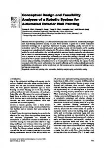
1. Outline of CO2 transportation system CO2 transportation system image is shown in Fig.1. This study examined both demonstration scale (about 240,000ton-CO2/year) and commercial use (about 1,540,000ton-CO2/year), in the following technologies and concept design, except for the CO2 hydrate transportation, which was only demonstration scale study. Each technology and concept design are as shown in following chapters. Liquefied CO2 storage tank (Chapter 2), Ship transportation of liquefied CO2 (Chapter 3) , Offshore gravityy based terminal (Chapter 4) , Floating Offshore terminal (Chapter 5), CO2 hydrate transportation (Chapter 6) , Pipeline transportation (Chapter 7)
Fig.1 Image of CO2 transportation system
2. Liquefied CO2 storage tank (Onshore terminal, Offshore terminal) IIn the shipping and offloading terminals where liquefied CO2 will be transported for shipping, it is required to keep the buffer function inclusive of the stormy weather standby of the CO 2 carrier in order to prevent transportation and storage from stagnation. Here, under the design condition, the specification for Temporary storage tank and its incidental equipment of terminal was determined. Drawing was made and investigation for the lot area required for terminal construction was executed. 2.1. Design condition The state of CO2 handled at the terminal is Liquefied with low temperature and high pressure. Design is executed subject to "High Pressure Gas Safety Act." [1]. The following was thought as a design condition. It is prevented that liquefied CO2, at offloading and shipping, from solidification (piping blockage due to CO 2 hydrate) effected by temperature and pressure change during transportation process. Also, heat insertion treatment, so to speak, a methodology to control n and collect the volume of boil off gas (B.O.G.) was executed. That is, the necessary storage of liquefied CO2 in each terminal for the demonstration scale plant and for the commercial use plant respectively was assumed to be 6,000ton and 24,000ton. The designed pressure value is basically set at 0.8MPaG. The temperature was designed within the range of -46 to -50 degree Celsius in consideration of triple point and to meet the pre-condition as mentioned as above. 2.2. Specification of the CO O2 Onshore tterminal and Offshore O t terminal (includes tanks) For both Onshore and Offshore terminal for liquefied CO2 in the demonstration scale plant, two numbers of 3,000ton spherical tanks (18m inner n diameter) were considered. They were made of alumina
Takakazu Suzuki et al. / Energy Procedia 37 (2013) 2989 – 2996
killed steel (SLA360), a -60 degree Celsius cryogenic steel material (steel plate thickness is 31mm at the max., while minimum site area became approximately 7,000m2 (80m×80m). In addition, the tanks and equipment are stored in the offshore gravity base caisson terminal. In case of the onshore commercial use plant, due to the size, the adoption of 9% nickel steel (SL9N) that had cryogenic performance of -196 degree Celsius was required as a material unnecessary to execute in situ annealing process. As a result, two numbers of 12,000ton spherical tanks (28m inner diameter) were required (plate thickness become 50mm at the max., and the minimum site area is 10,000m2 (150m×66m). In the onshore commercial use plant, the tank adopted 3,000ton cylindrical type in consideration of its well-fitting dimension inside of the caisson. Therefore, the total number of tanks counted eight. In this case, economical alumina killed steel (SLA360) was able to be adopted for the tank material. Additionally, in order to reduce the B.O.G. at each plant, it has been found effective to shorten as much as possible the total length of piping from the liquefaction facility to the tank. Fig. 2 to Fig. 4 shows liquefied CO2 storage tank and the outline chart of the commercial use Onshore terminal.
! ! ! ! Fig. 2 Commercial use CO2 Storage Tank (onshore)! ! ! ! ! ! ! ! Fig. 3 Commercial use CO2 Storage Tank (offshore) 12,000ton (0.8MPaG) × 2 set! ! ! ! ! ! ! ! ! ! ! ! ! ! ! ! ! ! ! 3,000ton (1.0MPaG) × 8 12,000ton CO2 Storage tank 150m
66
2set 10,000m2
21,000ton class CO2 Carrier
Fig. 4 Commercial use Onshore terminal layout ! 10,000m2 (not include pier, loading arm and planting area)
2.3. Obtained results and issues in the future In the demonstration scale tank facility, comparatively economical alumina killed steel (SLA360) can be obtained as a material in accordance with the size of tank. However, operation of the facility requires maintenance and control of appropriate temperature and pressure. The temperature room (surplus) of the steel material is -10 degree Celsius towards operational temperature of liquefied CO2. The 12,000ton tank in the commercial plant requires adoption of 9% nickel steel (Cryogenic performance: - 196 degree Celsius) subject to legal limitation of steel material thickness, annealing condition and others. In this case, from now on, permission to use economic materials and relaxation of
2991
2992
Takakazu Suzuki et al. / Energy Procedia 37 (2013) 2989 – 2996
legal binding such as introduction of 5% nickel steel and pre-stressed concrete material will be expected since there is enough room for liquefied CO2 (-50 degree Celsius).! Since there is no experience in constructing and using a tank in this huge scale for liquefied CO 2 storage both in demonstration and commercial purpose, experiment of the state change during operation and analysis verification are required prior to practical use. As for pre-stressed concrete tank, technology will allow designing at the maximum of 50,000ton size. 3. Ship transportation of liquefied CO2 The conceptual design of liquefied CO2 carrier is carried out for several types of ship on the basis of the experience of LPG and LNG. 3.1 Preliminary investigation (1) Building record of liquefied CO2 carrier. Several liquefied CO2 carriers are constructed, but they are small ship having capacity up to 1,400m3. (2) The applicable ship rules. 1) The liquefied CO2 carrier is designed according to Ships carrying liquefied gases in bulk of Rules for the survey and construction of steel ship published by Classification society. 2) The liquefied CO2 carrier is categorized as Ship type 3G and independent tanks type C. (3) The applicable design temperature and pressure of liquefied CO2. The design temperature for tank is -50 degree Celsius and the design pressure for tank is 1.0MPaG based on the investigation of properties of liquefied CO2. (4) The applicable steel material of CO2 tank. 1) The applicable materials of tank are decided by the design temperature and plate thickness of tank is decided by the design pressure. 2) The applicable materials for tank are steel for low temperature use or nickel steel. 3) The applicable plate thickness is up to 40mm and 50mm in case of special approval. (5) The applicable CO2 tank configuration. The applicable tank structure is pressure vessel and tank configuration is 3 types as shown below.
Cylindrical tank! !
! Bi-lobe tank! ! !
Spherical tank
3.2 Conceptual design ! The conceptual design is carried out for the demonstration scale ship with Carbon dioxide discharge of 240,000ton-CO2/year and for the commercial use ship with 1,540,000ton-CO2/year. The 4 types of ship are designed with the different tank type and capacity. The principal dimensions are shown on table 1. Table1 Qrincipal dimensions of Liquefied CO2 Carrier item
unit
Tank type Length(L) Breadth(B) Depth(D) Draft(d)
m m m m
3,000ton type demonstrational ship cylindrical 95.0 18.4 7.4 4.8
20,000ton type commercial ship bi-lobe 161.0 27.5 17.2 9.4
50,000ton type commercial ship spherical bi-lobe 226.0 240.0 41.0 35.4 19.0 21.5 10.5 11.5
Takakazu Suzuki et al. / Energy Procedia 37 (2013) 2989 – 2996
Fig. 5 20,000ton type commercial ship
4. Offshore gravity-based terminal 4.1 Summary The Offshore terminal installed close to the storage site has the facilities to accommodate berthing and offloading operation for CO2 carrier, to receive temporary storage, and to support pressure risers for the injection of CO2. The conceptual design has demonstrated that the proposed Offshore terminal is able to provide the above services, safety against environmental attacks such as earthquake and storm, and cost merit. The construction method based on the existing technology is also proposed. The gravity-based Offshore terminals are suitable for shallow waters. 4.2 Structural configuration and type of foundation The structural configuration of the terminal has been determined by the survey on the existing technology which covers port structures, offshore LNG terminals and gravity-based platforms for oil and gas development in the North Sea. The terminal of reinforced concrete has the following dimensions to accommodate CO2 containers and to berth CO2 carriers. Commercial use Length 250m Width 42m Height 25m The environmental conditions at the open sea and the geotechnical condition of the sea bottom show that the skirt suction foundation, proven technology in offshore concrete platforms, is applicable to the terminal. The arrival of CO2 carrier at the terminal for commercial use is shown in Fig.6. The study also demonstrates that delayed the arrival of CO2 carriers during heavy weather could be minimized by the wave blocking effect of the gravity- based terminal and a down time is negligible even at the open sea. 4.3 Proposed construction method The terminal of large offshore concrete structure will be constructed at a dry dock, a quay wall and so on. The terminal will be fully loaded with topside facilities there and it will be towed to the installation site.
Fig.6 Schematic view of offshore gravity-based terminal for commercial use
5. Floating Offshore terminal The functions of the floating Offshore terminal are to receive the liquefied CO2 from the liquefied CO2 carrier, which is liquefied at Onshore terminal, to store them at CO2 tanks onboard, to inject them into sea bottom. 5.1 Design condition The water depth at site, the size of the floating structure, and wave/wind condition are shown as follows,
2993
2994
Takakazu Suzuki et al. / Energy Procedia 37 (2013) 2989 – 2996
Water depth at site : 120 m Storage tank capacity for liquefied CO2: ! ! ! ! ! ! !
Demonstration scale terminal : Commercial use terminal: Max. wave height (significant) :
6,000 ton 24,000 ton 10 m
5.2 Conceptual design (1) Demonstrational terminal (shown in Fig.7* As to the facilities onboard, there are two (2) sets of the liquefied CO2 tanks having 3,000 ton capacity each, loading arms, CO2 injection system, power plants and accommodation quarter, etc. The principal dimension of the floating barge is, Loa = 100 m, Bm = 35 m, Dm = 8 m. The multi-anchor chain system was selected because that the design external force by wind and wave has not been so big than expected. (2) Commercial use terminal (shown in Fig.8) As to the facilities onboard, there are eight (8) sets of the liquefied CO2 tanks having 3,000 ton capacity each, loading arms, CO2 injection system, power plants and accommodation quarter, etc. The floating terminal is of octagon mono-column type and the principal dimension is, Loa = 86 m, Boa = 86 m, Dm = 46 m. The mooring system is the multi-anchor chain system. The functions of the floating Offshore terminal are to receive the liquefied CO2 from the liquefied CO2 carrier, which is liquefied at Onshore terminal, to store them at CO2 tanks onboard, to inject them into sea bottom. There are many kinds of structural configuration for the floating Offshore terminal, such as, barge type, ship type, semi-submersible type, TLP type, SPAR type, etc. There are also many kinds of mooring system such as, multi-anchor chain mooring, turret mooring, dolphin mooring, etc. The optimal structural configuration and mooring system shall be determined in accordance with the design conditions at site such as, water depth, wave, wind, soil condition of sea bottom, etc.
Fig.7 The illustration of the demonstrational floating Offshore terminal
Fig.8 The illustration of the commercial floating Offshore terminal
6. CO2 hydrate transportation CO2 transportation as hydrate!pellets will be presumed feasible comparing with liquefied CO2 , since natural gas transportation as hydrate will be feasible under certain condition than LNG. The most important characteristic of hydrates is someans those can exist relatively stable in the atmospheric pressure at well above the equilibrium decomposition temperature as covered with ice membrane. The feature will be utilized for storage and/or transportation in the form of pellets!(solid), which phenomenon and effectiveness was observed in the study of Natural Gas Hydrate (NGH) pellets![2]. The self-preservation phenomenon of CO2 gas hydrate (CGH) pellets and validity of conditions were confirmed by laboratory test ,and the storage condition in tanks and/or in CO2 carriers was decided at -15 degree Celsius under the atmospheric pressure. 6.1 System configuration of CGH transportation
Takakazu Suzuki et al. / Energy Procedia 37 (2013) 2989 – 2996
The scope of CGH transportation system covers after receiving CO2 gas from the Separation & Capture! System at the coal-fired power plant and before delivering to the underground Sequestration System. The components of the CGH transportation system i.e. CGH production facilities and storage tanks!at! Onshore terminal /CGH carriers /the re-gasification units!at Offshore or Onshore terminal were fixed. And the basic conditions of the system such as; the properties of CO2 delivered from upstream, transport volume, transport distance, storage volume and condition after re-gasification were determined. 6.2 Case study of CGH transportation (for demonstration scale) Considering the cruising time from power plant as the source of CO2 to reservoirs as the candidate offshore storage sites, loading/unloading time and wait-on-weather time with the pier restriction, the size and number of CGH transportation fleet were decided as follows; 3,156 ton /day (CGH) Treating volume Deadweight 7,400 ton x 3 ships CGH transport fleet L=125, B=19.4, D=10, d=4.8 (Fig.9) Ship dimension (m) Considering the results of economic evaluation of the demonstration scale system, further study for Commercial use unit (about 6.5 time treating size larger) was not performed.
Fig.9 Image view of the CGH carrier at pier
6.3 Features of CGH transportation The advantages and disadvantages of the CGH transportation system are summarized as follows; (1) Safer transportation by ships under the atmospheric pressure at -15 degree Celsius in spite of increasing transportation volume!than liquid phase transportation. (2) Possibility to improve energy balance by NGH-CGH round trip transportation by the same ship. (3) Possibility to improve energy balance by gas hydrate separation concept (hydrate method). 6.4 Challenging tasks For further study of the CGH transportation system toward full scale commercialization in the future, following challenging tasks should be studied. (1) Applicable laws or regulations to the CGH carriers in view of safety for carrying CGH pellets in bulk. (2) Improvement on the energy required for manufacturing CGH pellets, by means of cold energy utilization, round trip transportation of CGH-NGH by the same ship, and the separation and recovery of CO2 by hydrate method. (3) Optimum shapes and sizes combination of CGH pellets for improving filling rate in tanks and/or holds. (4) Loading and unloading system in the cargo holds and/or storage tanks for effective handling of solid CGH pellets, including measures against adherence of pellets. 7. Pipeline transportation 7.1 Transport conditions In Japan CO2 pipelines must be designed according to High Pressure Gas Safety Act . Based on the same transport volumes of CO2 as the ship transport case (1,540,000 ton- CO2/y), the case study for the
2995
2996
Takakazu Suzuki et al. / Energy Procedia 37 (2013) 2989 – 2996
pipeline was carried out. The length of the pipeline on land is 17km, and the length of the offshore portion is 108km. The maximum depth of the offshore pipeline is 100m. The pressure at the wellhead of the storage formation is specified at 10.5MPaG. Since there is a gasliquid equilibrium curve around 4~6MPaG for CO2 at the normal temperature, it is determined that the operation pressure to be out of this range to make the flow single phase. 7.2 Pipe Material and Corrosion Protection Pipe material was also determined to be usual carbon-manganese steel pipe (API material) in this study. CO2 emitted from the power plant contains approximately 8% of water, but there is no other corrosive elements in the gas. Therefore, the major corrosion protection method for internal surface of the pipe will be removal of water, and water contents in the gas is limited to 100ppm. 7.3 Pipeline System Configuration In Case-1 (Fig.10) CO2 is transported as gas phase throughout the pipeline at a lower pressure (design pressure at 3.5MPaG), and it is pressurized again at the compressor near the storage site. In this case, the external pipe diameter is 610.0mm. In Case-2 (Fig.11) CO2 is transported as liquid phase (dense phase) throughout the pipeline at a higher pressure (design pressure at15MPaG), and it is injected into the formation without compression at the end of the pipeline. In this case, the external pipe diameter is 323.9mm. 7.4 Construction method The in-land pipeline will be buried under roads similar to natural gas transmission pipelines. Offshore pipelines will be laid by a special construction ship called pipe lay-barge. Liquid (super critical p phase))
Gas
Gas
0.10 MPaG, 61 degree Celsius CO2 91.5% H2 O 8.1% H2 0.4%
Capture
Pressure r at seabed well head 10.5 MPaG
Compression
Transport
Compression Compressor and pump
Onshore pipeline Onshore platform
Power plant
Dehydrator and compressor
Offshore Offs hore pip pipelin elinee
Storage
Fig. 10 System configuration of Case-1 (gas phase/low pressure transport) Liquid
Gas 0.10 MPaG, 61 degree Celsius CO2 91.5% H2 O 8.1% H2 0.4%
Capture
Pressure at seabed well head 10.5 MPaG
Compression
Transport
Onshore pipeline Power plant
Dehydrator and compressor Offshore Offs hore pip pipelin eline
Seabed well head
Storage
Fig. 11 System configuration of Case-2 (liquid phase/high pressure transport)
References [1] High Pressure Gas Safety Act (Act No. 204 of June 7, 1951. Revisions of Act No. 50 of June 2, 2006 [2] T. Iwasaki, et al., Research on Selff preservation of Natural Gas Hydrate Pellets, Mitsui Zosen Technical Review, No.187, 2006; p.15-21.