ARTICLE
International Journal of Advanced Robotic Systems
Conceptual Framework for Knowledge-Based Decision Migration in Multi-Component Robots Regular Paper
Laxmisha Rai1 and Jiman Hong2,* 1 College of Information and Electrical Engineering, Shandong University of Science and Technology, Qingdao, China 2 Intelligent Robot Research Center, Soongsil University, Seoul, Korea * Corresponding author E-mail:
[email protected]
Received 6 May 2012; Accepted 8 Feb 2013 DOI: 10.5772/56103 © 2013 Rai and Hong; licensee InTech. This is an open access article distributed under the terms of the Creative Commons Attribution License (http://creativecommons.org/licenses/by/3.0), which permits unrestricted use, distribution, and reproduction in any medium, provided the original work is properly cited.
Abstract This paper presents a conceptual framework for dynamically migrating the decisions of multi‐ component robots within different physical sub‐ components. At the higher layer, a decision‐making distributed migration system embeds the rules written in a knowledge‐based system (KBS). The rules are written and decisions are made at one component, which can be migrated by the underlying distributed system. This eventually results in intelligent migration of the decisions and robot survival, irrespective of a particular physical component failure. Moreover, a robot does not need an exclusive control system for each component. The implementation is a two‐step process. Initially, component‐specific facts are identified and mapped to suit to respective components and to write rules and explore different gestures and behaviour of the robot. The second step is the embedding of these rules within the distributed or agent‐based system and allowing the decisions to float around the system. The Jess (Java Expert System Shell) expert system is used as the knowledge‐based tool and different gestures are generated to realize the proposed method. www.intechopen.com
Keywords Humanoid, Behaviour, Knowledge‐Based System, Migration, Component
1. Introduction The human brain acts as the centralized decision‐making organ of our body; all actions or gestures are indirectly controlled by it. For example, while lifting or throwing a ball, the decisions to lift both the left and right arms are directly stimulated from the brain. It is hard to imagine the messages sent from the left arm to the right arm without the brain’s interruption or by bypassing the brain. In earlier years, researchers developed robots with centralized as well as hierarchical‐based control, which usually follows the patterns of existing biological entities. Even though several processors are specific to each of the components spread within a robot system, usually there is one centralized processor to monitor all other activities or to synchronize multiple activities. In this paper, a component refers to a hardware unit of the robot, which consists of at least one sensor or actuator, or combinations J Adv Robotic Sy, 2013, 10, 237:2013 Laxmisha Rai and Jiman Hong: Int Conceptual Framework for Vol. Knowledge-Based Decision Migration in Multi-Component Robots
1
of both, to achieve either sensing and actuation or both. For example, in a humanoid robot the wrist, elbow, shoulder, neck and torso may represent components. Moreover, simply transferring a control or monitor signal from one processor to another is not meaningful. In such circumstances, new software and knowledge‐based decision‐making models are essential in making the robot operate ‐ even during specific component failure 0 with the ability to migrate the decisions within the robot components. For example, knowledge‐based systems not only decide the most relevant decisions but also overcome non‐deterministic situations. Since components are meant for different roles and activities, in practice there is no need to migrate the knowledge of one component to another. However, if each component is capable of having the knowledge or decision‐making power of the entire system, then the robot can bypass the centralized control in generating any actions. For example, while lifting the ball, the left and right hands can generate one synchronized action without listening to the brain. In this simple scenario, it is not just the control that needs to migrate within the arms, but the decisions for synchronization based upon sensor responses. In the proposed framework, we believe that in biomimetic robots such as snake‐like, legged and humanoid robots, the decisions need not be centralized or hierarchical and can be attached to a particular or single component of a robot, such that any damage to the robot during its real operation will not eventually cause the paralysis of the operation of the entire robot. Earlier, researchers found that uncertainty and the dynamic nature of robots must be taken in into account while a robot performs real‐time operations. For example, a mobile robotʹs behaviour cannot be represented by a simple sequence of robot motions. The robot may change its motion according to environmental situation [1]. The rationale behind choosing a knowledge‐based approach for decision migration is to deal with robotsʹ non‐ deterministic behaviour. This means that multiple executions of a program with the same input may produce different results. This is essential for generating intelligent actions in a non‐deterministic domain and coping with the problem of incomplete information provided by robots in the operating environment. Moreover, nondeterministic factors such as behavioural system constraints, environmental uncertainty and unexpected responses from sensors, as well as interaction with the system environment and managing context‐ sensitive or location‐awareness details also need to be considered [2]. In this context, representing non‐ deterministic behaviour using KBS is highly beneficial. The proposed method is a two‐step process. Initially, various components of a robot are identified and mapped to component‐specific facts. The number of behaviours can be generated by writing rules. The different gestures 2
Int J Adv Robotic Sy, 2013, Vol. 10, 237:2013
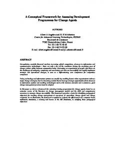
and behaviours are tested using knowledge‐based multi‐ component synchronization and co‐ordination [3]. Secondly, rules are embedded within different client and server programs of a distributed system. Any physical component of the robot can take the role of server or client, since we are aiming at decentralized and non‐ hierarchical knowledge‐based behaviour migration. The migration framework is tested for decision and behaviour migration within different subcomponents. Figure 1 shows the RoMAN robot, which is developed by the NT Research Inc, in Korea [4]. RoMAN has a human‐ like torso on a four‐wheel robot with components such as two wrists, two elbows, two shoulders (DOF=2) and two hands (DOF=1), a neck (pan, tilt, DOF=2) and a mobile base (DOF=2). As shown in Figure 1, treating it as a biomimetic system derived from a human, the head section acts as central control system. In technical terms, one central processor residing in the head section controls the arms and other sections of the robot. Lines 1 and 2 indicate that one control system ‐ such as a brain ‐ controls both components, leading to centralized or hierarchical control. In this case, decisions are sent from the centralized system. However, it is not possible in earlier systems to demonstrate, the decision migration between two robot arms bypassing the centralized system. This will lead to the concept of behaviour migration within the systemʹs components.
Figure 1. Conceptual understanding of decision migration within a humanoid robot
This paper is organized as follows. Section 2 describes the related work; Section 3 describes the software models for decision‐switching within multi‐component robots, which is the motivation for this work. Section 4 describes a conceptual overview of the proposed knowledge‐based behaviour migration. The experimental evaluation is given in Section 5 and, finally, concluding remarks are presented in Section 6. www.intechopen.com
2. Related Work The field of biomimetics has fostered innovative design collections, sought new paradigms and methods, and designed new streams of intelligent machines, robots, systems and algorithms. Biologically‐inspired approaches can create a new reality with great potential. They have been utilized to advance the development of innovative robotics through the integration of bio‐inspired ideas and solutions into engineered systems [5‐6]. Similarly, researchers also provided experiments conducted on robots for intelligent decision‐making, path planning and navigation [7]. In recent years, several researchers have developed distributed architectures as against centralized and hierarchical architectures for controlling and operating robots in real environments. Researchers in [8] discussed the CORBA‐based (Common Object Request Broker Architecture) distributed software architecture for the control of service robots. They focused on the robot’s ability to learn task knowledge. This paper also discusses the disadvantages of those hierarchical architectures which are based on a top‐down approach. The advantage of a hierarchical system is that: planning is easy, as there is a superior view of the system. A drawback of these systems is their insufficient reactivity to dynamical environments. A multi‐agent‐based distributed control system for an intelligent robot that is an integration of many functional modules is presented in [9]. According to the full requirements of this system, many agents and a distributed blackboard system are designed so that the system realizes very flexible robot control from a low level ‐ such as servo control ‐ to a high level control, such as motion planning. In particular, it analyses the functions of agents and presents the results of preliminary experiments with a real robot system. In [10], a distributed real‐time software framework for robotic applications is proposed whereby experiments were conducted in order to compare the performances of the proposed system with the performances of a centralized system. The results show that the distributed system uses less system resources, gives better real‐time performances and satisfies the requirements of a dual‐arm mobile robot. In addition, there are cases where agent‐based systems are used for robot control and multi‐robot cooperation. In an agent‐based architecture, agents can communicate, coordinate and negotiate to meet their goals in a framework suitable for task execution. The architecture proposed in [11] supports both centralized and distributed (agent‐to‐agent models) arrangements. An agent‐based robot control (ARC) architecture with features of a flexible real‐time control system, which is suitable for multi‐robot cooperative tasks, is given. The aim is to integrate multiple heterogeneous autonomous robots into a coordinated system that is modular, scalable www.intechopen.com
and efficient. In [12], researchers presented an agent‐ based distributed architecture for programming and controlling teams of mobile robots. The main objective of this work was to perform cooperative tasks with a team of heterogeneous robots. A multi‐level and distributed architecture based on the reactive/deliberative paradigm is presented in [13]. Its main components are mobile software agents that interact through a distributed blackboard communications framework. In our earlier research [3], we demonstrated experiments conducted on a Humanoid robot for generating intelligent gestures using a knowledge‐based system (KBS). The Jess (Java Expert System Shell) [14] expert system was used as the knowledge‐based tool and different gestures were generated autonomously using different rules. With this approach, any user could generate any purposeful behaviour using simple facts and rules to demonstrate different robot action sequences. In [15], we proposed a new modular software and hardware architecture for multi‐shaped robots using real‐time dynamic behaviour identification and selection. The intelligent dynamic selection and synchronization of selected behaviours enabled the mobile robots to perform many tasks in complex situations. Robots ‐ such as Humanoid ones ‐ are complex systems which are characterized by high functional and spatial integration. The segmentation of the total system of the humanoid robot is oriented on the interactions present in a system [16]. In automation systems, middleware can be considered as an abstracting and uniting layer between an entityʹs hardware, its low‐level control and the high‐ level control of the entire system. It is an advantage of middleware‐based systems that various control architectures ‐ e.g., group, distributed, supervisory control, client‐server interaction etc. ‐ can be implemented within the same generic middleware‐based platform [17]. However, in the previous studies, even though researchers focused on distributed control as against centralized and hierarchical control in robots, they failed to explore the possibilities of decision migration within the components of a robot along with a knowledge‐based system. However, data migration ‐ rather that decision migration ‐ has been explored by many researchers earlier on. Regarding the research relating to migration schemes, a concept of data migration in a distributed, object‐oriented knowledge base is discussed in [18]. Here, the researchers proposed the distribution and migration of data to several databases within a distributed knowledge base. The main part of the migration method is a distribution function, which generates an optimal distribution of data on the databases according to the defined aims. Similarly, there are other approaches, such as DJess [19], which is a novel distributed production system that provides an Laxmisha Rai and Jiman Hong: Conceptual Framework for Knowledge-Based Decision Migration in Multi-Component Robots
3
infrastructure for factual and procedural knowledge sharing. DJess is a Java package that provides programmers with lightweight middleware, by which inference systems implemented in Jess and running on different nodes of a network can communicate. However, none of the earlier works on migration are applied to robots. 3. Software‐Models for Decision Switching within Multi‐Component Robots In this section, we explore cases where the use of software models has enhanced decision migration in real robot applications. Software models provide low flexibility and uncertainty in handling while making complex decisions as compared to knowledge‐based systems. However, software models also provide for decision switching, as in the case of threads and recursive procedures. The successful implementation of such cases ‐ which are implemented by the authors and are presented here ‐ where a simple programming model is constructed using threads and semaphores can effectively derive behaviours in snake‐like and legged robots [20]. With this approach, the robots such as snake‐like and four‐legged robots are divided into smaller modules called ʹunitsʹ (or ʹcomponentsʹ) and ʹsectionsʹ. The combination of many components makes a section.
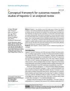
understanding the relationship between two adjacent sections. In the same way, the threads and semaphores were used to synchronize this relationship between two adjacent sections to generate a walking behaviour in four‐ legged robots. However, in all these cases, N numbers of threads are required in a robot with N sections. Videos of these robots can be viewed at: http://rtlab.knu.ac.kr/robots.htm. Figure 2 shows the schematic which describes the snake‐like robots sections, and units, and Figure 3 shows its physical prototype. Pseudocode of such an application is presented in Figure 4.
Units
k p
k+1 p+1
p
p+1
Sections
Figure 2. A schematic which explains a snake robot’s sections and units
Figure 3. Physical prototype of a snake‐like robot
For example, a snake‐like robot may have N sections (1≤ k≤ N) and each section may have M units (1≤ p≤ M). The total number of units = N×M. Similarly, an N‐legged robot may have a maximum of N sections ((1≤ k≤ N) and each section may have M units (1≤ p≤ M). The total number of units required for any movement is N×M. To emulate the snake‐like robot, four‐legged behaviour threads and semaphores are used. These kinds of applications need a maximum N (1≤ k≤ N) number of threads. The wave movement of the snake is realized by 4
Int J Adv Robotic Sy, 2013, Vol. 10, 237:2013
Figure 4. The pseudocode for synchronizing between two sections using the threads (a) and (b) of a multi‐component robot for generating purposeful locomotion in snake‐like or legged robots
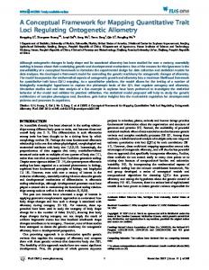
As each thread is operating independently on specific sections of the robots, in the case of physical damage or failure of any section, they continue to work without effecting the robotʹs behaviour or total robot failure. This shows that decisions about robot behaviour are migrated within multiple sections with synchronization using semaphores. However, synchronized threads will provide less flexibility while dealing with complex robots, such as humanoid ones with multiple subcomponents. In such cases, knowledge‐based systems are essential. 4. Conceptual Framework for Knowledge‐based Behaviour Migration The proposed implementation environment is a layered architecture with four layers, as shown in Figure. 5. This includes middleware, knowledge processing, behaviour migration and a physical device layer. The middleware layer forms the top layer of the architecture and is responsible for providing distributed support for www.intechopen.com
behaviour migration and achieving the request and response within multiple components during the operation of components. It works to embed multiple rules written in KBS so that the migration of behaviour is possible within different components. As complex biomimetic robots ‐ such as humanoid ones ‐ need cooperation from multiple subcomponents, there are numerous requests related communication that need to be managed effectively. These requests and responses need to be managed both within components as well as with other components. The middleware layer will also manage the complexities involved in the flow of control where hierarchical, non‐hierarchical, centralized and decentralized flows are essential in managing exceptional events. Tools such as CORBA [21‐22] and client‐server programming are enabled to realize the behaviour of distributed scenarios and in managing exceptional events. The knowledge processing layer is responsible for knowledge acquisition, reasoning and decision‐making. This includes multiple rules and facts, such that the number of rules can be written. The knowledge processing layer is constituted with the knowledge‐based or expert systems as its components. In addition to the requirement for fast execution, the expert systems ‐ such as Jess [14] and CLIPS (C Language Integrated Production System) [23] ‐ also possess the ability to perform context focusing, interrupt handling, temporal reasoning, uncertainty handling and truth maintenance [24]. This layer also allows the user to test the physical or behavioural constraints of any component of the robot. Moreover, autonomous decision‐making rules can be written to perform specific actions based on sensor responses or environmental conditions. This layer controls the whole process of applying the rules to the working memory in order to obtain the output of the system. It includes the working memory, rule‐base, pattern matcher and inference engine.
robots. The decisions at a particular component or the decisions of the entire system can also be stored in the different components. The migration of behaviour is required when a particular component fails to perform an expected action. For example, if the left arm of a humanoid robot fails to get a particular response, then it can convey the same action to the right arm to perform. In this case, the parameters to rules need to be mapped in such a way whereby the right arm performs the action with the expected component‐specific parameters, as shown in Table 1. Similarly, if the left arm of the robot is ready to pick up an object ‐ where two arms are necessary ‐ it can migrate the decision to the right arm of the robot to co‐operate. Similarly, if the left arm fails to pick up an object ‐ where only one arm is necessary ‐ it could also migrate such a decision to the right arm without the knowledge of any other components. Decisions are carried out at specific components of the robots in order to perform a specific task. The facts and rules are written in a such way that decisions are attached to the specific hardware components of the robot. The behaviour migration layer also provides for the ability of synchronized coordination and failure management. The physical device layer includes the actual physical robot, along with its subcomponents, which in turn include a number of sensors, actuators, communication modules and processors. The modules related to communications are responsible for actions in the external environment. This might comprise a sensor/actuator network, in order to efficiently manage several sensors or actuators mounted on the subsystem components. For example, the CAN protocol [25] can be used for communication between sensors and actuators within the subsystem for guaranteeing hard real‐time communication. Similarly, many robots currently include dedicated wireless sensor network protocols, such as ZigBee [26‐27], which can greatly facilitate communication within the external environment. The decision at the higher layer triggers the behaviour or decision migration in the lower layer for a purposeful interaction with the external world. Based on the sensor values read from the different components of robots, different rules are fired to accomplish a particular task. The distributed ‐ or agent‐based ‐ system at the top layer supports the migration of these decisions and behaviours to other components as and when necessary. 5. Experimental Evaluation
Figure 5. System architecture of the proposed framework
The behaviour migration layer is the layer for migrating the decisions within multiple subcomponents of the www.intechopen.com
The implementation of the proposed architecture consists of two steps. Initially, the robot’s physical components which contribute to the overall gesture or behaviour generation are recognized. After identifying the components ‐ such as the neck, arms and hands ‐ the different actions possible in these components are identified. These action sequences are mapped to different Laxmisha Rai and Jiman Hong: Conceptual Framework for Knowledge-Based Decision Migration in Multi-Component Robots
5
facts in a knowledge‐based system, such as Jess. Using these facts, the different rules are written to generate purposeful gestures [3]. In the second step is the integration to the distributed system, where the client or server programs are written in such a way that, they can embed multiple rules written out of facts created in the first step. Moreover, we can also bind the user‐defined services to generate purposeful operations for the robot. To carry out the experiment, different software tools are identified. For example, for the implementation of the middleware and CORBA, and for implementing the knowledge‐base, we have identified Jess [14] and CLIPS [23]. 5.1 Experimental Setup
5.2 Adding Commands to Jess The Java interface jess.Userfunction represents a single function in the Jess language. We can add new functions to the Jess language simply by writing a class that implements the jess.Userfunction interface, creating a single instance of this class and installing it into a jess.Rete object using Rete.addUserfunction(). The Userfunction classes ‐ written by the users ‐ can maintain a state; therefore, a Userfunction can cache results across invocations, maintain complex data structures or keep references to external Java objects for call‐backs. fact name
Experiments were carried out with the RoMAN robot developed by NT Research Inc. in Korea [4]. Jess (Jess 7.1p2) is installed on a Windows XP‐based PC. To add the new facts to Jess, modules are written in Java, JDK 1.7.0 [28], and class files are included in the Jess directory to make the robot component modules a part of the Jess expert system. These modules actually represent the facts in Jess. For example, the class file Hand_Close in the Java module is included in the Jess directory and then it can be called from the Jess rules as fact along with its parameter, AN. Jess is a rule engine ‐ a special kind of software that efficiently applies rules to data. A rule‐based program can have hundreds or even thousands of rules, and Jess will continually apply them to data stored in its working memory [29]. The rules might represent the knowledge of a human expert in some domain, a set of business rules, a technical specification, or the rules of a game. A Jess rule is something like an if... then statement in a procedural language, but it is not used in a procedural way. While if... then statements are executed at a specific time and in a specific order, according to how the programmer writes them, Jess rules are executed whenever their if parts are satisfied, given only that the rule engine is running.
Parameters
Arm_Move
AN,X, Y, Z
Arm_Joint
AN, θ1, θ2, θ3, θ4, θ5
Arm_Homing
AN,JI
Arm_Positioning
AN
Hand_Move
AN,SP
Hand_Open
AN
Hand_Close
AN
Neck_Home
‐
Neck_Move
N, SP
Neck_Pan Neck_Tilt
N N
Description Move the position of RIGHT/LEFT arm with X, Y, and Z rectangular coordinates (AN=1 for RIGHT, 2 for LEFT). Move the 5 joints of the RIGHT/LEFT arm with mentioned angles (degrees) (AN=1 for RIGHT, 2 for LEFT). Arm homing based on joint index (JI) of the RIGHT/LEFT arm (AN=1 for RIGHT, 2 for LEFT) (JI range, 1~5). RIGHT/LEFT arm home positioning (AN=1 for RIGHT, 2 for LEFT). RIGHT/LEFT hand and wrist control (AN=1 for RIGHT, 2 for LEFT). RIGHT/LEFT hand open (AN=1 for RIGHT, 2 for LEFT). RIGHT/LEFT hand closing (AN=1 for RIGHT, 2 for LEFT). Neck home positioning. Pan‐Tilt move control (N, 1‐Tilt move, 2‐ Pan move, and SP, step pulse, 0~1023). Pan move control. Tilt move control.
Table 1. List of different component‐specific facts
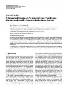
Figure 6. Description of the Hand_Close module 6
Int J Adv Robotic Sy, 2013, Vol. 10, 237:2013
A single Userfunction can be a gateway into a complex Java subsystem. Each Jess rule engine holds a collection of knowledge units called facts. The working memory includes the collection of all facts. Working memory is important because rules can only react to additions, deletions and changes to working memory. To implement, user‐defined commands, the Userfunction interface is used along with two methods: getName() and call(). Figure 6 shows the pseudocode of a module to implement the Hand_Close command. This command www.intechopen.com
serves to close the robot hand (with all the fingers are clamped inside), based on the parameter (Arm Number, AN). If AN=1, the right hand fingers are closed or, if it is equal to 2, then the left hand fingers are closed. As the robot includes a number of components such as a neck, hands and arms, a number of modules are written using the Java language and added to Jess. Later, these modules act as facts and combinations of facts which can be used to write any rules. Table 1 lists the details of the different component‐specific facts added to Jess that are related to the humanoid robot and their parameters.
However, intelligent gesture generation includes multiple rules, which in turn include several facts. Figure 10 shows an example rule which guides the robot to perform several actions. The robot first bends the neck pan and then move both hands and, finally, lift up the neck pan. This kind of sequence is especially useful in greeting the guests in different cultures. As shown, the rule includes the Jess command load‐function to load the user functions. The rule shown in Figure 10 is executed when we assert the following: (assert (beh greeting)).
Figure 10. Rule for generating a greeting gesture
5.3 System Decisions at Particular Subcomponents Figure 11 shows the overall implementation of the proposed system. As shown, the different subcomponents ‐ such as the arm and head sections ‐ are mapped to different sets of facts and these components have the ability to hold knowledge or decisions derived from the rules of all facts. In Figure 11, the knowledge‐based system forms the outer layer (even though KBS is embedded within distributed or agent‐based programs, such as CORBA) to describe the flow of knowledge around the distributed platform. The distributed system provides a framework for migration. It is also responsible for dividing the system components into different nodes of servers and clients. In the present scenario, we have tested it using different scenarios of migration ‐ i.e., from neck to legs and from the right arm to the left arm. The implementation architecture does not focus on a centralized architecture, whereby a PC stores the knowledge‐base as a centralized processor. The Rete algorithm is the backbone of the knowledge‐based system; the executions are not executed sequential [30]. As such, the architecture naturally overcame the majority of loopholes in the current architecture. In addition, the architecture is more meaningful when the system includes more than one processor. For example, a processor loaded at the left arm section can hold all the information of the neck section too, and can check the status of the neck section passively. It can also act as a fault tolerant processor in the case of failures.
Figure 7. The execution of facts (a) Initial gesture, (b) after execution of Arm_Joint and (c) Arm_Move
Figure 8. (a) Hand_Open and (b) Hand_Close facts operations applied to both hands simultaneously
Figure 9. Results of the execution of a standalone fact Hand_Close to clamp the robot right hand www.intechopen.com
Figure 11. Agent‐based/distributed migration implementation showing different subcomponents of a humanoid robot and related facts Laxmisha Rai and Jiman Hong: Conceptual Framework for Knowledge-Based Decision Migration in Multi-Component Robots
7
5.4 Behaviours with Multiple Priorities In this section, we explore complex rules for decision‐ making based on priority. In Jess, each rule has a property called salience that is a kind of rule priority. Activated rules of the highest salience will fire first, followed by rules of lower salience. In order to force certain rules to always fire first or last, rules can include a salience declaration. Declaring a low salience value for a rule makes it fire after all other rules with higher salience. A high value makes a rule fire before all the rules of lower salience. The default salience value is zero. The assigning of a priority level to different actions and behaviours is important while performing complex operations. In some situations, various modules may be assigned higher priority than other modules. For example, usually the right arm has more priority than the left arm. Moreover, when multiple sensory events occur, there is a need to determine the synchronization of the actions. There are also cases where the priority levels assigned to different sensory processing modules are predetermined, as in [24]. If multiple behaviours are available for the chosen task, then the important step is to determine which behaviour to use. This can be done by assigning different priority levels ‐ as shown in Figure 12 ‐ based upon the importance of the behaviour. The other ways of deciding which behaviours are most important involve determining the probability of the success of a given behaviour and considering its cost.
Figure 13. Activation of rules when the rules shown in Figure 12 are fired
Figure 12 gives an example, where three rules (rule‐1, rule‐2 and rule‐3) are defined with (low, high and default) different salience levels. In this application, the right arm is forced to have lower salience than the left arm. Thus, the left arm action defined in rule‐2 executes prior to the other two rules. Figure 13 shows the execution sequence of these three rules and also shows the contents in the agenda. When there are multiple activations on the agenda, Jess automatically selects which activation is appropriate to fire. For example, and as shown in Figure 12, it is rule‐2 which has highest activation and which it is appropriate to fire first. These kinds of rules are necessary when dealing with dangerous or critical situations. Based on the sensory information, the robot can choose the most important rule to fire in complex situations. 5.5 Distributed Decision Migration
Figure 12. Rules with a salience declaration
8
Int J Adv Robotic Sy, 2013, Vol. 10, 237:2013
CORBA is a widely recognized by the control community as object‐oriented, open‐standard‐based middleware for distributed systemsʹ integration. CORBA supports the interoperability, portability and reusability of systems’ components. Moreover, its real‐time and fault‐tolerant specifications have recently been developed [21‐22]. The CORBA component’s interface is described in a neutral Interface Definition Language (IDL). CORBA IDL is a declarative non‐programming language; it does not provide any implementation details [18, 31‐32]. Clients do not need to know where on the network the objects reside, how they communicate, how they are implemented, how they are stored or how they execute. Before a client can issue a request to an object, it must hold an object reference for that object [33]. CORBA programs are written and distributed server and client programs are linked to Jess by embedding the rules shown in Figure 14. However, as the execution of CORBA involves several steps, the complete integrated system with CORBA is not yet realized. As such, programs using client‐server architecture are implemented and tested to prove the decision migration for two different decisions www.intechopen.com
using simulated sensor values. In this case, we have installed Jess in two different machines, which are mapped as two arms of humanoid robots and which embed the rules within the client and server programs to migrate the decision results. The skeleton of both the client and server programs for decision migration with the Jess rules are shown in Figure 15(a) and Figure 15(b) respectively.
Figure 14 Embedding Jess rules in a CORBA client program
As shown in Figure.15(a), the right arm of the robot acts as a client and performs arm movement based upon a simulated touch sensor value (tsv). The actions are performed when the tsv value is less than or equal to 200. As soon as this action is performed, the information is sent to the server program, which is shown in Figure 15(b), and the server code executes the rule to perform the left arm action, which is synchronized with the right arm. In this way, the decisions are migrated between the client and server programs.
import jess.*; import java.net.*; import java.io.*; import java.util.*; public class ClientCode { ……………… public ClientCode(){ try{ Socket socket = new Socket("192.168.143.129", 8080); //Target IP address of left arm processor ……………… out.write (Message, 0, Message.length ()); }catch(Exception e){} } public static void main(String[] argv) { ClientCode c=new ClientCode(); } public String getCode(){ ……………… try{ Rete engine = new Rete(); engine.eval(“ (defrule arm_right_rule (get_touch_sensor_value ?tsv) => (if (