Dec 8, 2005 - Biarritz, France, November 8th â November 10th, 2005. 69. -1-. Copyright ... specifying a VR application at a conceptual level, free from ... Studio Max [2]). Authoring .... The STEP (Scripting Technology for Embodied Persona) language is ...... behavior, we build a front-end in Microsoft Visio to allow creating ...
Proceedings of Virtual Concept 2005 Biarritz, France, November 8th – November 10th, 2005
Conceptual Modeling of Object Behavior in a Virtual Environment Bram Pellens, Olga De Troyer, Wesley Bille, Frederic Kleinermann
WISE Research Group Vrije Universiteit Brussel Pleinlaan 2, B-1050 Brussels, Belgium Phone: +32 2 629 37 13 / Fax: +32 2 629 35 25 E-mail : {Bram.Pellens, Olga.DeTroyer, Wesley.Bille, Frederic.Kleinermann}@vub.ac.be
Abstract: Today, the design of a Virtual Reality (VR) application is still a specialized and time consuming task. Many techniques and software tools have been created to facilitate the development process. However, they all require considerable knowledge of VR technology. Furthermore, modeling the behaviors of the objects in a Virtual Environment requires programming skills. For this reason, we have developed an approach called “VR-WISE” that allows specifying a VR application at a conceptual level, free from any implementation details, and from the viewpoint of a domain expert, allowing non-VR experts to participate in the design of a Virtual Environment. This approach uses ontologies, incorporating domain knowledge, and high-level modeling concepts for describing the Virtual Environment. In this paper, we explain how object-behavior in a Virtual Environment can be described at a conceptual level. We show how simple behaviors can be combined for composing more complex behaviors. We illustrate the different modeling concepts by means of examples. Key words: Conceptual Modeling, Virtual Reality, Highlevel specifications, Behavior
1- Introduction
Although the creation of Virtual Reality (VR) applications is supported by a number of software tools, the development of a VR application is still a specialized and tedious task. The tools available today for developing VR applications can be classified in two categories. The first category consists of the so-called toolkits (like Performer [1]). Toolkits are programming libraries that provide a set of functions with which a skilled programmer can create VR applications. The second category is the one of the authoring tools (like 3D Studio Max [2]). Authoring tools are complete programs with graphical interfaces for creating Virtual Environments without having to resort to detailed programming. Although these tools assist the developer in creating a VR application, they require
69
-1-
considerable background knowledge about VR technology. Current practice for developing a VR application is that first an authoring tool is used to create the static part of (parts of) the Virtual Environment which is afterwards imported in a toolkit where the code for behavior is added, either by means of a special script language or by means of a traditional programming language. When developing a VR application, a first snag encountered is the necessity to translate the domain objects needed in the Virtual Environment (e.g. a house), into a combination of VR primitives (such as cylinders, spheres, textures, …) and free deformations. None of the available VR development tools allow the developer to specify the Virtual Environment in terms of domain concepts. We illustrate this with VRML, the Virtual Reality Modeling Language [3]. Although VRML allows the developer to create 3D content without having to deal with the low-level details of the platform or rendering process, the developer still has to specify the concepts using low-level primitives like a sphere and a cube. Another observation is that the design phase in the development process of a VR application (from the perspective of a classical software engineering life cycle) is usually a very informal activity. Few formal techniques in the context of VR exist to support this phase effectively. A systematic approach that uses the output of the design phase as input for the implementation phase does not exist. Especially for the behavioral part of a VR application no true design is done. Adding an explicit design phase to the development process of a VR application could also meet the first snag mentioned. If the design phase is at a conceptual level, the design of a Virtual Environment can be expressed in terms of domain concepts. This could make the design also accessible for non-VR experts such as domain experts. In addition, tools can be developed that may assist in the translating of the domain objects into VR primitives. With this in mind we developed a new approach called VR-WISE
Copyright Virtual Concept
Virtual Concept 2005
Conceptual Modeling of Object Behavior in a VE
[4] that supports an explicit conceptual design phase for VR applications. It provides a set of high-level modeling concepts to allow modeling a VR application using knowledge from the application domain. To achieve the use of domain knowledge, the approach uses (domain) ontologies [5][6]. When we developed the set of high-level modeling concepts to support this design process, we carefully watched over their intuitiveness for non-VR experts. However, as we also wanted to investigate how to derive an implementation from such a conceptual design, it was also important to take their expressive power into account. The expressiveness of the modeling concepts needs to be high enough to be able to serve as input for the implementation process (automatic code generation). The modeling concepts also need to be unambiguous. Unambiguousness is needed from the perspective of the designer but also from the perspective of code generation. Also a graphical notation for the modeling concepts is provided. This will enhance the communication between the designers, programmers and other stakeholders. It is also more efficient in use. In this paper we will mainly focus on the modeling concepts developed for modeling behavior in a VR application. The concepts proposed are so called action-oriented by which we mean that they focus on the actions that an object needs to perform rather than on the state of the object. Specifying the behavior in such a way is more natural for non-professionals. This allows involving them more into the specification process. Furthermore, the behavior can be specified independent from the objects on the one hand and from the interaction used to invoke the behavior on the other hand, thereby improving the reusability.
interrelated aspects: form, function and behavior. These three aspects need to be modeled simultaneously. A tool called ADASAL/PROTO has been developed to support the modeling process. It allows specifying the VR application by means of a set of graphical diagrams. These approaches define methodologies for designing a VR application at a conceptual level. However, they do not allow expressing the modeling of the VR application in terms of the application domain. The ontology-based approach of VRWISE allows incorporating domain knowledge that can be used in the development process and hence the VR applications can be expressed in terms of the application domain. The design of Virtual Environment behavior has been addressed in [9]. The Flownet formalism is being used as a graphical notation for specifying the behavior. The discrete part is described using Petri-nets while a notation based on system dynamics describes the continuous part. The Marigold toolset can be used to specify the behavior diagrams [10]. However, even for simple behaviors, the specification becomes large and difficult to read and is therefore not suitable for non-VR experts. The VR-WISE approach allows specifying the behavior in terms of simple actions combined by means of relationships which closely relates to the mental representation of a non-VR expert.
Another methodology, called Rube [11], facilitates dynamic multi-model construction and reuse within a 3D immersive environment. It allows the designer to build models in 3D, using personalized metaphors for well-known modeling formalisms like state machines, Petri nets, etc. Although the The paper is structured as follows. In the next section we will metaphors make it easier for unskilled people to model discuss related work concerning methodologies for developing simple behavior, still, more sophisticated behavior results in VR and high-level behavior modeling. Section 3 will introduce a complex 3D behavior model. the VR-WISE approach. In section 4 we will give an overview of the modeling concepts for describing object behavior within Our work is also related to the PiP model [12]. PiP is a the VR-WISE approach together with their graphical programming by demonstration system that allows a designer representation. An elaborated example will demonstrate the to create object behavior directly in the Virtual Environment concepts. In section 5 we will discuss tool support and its use using 3D interaction techniques. But again, complex into a larger research project, the VR-DeMo project. The paper behaviors are difficult to model within this system. ends with a conclusion and future work. The work presented here is also related to the modeling of Smart Objects described in [13]. Object behavior is defined using a script language consisting of a number of instructions 2- Related work that can be combined with each other. The instructions allow As already explained in the introduction, VR-WISE uses hightriggering movements on the objects. Complex behavior is level conceptual design specifications in order to facilitate the dealt with by means of templates organizing the most development of a complete Virtual Environment. commonly used behaviors. However, a textual language like this is not easily accessible by untrained users. The lack of high-level design methodologies for Virtual Reality development has been addressed in [7] with the The STEP (Scripting Technology for Embodied Persona) presentation of VRID (Virtual Reality Interface Design). Four language is a scripting language that is mainly designed for key components are identified for designing Virtual Reality the specification of communicative acts on embodied agents interfaces: graphics, behaviors, interactions and in the Virtual Environment [14]. A number of primitive communications. The VRID methodology divides the design actions are defined together with a set of operators to process into a high-level design phase and a low-level design combine these actions into more complex movements. The phase. most important operators par and seq, for creating respectively parallel and sequential behaviors, are not In [8], a software engineering approach is presented to design intuitive enough and are therefore not appropriate to be used Virtual Environments. The specification is divided into three by non-skilled people. VR-WISE allows behavior
69
-2-
Copyright Virtual Concept
Virtual Concept 2005
Conceptual Modeling of Object Behavior in a VE
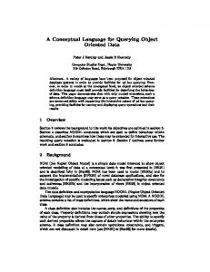
composition by means of a set of time concepts. VR-WISE need to be created but can be an existing ontology originally also introduces a way to trigger the behaviors either at a used for other purposes. specific point in time or as a reaction to some user interaction. The second ontology, the World Specification, will contain In summary, some work has already been done on conceptual the actual conceptual description of the Virtual Environment modeling of Virtual Environments, as well as on high-level to be built. This ontology is created by instantiating the specification of behavior. Most approaches use graphical concepts given in the Domain Ontology. These instances notations or textual descriptions. The main difference with represent the objects that will populate the Virtual these approaches is the use of more intuitive modeling Environment. For the architect example, there will be a concepts and the use of ontologies, which gives us many number of Wall-instances, multiple Window-instances and Door-instances. In addition, instance specific information, advantages as will be shown in the next section. (e.g. size, color, location and orientation) and information specific for the world itself (e.g. gravity, lights…) is given in the World Specification. 3- VR-WISE approach To provide the context of our research, we will first give a To define the concepts, their properties and relationships in general overview of our approach, called VR-WISE, to build both the Domain Ontology and the World Specification, a VR applications. More details about the approach can be found number of high-level modeling concepts are provided. These in [15]. modeling concepts are independent of any application domain and are defined in a so-called upper ontology [16]. The goals of the research are to facilitate and shorten the We have called this ontology, the Virtual Reality Conceptual development process of Virtual Environments by means of Modeling Ontology because it acts as a repository of our VR conceptual specifications (also called a conceptual model). A modeling concepts. conceptual specification is a high-level representation of the objects in the Virtual Environment, how they are related to Specification step (1) each other, how they will behave and interact with each other Virtual Reality and with the user. Such a conceptual specification must be free Conceptual Modeling Ontology from any implementation details and not influenced by the « uses » « uses » current technical limitations of the VR technology. The use of a conceptual model will improve the reusability, extensibility « instantiation of » Domain World and modularity of the VR application. Ontology Specification As underlying representation formalism for the conceptual specifications, VR-WISE uses ontologies. Ontologies are used for two different purposes. (1) Ontologies are used explicitly during the design process for representing knowledge about the domain under consideration. (2) Ontologies are also used (internally) as general information representation formalism. This means that the modeling concepts developed, are described by means of an ontology and that all information collected during the design phase are maintained in ontologies. The design process in the VR-WISE approach is divided into three (mainly) sequential steps, namely the specification step, the mapping step and the generation step (see figure 1). We will now briefly discuss these three steps.
Mapping step (2) Domain Ontology
Conceptual Mappings
World Specification
Generation step (3) Domain Ontology
The specification step allows the designer to specify the Virtual Environment at a high level using domain knowledge and without taking any implementation details into account. During this step, two ontologies are used. The first ontology, the Domain Ontology, describes the concepts (comparable to object types in OO-design methods) available in a domain under consideration for the application. Such an ontology describes the domain concepts by means of their properties as well as their relationships. For example, in the architectural domain, this ontology would contain concepts like Wall, Door, Window, Beam, and relationships such as “a Door is always located in a Wall”, “a Room consists of a number of Walls”. Note that this ontology does not necessarily
69
-3-
Virtual Reality Lang. Ontology
World Specification
Virtual Reality Application « using » Conceptual Mappings
Figure 1 : VR-WISE approach
The mapping step involves specifying the mappings from the conceptual level into the implementation level. This step also uses two ontologies. The Domain Mapping defines the mappings from the concepts in the Domain Ontology to VR implementation primitives. The purpose of this mapping is to specify how a
Copyright Virtual Concept
Virtual Concept 2005
Conceptual Modeling of Object Behavior in a VE
domain concept should be represented in the Virtual Environment. For example, in the architectural domain, a Beam could be mapped onto a box1. The low-level VR concepts that can be used in the mappings are described in an ontology called the Virtual Reality Language Ontology. The concepts in this ontology can be used as target concepts in the mappings.
object, actors are used in the definition of a behavior instead of the actual object(s). An actor is a kind of abstract object. An actor is graphically represented by a circle with the name of the actor written inside (see figure 2a). Figure 2b shows an actor called ‘Door’. For an actor, we only indicate the minimal properties needed to have the specified behavior (not shown graphically here). This implies that each object that has those minimal properties can replace the actor and Although instances may be of the same type (concept), they thus have the defined behavior (see section 4.2). may in some cases require different representations. Therefore, the World Mapping allows defining the mappings from the instances in the World Specification onto concepts in the VR actor Door Language Ontology and thus allows the designer to override the default mappings, specified for the concepts in the Domain (a) (b) Mapping. For example, some Beams will have a round shape and therefore should be mapped onto a cylinder instead of onto a box (which was specified as the default mapping). Figure 2 : Actor The generation step will generate the actual source code for the Virtual Environment specified in the specification step using the mappings defined in the mapping step, i.e. the conceptual specifications given by means of the Domain Ontology and the World Specification are converted into a working application by means of the conceptual mappings given by the Domain Mapping and the World Mapping.
Generalization/specialization can be used as an abstraction mechanism. A generalization/specialization link can be defined between two actors (as shown in figure 3a). It represents a relationship between a more general actor (parent) and a more specific actor (child). The child actor inherits all the behavior defined from the parent actor and optionally adds additional behavior or overrides inherited behavior.
4- Modeling Behavior in VR-WISE
In this section we will introduce the VR-WISE modeling concepts developed for specifying behavior, together with their graphical notation. The behavior specification process is divided into two steps, the behavior definition and the behavior invocation. Both steps will be explained in more detail and examples will be presented. 4.1 - Behavior Definition
The first step of the behavior modeling process consists of building Behavior Definition Diagrams. A Behavior Definition Diagram allows the designer to define the different behaviors for an object. Note that in our approach, the behaviors of an object are defined separated from the structure of the object and independent of how the behavior will be triggered. This improves reusability and enhances flexibility since the same behavior definition can be reused for different objects (if different types of objects have the same behavior) and the same behavior can be triggered in different ways (e.g. by some user interaction or by a collision with another object). We will first explain the different modeling concepts that can be used in a Behavior Definition Diagram.
parent
Door
child
Sliding Door
(a)
(b)
Figure 3 : Generalization
Figure 3b shows an example: the ‘Sliding Door’ actor will inherit the behavior defined for the ‘Door’ actor and may add additional behavior or overrides inherited behavior. 4.1.2 - Behavior
A behavior can be defined for an actor. We distinguish between primitive behavior and complex behavior. A behavior is graphically represented by means of a rectangle. For primitive behavior (see figure 4), the rectangle carries a symbol denoting the type of primitive behavior as well as some additional information (i.e. parameters). We will first 4.1.1 - Actor focus on the primitive behaviors. The definition of complex The main modeling concept in a Behavior Definition Diagram behavior is given later in this section. is the actor. An actor represents an object that is involved in a behavior. Depending of the role in the specification, the actor We distinguish the following types of primitive behavior can act as the object for which some behavior is defined or as concepts: move, turn and roll. These primitive behaviors reference object (see later). Because we separate the definition either change the position of an object or its orientation. The of a behavior from the actual definition of the structure of an move behavior can be used to express a change in the position of an object. To express a change in the orientation of an object two different behaviors are defined. The turn 1 Note that in this case the mapping is easy (one-to-one), but expresses a rotation of the object around its top-to-bottom more complex mappings are possible as well.
69
-4-
Copyright Virtual Concept
Virtual Concept 2005
Conceptual Modeling of Object Behavior in a VE
axis while the roll expresses the rotation of an object around the dashed arrow in figure 6b. either its left-to-right axis or its front-to-back axis. See figure 4a, b and c for the graphical representations of these three By default, the directions specified for the primitive behaviors are the directions as perceived from the object’s primitive behaviors. local reference frame. A reference frame can be seen as an axes system (front-to-back, top-to-bottom, left-to-right) attached to the object. Note that each object has an own reference frame. However, sometimes we want the object to direction direction direction script (distance) (angle) (angle) do the movement ‘as seen from’ another object. This means (a) (b) (c) (d) that not the object’s local reference frame should be used but an external reference frame. In the graphical notation, attaching an actor to the behavior by means of a so-called Figure 4 : Primitive Behaviors reference-link indicates this. The existence of this referenceTo completely specify a move (figure 4a), a direction and a link indicates that the reference frame of the reference-actor distance are needed. These are specified in the bottom part of must be used to perform the primitive behavior. For example, the rectangle; the distance is enclosed in parenthesis (see figure in figure 7, the object will roll forward as seen from the 5). The direction can have one of the values: left, right, ‘Door’ actor. forward, backward, up or down. The distance parameter expresses the distance to move and should be given by means of a value and a unit (e.g. meter). In the example in figure 5 a move behavior is defined with direction ‘forward’ and a forward (90°) distance of ‘3m’ (note that the direction of the arrow-symbol is adapted to the direction specified for the move). Additional « reference » parameters are possible, e.g. the speed of the movement can be given by means of a value and a unit (e.g. 5 m/s) or by means Door of a natural language term like ‘slow’, ‘normal’ or ‘fast’.
Figure 7 : Roll with external reference frame forward (3m)
Sometimes, behavior may be very complicated or too laborious to specify graphically. Therefore, we allow custom behavior. By means of custom behavior, designers can Figure 5 : Forward Move incorporate existing functions, or build their own customized For a turn behavior (figure 4b), the value for the direction can scripts. Custom behavior can then be used like any other only be left or right. This is because a turn of an object is only primitive behavior. possible around the top-to-bottom axis. An angle parameter is needed to specify how much the object needs to be turned. It For complex behavior, the rectangle is divided into three should be given by means of a value and a unit. Similar as for parts (see figure 8). The top part holds the name of the the move, a speed can be specified, either by means of a value behavior; the middle one holds the diagram that describes the and unit or by means of a natural language term. complex behavior; and the bottom part optionally holds parameters. The complex behavior element allows us to A roll (figure 4c) specifies a change in the orientation around obtain a certain level of abstraction. It can be used anywhere the object’s front-to-back axis in which case the value for in the Behavior Definition Diagram where a primitive direction can be left or right, or around the left-to-right axis in behavior can be used. It can also be referred to and reused in which case the value for direction can be either forward or other behavior definitions. backward. A speed parameter can be given similar as the speed parameter for the move or turn. ComplexBehaviourName forward right (3m)
3m
forward
type1 : parameter1 type2 : parameter2 …
right (a)
(b)
Figure 8 : Complex Behavior Figure 6 : Combined move 4.1.3 - Operators
The directions given for the primitive behaviors can be combined to form more complex directions. For example, an object can move in the direction ‘forward-right’ as shown in the example in figure 6a. The direction ‘forward-right’ is the direction in between the two main directions, as represented by
69
-5-
To achieve more complex behavior, primitive behaviors can be combined with each other (or with previously defined behaviors) in a well-structured manner by means of operators. Operators are graphically represented by rounded
Copyright Virtual Concept
Virtual Concept 2005
Conceptual Modeling of Object Behavior in a VE
rectangles (see figure 9). The symbol within the rectangle indicates the type of operator. We distinguish three types of operators: temporal, lifetime and conditional operators.
�
true
operator
operator
expr
(a)
(b)
(c)
�
false
�
Figure 9 : Operators
The temporal operators (figure 9a) allow synchronizing behaviors. They are based on the binary temporal relations as defined by Allen [17]. � before(x, y, t): behavior x ends t seconds before the behavior y starts; there is a gap of t seconds � meets(x, y): behavior y starts immediately after the end of behavior x � overlaps(x, y, t): behavior y starts t seconds before the end of behavior x; there is an overlap of t seconds � contains(x, y, t1, t2): behavior x starts t1 seconds after the start of behavior y and ends t2 seconds before the end of behavior y � starts(x, y, […]): behavior x and behavior y start at the same moment ([…] means that more than two behaviors can be specified) � ends(x, y, […]): behavior x and behavior y stop at the same moment � equals(x, y, […]): behavior x and behavior y both start and stop at the same moments
behavior x ends disable(x, y, […]): behavior y is disabled just after behavior x ends; behavior y cannot be triggered anymore until it has been enabled again suspend(x, y, […]): when behavior x ends, behavior y stops operating and holds its state to be able to be resumed later on; behavior y can only be resumed or disabled afterwards resume(x, y, […]): behavior y is resumed when behavior x ends; it allows a behavior to continue to operate after it has been suspended; the continuation starts where the behavior stopped upon the suspension
Figure 11 illustrates the lifetime operator. Here, the behavior OpenDoor (y) is enabled when the behavior UnlockDoor (x) is finished. Note that both the OpenDoor and the UnlockDoor behavior are complex behaviors (specified elsewhere).
OpenDoor
UnlockDoor
enable
Figure 11 : Enable operator
A conditional operator (figure 9c) controls the flow of behavior. By using a conditional operator, the behavior that will be invoked next will depend on the value of the conditional expression that has been specified within the operator. Conditional expressions can be built using the standard mathematical and logical operators. Figure 12 before forward right shows an example. The figure shows (an extract of) the (10s) (1.5m) (90°) ‘Open’ behavior. The object first moves backward, then the value of a parameter ‘code’ (given as a parameter to the Figure 10 : Before operator behavior) is compared with the value 1 and if this expression Graphically, these operators are specified as in figure 10. The results in a true value, the behavior ‘OpenDoor’ is executed, operator connects two behaviors by means of an arrow. The otherwise, the object moves forward. start behavior corresponds with the x-parameter; the end Open behavior corresponds with the y-parameter. The time OpenDoor parameter(s) are specified between brackets at the bottom of true the operator. In figure 10 the temporal operator before is specified between a forward move behavior (x) and a right turn backward behavior (y) meaning that the move ends 10 seconds before the (0.02m) code 1 turn starts. false
forward
(0.02m) All of these temporal operators, except for equals, have an inverse, namely after, met-by, overlapped-by, contained-by, Integer: code started-by and ended-by. As indicated, starts, ends, and equals can also be used in an n-ary form. The use of the n-ary Figure 12 : Conditional operator temporal operators can seriously reduce the amount of operators that need to be used, resulting in less complex In general, a Behavior Definition Diagram contains an actor specifications. together with a number of behaviors that are defined for this actor. The behaviors of a single actor could even be spread The lifetime operators (figure 9b) control the lifetime of a out over different Behavior Definition Diagrams if the behavior, i.e. a particular behavior can be either enabled or behaviors are very complex. Sometimes, when a behavior of disabled, and when it is enabled, it can be either active or one actor has an influence on behaviors of other actors, it is passive. The following lifetime operators are supported: better to define the behavior of multiple actors in the same � enable(x, y, […]): behavior y gets enabled when diagram. An example of this is given in section 4.3.
69
-6-
Copyright Virtual Concept
Virtual Concept 2005
Conceptual Modeling of Object Behavior in a VE
this type of diagram is outside the scope of this paper).
4.2 - Behavior Invocation
So far, we have seen the modeling constructs that can be used for defining behavior. As explained, the definition of behavior is done independently from the actual objects in the Virtual Environment. To connect defined behavior to actual objects, a second step is needed. In this step, a Behavior Invocation Diagram is created for each Behavior Definition Diagram. A Behavior Invocation Diagram assigns the behaviors defined in a Behavior Definition Diagram to the actual objects. Furthermore, it also denotes the events that may trigger the behaviors of the objects. In this way, we also have the interaction separated from the actual definition of the behavior so that the same behavior can be triggered by different interactions depending on the situation.
4.2.2 - Events
In our approach, behaviors are triggered by means of events. Events are graphically represented by a hexagon with a symbol denoting the type of event and some additional information below the symbol. We distinguish between three kinds of events: timeEvent, userEvent and objectEvent (see figure 15).
Date/Time (a)
In this section, we will introduce the modeling concepts that can be used in a Behavior Invocation Diagram. 4.2.1 - Concept – Instance
As was explained before, in VR-WISE, the structure of the Virtual Environment is expressed in terms of intuitive domain concepts and relationships between those concepts. A concept can be compared to an object type, or a class in object-oriented programming. It is graphically represented by a rectangle with the name of the concept written inside (see figure 13). The instances of concepts are the objects that are actually populating the Virtual Environment and are represented by an ellipse containing the name together with the name of its concept. Concepts and instances are the main elements in the Behavior Invocation Diagrams.
ConceptName
EventName
EventName
(b)
(c)
Figure 15 : Events
With the timeEvent (figure 15a), the designer can specify a time on which the behavior needs to be triggered. This time can be given as a concrete date and time (e.g. 12/08/2005 10:30:00), a relative time (e.g. 25s after startup), or a more extended timing schedule can be given (e.g. every day at 10:30:00). This can be specified inside the hexagon below the symbol. A userEvent (figure 15b) allows specifying a user action that will trigger the behavior. A number of pre-specified user actions are provided (OnClick (see figure 16), OnTouch,…). Additional arguments for the event can be specified which can then be given as parameters to the behavior.
Conceptname: Instancename OnClick
Figure 13 : Concept and Instance
Figure 16 : Example "OnClick" event
By assigning an actor to a concept, we couple behavior to the concept, i.e. every instance of that concept will have all the behaviors defined for the actor. By assigning an actor to an instance, only that particular instance will have all the behaviors of the actor. Concepts as well as instances can have multiple actors being assigned. The actors that are assigned to a concept or instance are represented inside the element by their names enclosed in brackets (see figure 14).
Apart from the pre-specified user actions, also more complicated user interaction techniques (e.g. menus, dialogs) can be specified, as we will see in section 5.2. If we return to the “Open” behavior from figure 12, a dialog could be modeled to trigger this behavior. Selecting the “Open” behavior from a menu that is modeled on the object would pop-up a dialog asking the user to enter a code first. The value given by the user is then used as the parameter when triggering the behavior.
Gate: FrontGate (Door)
An objectEvent (figure 15c) is used to represent the event that is fired when two (or more) objects in the Virtual Environment interact with each other.
Figure 14 : Actor assigned to an Instance 4.3 - Example: Virtual Robot
Figure 14 represents an instance of a ‘Gate’ concept, called ‘FrontGate’. This instance has one actor assigned ‘Door’; In this section, we will illustrate the modeling concepts hence it will have all the behaviors defined for the ‘Door’ introduced in the previous sections, using an example from an industrial context. actor. The concept and instance elements in the Behavior Invocation Diagram are references to concepts and instances defined in the Static Model Diagrams, the diagrams for describing the static structure of the Virtual Environment (the description of
69
-7-
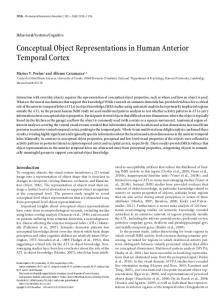
Figure 17 shows an extract of the Behavior Definition Diagram of a virtual robot in a manufacturing plant. For an actor, called Master, the behavior ProductionCycle is defined. It performs the following scenario of synchronized
Copyright Virtual Concept
Virtual Concept 2005
Conceptual Modeling of Object Behavior in a VE
movements. The object first moves forward, and then immediately some behaviors on its parts (LeftArmMovement and RightArmMovement) start, as well as a leftward movement. After the forward movement is ended, it turns right and this movement ends at the same time as the left movement. The diagram also shows a powerOn and a PowerOff behavior for a Control actor. These behaviors will move the Control and enable, respectively disable, the ProductionCycle behavior of the Master. These last actions are specified by means of the lifetime operators enable and disable.
actors RightArm and LeftArm the behavior RightArmMovement, respectively LeftArmMovement were defined (not shown here). These two behaviors are invoked by the ProductionCycle. Therefore, there are no events needed to trigger these behaviors. The Switch instance is given behavior by assigning the Control actor to it. As a consequence, this instance will have two behaviors PowerOn and PowerOff. In the diagram it is specified that both the PowerOn and the PowerOff behavior must be invoked by a timeEvent (at 9h00 for PowerOn and at 18h00 for the PowerOff). Lever:Switch (Control)
Master
PowerOn
09h00
18h00
ProductionCycle
forward (30°)
enable
PowerOn
PowerOff
right (90°) meets
Control forward (1.5m)
LeftArmMovement
ends
RobotArm:Gripper B (LeftArm)
ProductionCycle
PowerOff starts
left (0.5m)
RightArmMovement
disable
LeftArmMovement
RobotArm:GripperA (RightArm)
backward (30°)
RightArmMovement Robot:Assembler (Master) OnClick
Figure 18 : Behavior Invocation Diagram Figure 17 : Behavior Definition Diagram
69
After having defined the different behaviors, we can assign them to the objects defined for the Virtual Environment. This is done by means of the Behavior Invocation Diagram. Figure 18 shows such a Behavior Invocation Diagram. The Virtual Environment contains four object instances: an Assembler, a Gripper A, a Gripper B, and a Switch. The Master actor is assigned to the Assembler instance. Hence, the Assembler will possess the behavior defined for the Master actor (ProductionCycle). The diagram specifies that this behavior can be invoked by means of a user interaction (userEvent OnClick). This means that when the user “clicks” (e.g. by a mouse) on the Assembler this behavior will be executed. It is visually specified using a diamond connecting the behavior, the concept (or instance) and the event. If we now for example want to have another interaction triggering the behavior (e.g. in another situation), we can simply connect the object and behavior with a different event.
5- Tool Support and Integration in VR-DeMo
When the ProductionCycle behavior is attached to an object, also the behaviors that are causally linked (represented by the dashed arrows) to this behavior need to be assigned to objects. To assign behavior to Gripper A and Gripper B, the actors RightArm, respectively LeftArm are assigned to them. For the
For the purposes of this research, we have extended the prototype tool with the Conceptual Specification Generator (CSG). This is a graphical diagram editor supporting the modeling of the behavior as described. The tool has been implemented as an extension to Microsoft Visio [18]. The
-8-
In the previous section, we introduced the different modeling concepts for specifying 3D object behavior in Virtual Environments. This section now discusses tool support and gives an overview of the integration into the VR-DeMo project. 5.1 – Tool Support
To support the VR-WISE approach, we developed a prototype tool called OntoWorld. The tool enables a designer to make the conceptual design, specify the desired mappings and finally generate a VR application from the specifications as described in section 3. At the moment, only code in VRML/X3D formats is generated but in the future the tool can be extended to generate code for other implementation platforms as well.
Copyright Virtual Concept
Virtual Concept 2005
Conceptual Modeling of Object Behavior in a VE
static structure of the Virtual Environment as well as the behavior of its objects can be specified using the CSG. The graphical representations of the modeling concepts discussed in this paper can be dragged and dropped onto a canvas and connections can be made. Properties can be added, displayed and modified by double-clicking on the graphical representation. The CSG communicates with the previously developed OntoWorld tool. Consistency between the diagrams and the ontologies is maintained. The CSG can be considered as a graphical interface for the specification phase (first step in the VR-WISE approach).
behaviors modeled using the CSG. The Interaction module also generates C++ source code and a number of XML initialization files. The source code will be compiled and linked together with the third module, the Code Framework, into the run-time binary, implementing the VR application as described by the designer. The Code Framework is a repository that deals not only with the hardware but also with code libraries and provides the necessary support for the creation and manipulation of a scene graph, multimodal interaction, collision detection, etc.
Finally, the binary that is generated can be executed with the static scene and the scripts from the OntoWorld toolkit, and the initialization files from the Interaction toolkit as its input. 5.2 – Integration into VR-DeMo The interaction part is investigated by our research partner in The research presented in this paper is part of the VR-DeMo this project, the Expertise center for Digital Media (EDM) in project (Virtual Reality: Conceptual Descriptions and Models Belgium. for the Realization of Virtual Environments). The project aims at allowing designers to describe a complete Virtual Environment (the static structure, the behavior and the 6- Conclusion and future work interaction), at an abstract level that is much higher than programming code. The OntoWorld toolkit, as described in Our ultimate goal is to make the development of VR section 5.1, has been integrated into the VR-DeMo framework application available to a much broader public. We want to realize this by introducing an explicit conceptual design (given in figure 19). phase in the development process of a VR application. The use of a conceptual modeling phase with high-level modeling Conceptual Specification Generator concepts and in terms of domain concepts allows a better (CSG) participation of domain experts into the development of a VR application. In this paper we have introduced the modeling « communicates with » concepts developed for the specification of object behavior. « initialization » OntoWorld
Interaction Toolkit
« generates » Scene Graph (X3D)
« generates »
* ECMAScripts
* XML
XML
* Code (C++)
« initialization »
« source »
The behavior specification is split into two parts. In the first part, the behavior definitions are specified. Here, the use of actors allows us to define behavior independent of the actual objects that are going to perform the behavior and independent of the events that will trigger the behavior. In the second part, the behavior invocations are specified. In this part, the behaviors defined are assigned to the virtual objects. It also specifies how the behaviors can be triggered.
« produces » Run-time binary
Compiler
A prototype tool called OntoWorld was already created to support the overall approach. For the purpose of specifying behavior, we build a front-end in Microsoft Visio to allow creating the conceptual specification graphically. The graphical notation may seriously reduce the complexity of specifying the behavior in a Virtual Environment.
« linked with »
Code Framework
Figure 19 : Common Framework
The VR-DeMo framework mainly consists of three major modules: the OntoWorld tool with the CSG interface, the Interaction toolkit and the Code framework. The OntoWorld toolkit has already been described in section 5.1. It generates the scene graph (in X3D) together with the scripts used for the object behaviors and an additional XML initialization file. This initialization file will be used in the second module, the Interaction toolkit. This Interaction toolkit is concerned with the high-level modeling of the interaction and its connection to the object behaviors [19]. Here the modeling of menu systems and dialog boxes can be done. These can then be used to trigger the
69
-9-
Future work will focus on extending the current set of modeling concepts. For example, the modeling of physics, to obtain applications with a higher degree of physical correctness, will be investigated. We will also investigate how to model, at a high level, constraints on behavior.
7- Acknowledgements
This research is carried out in the context of the Ontobasis and the VR-DeMo project; both projects are funded by the Institute for the Promotion of Innovation by Science and Technology in Flanders (IWT). It is also partially funded by the FWO (Fund of Scientific Research – Flanders).
Copyright Virtual Concept
Virtual Concept 2005
Conceptual Modeling of Object Behavior in a VE
[16] Valente A. and Breuker J. Towards principled core ontologies. In Proceedings of the Tenth Knowledge [1] Rohlf J. and Helman J. IRIS Performer: A High Acquisition for Knowledge-Based Systems Workshop, Performance Multiprocessing Toolkit for Real--Time 3D Alberta, Canada, pp. 301-320, 1996 st Graphics. In Proceedings of the 21 annual conference on Computer Graphics and Interactive Techniques, Orlando - [17] Allen J.F. Maintaining Knowledge about Temporal Intervals. In Communications of the ACM, 26(11):832-843, Florida USA, pp. 381-395, 1994 1983 [2] Murdock K.L. 3DS Max 5 Bible. Wiley Publishing [18] Walker M., Eaton N.J. and Eaton N. Microsoft Office Incorporated, 2003 Visio 2003 Inside Out. Microsoft Press, 2003 [3] Ames A.L., Nadau D.R. and Moreland J.L. VRML 2.0 [19] Raymaekers C., Coninx K., De Boeck J., Cuppens E. Sourcebook. John Wiley & Sons Inc., 1997 and Flerackers, E. High-level Interaction Modelling to [4] Bille W., Pellens B., Kleinermann F. and De Troyer O. Facilitate the Development of Virtual Environments. In Intelligent Modelling of Virtual Worlds Using Domain Proceedings of Virtual Reality International Conference, Ontologies. In Proceedings of the Workshop of Intelligent Laval, France, pp. 81-86, 2004 Computing (WIC), Mexico City - Mexico, pp. 272-279, 2004 8- References
[5] Gruber T.R. A translation approach to portable ontologies. In Journal of Knowledge Acquisition, 5(2):199-220, 1993 [6] Guarino N. and Giaretta P. Ontologies and knowledge bases: towards a terminological clarification. In Towards Very Large Knowledge Bases: Knowledge Building Knowledge Sharing, N.J.I. Mars (ed.), IOS Press, Amsterdam, The Netherlands, pp. 25-32, 1995 [7] Tanriverdi V. and Jacob R.J.K. VRID: A Design Model and Methodology for Developing Virtual Reality Interfaces. In Proceedings of ACM Symposium on Virtual Reality Software and Technology, Alberta, Canada, pp. 175-182, 2001 [8] Kim G.J., Kang K.C., Kim H. and Lee J. Software Engineering of Virtual Worlds. In Proceedings of the ACM Symposium on Virtual Reality Software & Technology ’98, Taipei, Taiwan, pp. 131-139, 1998 [9] Willans J.S. Integrating behavioural design into the virtual environment development process. Phd thesis, University of York, UK, 2001 [10] Willans J.S. and Harrison M.D. A toolset supported approach for designing and testing virtual environment interaction techniques. In International Journal of HumanComputer Studies, 55(2):145-165, Academic Press, 2001 [11] Fishwick P., Lee J., Park M. and Shim H. RUBE: a customized 2d and 3d modeling framework for simulation. In Proceedings of the 35th conference on Winter simulation: driving innovation, New Orleans, Louisiana, pp. 755-762, 2003 [12] Lee G. A., Kim G. J. and Park C. Modeling Virtual Object Behavior within Virtual Environment. In Proceedings of ACM Symposium on Virtual Reality Software and Technology (VRST), Hong Kong, China, pp. 41-48, 2002 [13] Kallmann M. and Thalmann D. Modeling Behaviors of Interactive Objects for Virtual Reality Applications. In Journal of Visual Languages and Computing, 13(2):177-195, 2002 [14] Huang Z., Eliens A. and Viseer C. Implementation of a scripting language for VRML/X3D-based embodied agents. In Proceedings of the Web3D 2003 Symposium, Saint Malo, France, S. Spencer (ed.) ACM Press, pp. 91-100, 2003 [15] De Troyer O., Bille W., Romero R. and Stuer P. On Generating Virtual Worlds from Domain Ontologies. In Proceedings of the 9th International Conference on Multimedia Modeling, Taipei, Taiwan, pp. 279-294, 2003
69
-10-
Copyright Virtual Concept