Sep 5, 2013 - possible development of a lab-on-chip for point-of-care blood analysis ..... fluorescence microscope (IX71, Olympus Inc.) equipped with a 12-bit ...
BIOMICROFLUIDICS 7, 054101 (2013)
Continuous separation of blood cells in spiral microfluidic devices Nivedita Nivedita and Ian Papautskya) BioMicroSystems Lab, School of Electronic and Computing Systems, University of Cincinnati, Cincinnati, Ohio 45221, USA (Received 15 June 2013; accepted 9 August 2013; published online 5 September 2013)
Blood cell sorting is critical to sample preparation for both clinical diagnosis and therapeutic research. The spiral inertial microfluidic devices can achieve label-free, continuous separation of cell mixtures with high throughput and efficiency. The devices utilize hydrodynamic forces acting on cells within laminar flow, coupled with rotational Dean drag due to curvilinear microchannel geometry. Here, we report on optimized Archimedean spiral devices to achieve cell separation in less than 8 cm of downstream focusing length. These improved devices are small in size (90% WBCs enrichment, but the trapezoidal cross-section has complicated fabrication process which requires that the master for PDMS (polydimethylsiloxane) casting be milled rather than patterned on a wafer. In this work, we describe optimized spiral devices with reduced size and improved performance for separation of blood cells from plasma, as well as separation of WBCs and RBCs. Previous spiral designs had a focusing length of 40 cm with an inner radius of 1 cm which resulted in a large device footprint (�3 in2).18,19 These devices were designed with the assumption that De (Dean number) is constant over the length of the spiral, which is not the case with spirals as there is a continuous change in radius of curvature that leads to progressive decrease
054101-3
N. Nivedita and I. Papautsky
Biomicrofluidics 7, 054101 (2013)
in De. The optimized spiral designs are not only 10� smaller in size as compared to our previous design18 but also provide higher efficiency (>95%) and throughput (1–2 ml/min). The reduced form factor and the low-aspect ratio nature make these devices more amenable to integration with lab-on-chip systems and to fabrication by high-throughput techniques such as rollto-roll processing.34 MECHANICS OF SORTING
Sorting cells in rectangular microchannels is dependent on the intricate balance of hydrodynamic forces. Shear gradient arising from parabolic velocity profile of Poiseuille flow induces inertial lift forces (FIL) that cause cells or neutrally buoyant microparticles to migrate towards channel walls. As they migrate closer to channel walls, they are repelled away from walls towards the channel center due to wall induced lift forces (FWL). This is schematically illustrated in (Fig. 1(a)).16,17,23–25,38 The balance of the two opposing forces causes particles to equilibrate at �0.2Dh (where hydraulic diameter Dh ¼ 2hw/(h þ w), where w is the width of the channel and h is the height of the channel). This balance has been observed in rectangular channels when the particle diameter ap is sufficiently large relative to the microchannel crosssection (ap/Dh > 0.07). The equilibrated particles form ordered streams around the channel periphery in four positions at wall centerlines for square channels.16,17,23–25,38 While the balance of the two lift forces can successfully explain particle focusing in a capillary, square and rectangular microchannels present a more complex situation due to radial asymmetry. Since the shear-induced lift causes particles to migrate away from the channel center, down the shear gradient toward the channel wall, one would expect particles to equilibrate along the perimeter of the channel (including corners) to achieve force balance. However, work in microfluidic channels has identified four distinct focusing positions centered at each face in square microchannels.24 The absence of particles in corners suggests that additional lateral migration effects take place near channel walls that cause particle migration toward wall centers. Indeed, a rotation-induced lift force FX was proposed in the early work by Saffman40 and recently confirmed
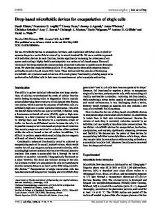
FIG. 1. (a) Schematic illustrating the behavior of particles in a straight rectangular channel. (b) Fluorescent image of the cross-section of the spiral channel showing the formation of counter rotating vortices when fluorescein is injected along with DI water to detect the presence of Dean Vortices. (c) Schematic illustrating the effect of curvature on the focusing positions. Larger particles focus in a single position closer to the inner channel wall and an appropriate outlet system can enhance the collection of the particles/cells sorted according to their sizes. (d) Intensity plot of 20 lm diameter particles across the width of the channel at the end of each loop in the spiral (loop 1 being the inner-most loop and loop 4 being the outer-most). The two inset figures show the fluorescent images of the 20 lm polystyrene particles at the inner most loop (loop 1) of the spiral device (500 lm � 110 lm) and at loop 4 focused in a single stream near the inner channel wall.
054101-4
N. Nivedita and I. Papautsky
Biomicrofluidics 7, 054101 (2013)
by Zhou et al.38 While negligible away from the wall, FX is significant at the channel wall and explains the asymmetric equilibrium positions in rectangular microchannels. The introduction of a rotation-induced lift force leads to a more complex model of inertial migration at finite Re. Both shear and wall induced lift forces dominate particle migration toward channel walls. Once the initial equilibrium is reached, near channel walls particle motion is dominated by the rotation-induced lift force. As a result, particles migrate to the center points of walls. This two-stage model of inertial focusing developed by Zhou et al.38 is generally applicable to rectangular microchannels of any aspect ratio at finite Re, and can be used to aid the design of inertial microfluidic systems. In spiral microchannels, curvature-induced secondary flows—Dean vortices—act to disrupt the focusing by hydrodynamic forces. The first conclusive analysis of flow in curved channels was done by Dean in 1927, who showed that in curved channels the plane Poiseuille flow is disturbed by the presence of centrifugal force (FCF), causing flow instability and shifting the maximum velocity point from the channel center towards the concave channel wall.26,27 This gives rise to Dean instability which leads to the development of a secondary, vortex flow from the concave wall to the convex wall of the channel (Fig. 1(b)). The Dean vortices are characterized by the Dean number De, which indicates the strength of secondary flows in curved channels and directly represents the Dean force due to secondary flows in these curved channels.18,24,26–30 It is defined as De ¼ Re(Dh/2R)0.5, where Re is the Reynolds number and R is the radius of the curvature of the convex surface of the curved channel. Hence, the strength of the secondary flow is strongly dependent on the dimensions of the channel, the radius of curvature, and the flow velocity. From this definition of the De, the most effective way of controlling the Dean flows is through the Dh, since it scales as De / Dh1.5. Another approach is to introduce a tighter curvature with lower R, since De scales inversely to change in R. However, it is difficult to vary microchannel dimensions post fabrication, and thus, the most practical approach is to vary the input flow (i.e., flow Re). Next, we will consider interaction of the inertial lift forces with the Dean force in spiral microchannels. A cell suspended in a spiral microchannel experiences a transverse Dean drag force due the two major Dean vortices and the inertial lift forces due to the rectangular cross section. Assuming Stokes drag, the Dean force FD experienced by the cells or particles while travelling through a spiral channel is given by FD ¼ 3plUD ap ¼ 5:4 � 10�4 plDe1:63 ap , where UD is the average Dean velocity (UD ¼ 1.8 � 10�4 De1.63), ap is the diameter of the particle, and l is the viscosity of the fluid.9,10,14,15 Since most of the spiral devices use low aspect ratio channels, the rotational lift force can be neglected and it can be assumed that the inertial focusing stays in transition between first and second stages of the two stage migration model in straight channels with the net lift force (FL) defined as FL ¼ qG2 CL ap 4 , where CL is the lift co-efficient and G is the shear rate dependent on flow velocity and characteristic length. The scaling of FL is highly dependent on whether the lift co-efficient is constant or scaling with particle/cell size. Recently, Zhou et al.38 have experimentally showed that in high aspect ratio channels CL / ap�2, which leads to FL / ap2. But, in case of low aspect ratio spiral channels, CL can be considered a constant since the Dean vortices push particles/cells towards channel walls. The ratio of the inertial lift and Dean drag forces is strongly dependent on cell size, scaling as FL/FD / CL ap3. Thus, the magnitude of the Dean force provides mechanisms to adjust the focusing position and the focusing length for the particles. The two major counter-rotating Dean vortices in a spiral microchannel can then be used to manipulate the focusing position of the cells. These vortices displace the cells from the multiple focusing positions due to the imbalance between the net Dean force and the net lift force. The result is that cells focus in a single stream near the inner channel wall depending on their size, with the largest focusing closest to the inner wall (Fig. 1(c)).18,24 This size dependence of the ratio of inertial lift forces and Dean drag forms the basis of the design of spiral devices for size-based separation of particles and cells. Fig. 1(d) illustrates focusing in a 500 lm � 100 lm Archimedean spiral microchannel. The fluorescent intensity line-scan indicates the progressive focusing of a sample containing 20 lm diameter polystyrene
054101-5
N. Nivedita and I. Papautsky
Biomicrofluidics 7, 054101 (2013)
particles. At 900 ll/min flow rate, it was observed that the particles focus in a tighter stream, almost a single-particle stream by the time the particles reach loop 4. The calculated FWHM (full width at half maximum) at loop 1 was �340 lm which indicates distribution of the particles almost across the entire width of the channel. As particles move downstream, they experience Dean drag along with the inertial lift forces causing progressive focusing closer to the inner channel wall. By loop 4, the FWHM reduces to �24 lm indicating focusing in a single stream, one particle after the other. As particles focus in a single stream near the inner channel wall, with the largest being closest to it, an outlet system can be used to collect the separated particles. EXPERIMENTAL METHODS
Microchannels were fabricated in PDMS (Sylgard 184, Dow Corning) using the conventional soft lithography process. Masters 75–110 lm thick were formed in SU-8 photoresist (2075, Microchem Corp.). A mixture of PDMS base and curing agent (10:1 ratio) was cast on masters and cured for 4 h on a 60 � C hotplate. Cured PDMS devices were peeled off, and inlet/outlet ports were punched with a 14 gauge syringe needle. PDMS was bonded to standard glass slide using a hand-held plasma surface treater (BD-20AC, Electro-Technic Products Inc.). Two fabricated designs included a three outlet system with a 250 lm � 75 lm channel cross-section (design 1) and a four outlet system with a 500 lm � 110 lm channel cross-section (design 2). To demonstrate device performance, fluorescently labeled polystyrene particles 7.32, 10, 15, and 20 lm in diameter (Bangs Laboratories) were used. A particulate mixture at 0.1% volume fraction was used at flow rates 0.07.15,18,19,24 These data are calculated for Re ¼ 100, leading to a general optimization for the particles satisfying the aforementioned conditions. The design equations can be formulated based on the empirical data and the optimization results. The optimal length of focusing of particles satisfying the ap/Dh condition was then found to be dependent on the gradient of the change in De along the length of the spiral. For each of the two designs, we obtained the following differential equations describing the dependence of the variation of the De number on the length downstream
FIG. 2. (a) Optimization results for design 1 (250 lm � 75 lm). Dean number decreases as b (0.159, 0.0795) increases, although there is not much change in the order of the curve, except for the amplitude. The residual for each case is denoted by the dotted plot of the respective color. The point of zero residual gives the approximate focusing length required for forming a spiral with initial radius, a ¼ 2 mm and the given dimensions of the rectangular channel. (b) Optimization results for design 2 (500 lm � 110 lm). b for this device is taken similar to the one taken for the previous device. The change in cross-section changes the hydraulic diameter, thereby changing the order of the exponential decrease in the Dean number with respect to increase in downstream length.
054101-7
N. Nivedita and I. Papautsky
Biomicrofluidics 7, 054101 (2013)
� � �� @De �2:39 x�1:136 ; ¼ �3:55 x�1:171 @x
(1)
where De is the Dean number and x is the downstream length of the spiral. Equation (1) was derived from the experimental data of Figs. 2(a) and 2(b). We used MS Excel to fit data, analyse regression co-efficients (2.39, 3.55), and determine mathematical expressions describing the data trends for the 2 different designs. A common design equation was then empirically formulated to suit the two cases. Solving the differential equations, we obtain a single design equation which describes downstream length of the spiral (x) required to focus the cells or particles for an optimized Dean number Deop Deop ¼ 3:5
Lm �LDh x m; Dh
(2)
where Lm is the Dean migration length. Dean migration length is the maximum distance the particle has to travel to reach closer to the inner channel wall and reach the equilibrium position. Lm ¼ W þ H þ 3/4 W, where H is the height of the channel and W is the width of the channel. Cells of larger size require a shorter downstream length to focus as compared to cells of smaller size. The focusing length of the particles in a spiral microchannel can be calculated from Eq. (2) by adjusting the optimized Dean number. Any increase in spacing between the channels decreases the Dean number, thereby increasing the focusing length for the particle. If s (spacing between the adjacent channel center-line) is kept constant, change in the width of the channel accordingly modifies the rate of the exponential decay in the Dean number with respect to the downstream length. The focusing length is the point at which the residual is determined to be either equal to or less than zero. Residual is the difference between the focusing length calculated with the assumption that the radius is constant at that particular point and the circumference/total length of the spiral arc using the same radius. Since both the constant-radius focusing length and the circumference/arc change in length at each point in the spiral due to the progression in the radius of curvature, the point at which the difference between the two is zero determines the actual focusing length. For separation of blood cells from plasma, we used the 250 lm � 75 lm device with a spacing of 250 lm between the loops and focusing length of �6 cm. Although the platelets do not quite meet the ap/Dh criterion for focusing, yet, we selected this specification for the device as it should at least result in partial focusing of the platelets. For separation of WBCs and RBCs, a broader channel with a longer focusing range was needed to focus cells into distinct streams, within the length of the spiral. To achieve that, we used 500 lm � 110 lm devices with a spacing of 500 lm between the loops (more convenient for soft-lithography process) and the focusing length of �8 cm. The focusing length determines the total length of the channel when unwound from its spiral coil into a straight channel. This length also determines the number of loops a spiral device will need to have in order to accommodate the required length for cell-focusing. Hence, focusing length is the key factor in determining the total size of the device if the size of the inlets and outlets are fixed. Compared to the previous Archimedean spiral devices, we have reduced the focusing length �5� and reduced the device area 10�. This substantial decrease in size allows the ease of fabrication of these devices using fabrication techniques other than soft lithography (PDMS devices). The reduced size of these devices makes them amicable to fabrication by large-scale manufacturing methods such as roll-to-roll processing.31 Indeed, we have successfully fabricated these devices in PET and PMMA in collaboration with VTT Technical Research Centre of Finland using this approach. Ultimately, this could lead to inexpensive, disposable devices. Device characterization
The developed devices were characterized using neutrally buoyant fluorescently labeled polystyrene particles (Polysciences, Inc.). Since the sorting mechanism is dependent on the size
054101-8
N. Nivedita and I. Papautsky
Biomicrofluidics 7, 054101 (2013)
of the cell/particles in the flow stream, we used particles with diameters similar to the blood cells. The flow parameters were optimized by injecting polystyrene particles �7.32, 10, 15, and 20 lm in diameter (1.6 � 105 particles/ml) at flow rates of 1-3 ml/min. The Dean number was calculated using the input Re and Dh values (width and height for Dh calculation were measured post fabrication) since the microchannel cross-section is constant. The radius of the curvature, R was measured from the center to the inner-most wall at every 30� interval on each of the loops. When particle mixture was injected at 1 ml/min in design 1 device, all particles focused into a broad band near the inner channel wall. At the outlet bifurcation, they all followed the flow, eluting in outlet 1 (Fig. 3). As the size of RBCs and WBCs is in the range of sizes of particles, it was concluded that this device not only provides the confirmation of the hypothesis for isolation of blood cells from plasma but also shows that this separation may be accomplished with a high level of efficiency (�100%). Next, we characterized design 2 devices for sorting RBCs and WBCs. The devices based on design 2 focused particles into two streams at a constant flow rate of 1.8 ml/min. The particles in the broad stream (10, 15, 20 lm) eluted in the first outlet and the particles from the narrow stream, closer to the center of the channel, eluted in the second and third outlet (Fig. 4). Further increase in the flow rate to 2.2 ml/min disrupted the focusing of 7.32 lm diameter particles, but further focused the particles in the broad stream into three distinct streams of 10, 15, and 20 lm diameter particles with 20 lm diameter particles focused closer to the inner channel wall. These results further emphasize that the equilibrium position of the focused cells is strongly dependent on their size, as well as flow properties and channel geometry. These results also show that by maintaining proper flow conditions and a four outlet pattern, RBCs, which are �7 lm in diameter, should elute in the second and third outlets and WBCs, which are in the range of 10-20 lm, should elute in the first outlet of the device. After determination of optimal conditions and definitive flow parameters, the devices were tested with blood. Approximately 10 ml of male whole blood sample (45% hct) was provided by Hoxworth Blood Center (University of Cincinnati Academic Health Center). Since blood is a viscous, non-Newtonian fluid, behavior of blood cells does not follow to that of particles as determined during the optimization experiments. Hence, to work with blood, it was necessary to first evaluate the effect of blood dilution on separation efficiency in our microchannels. Blood dilution
Blood rheology affects the functionality and efficiency of all passive microfluidic sorting devices based on hydrodynamic forces acting on the cell-components of blood. Blood is a nonNewtonian fluid and the viscosity is highly dependent on hematocrit, plasma protein concentration, platelet count, and leukocyte count. The plasma concentration also affects the cell to cell interaction in blood.1,32 In passive microfluidic devices which are based on hydrodynamic
FIG. 3. (a) Image of design 1. (b) Bright-field image of the outlet system. (c) A mixture of 7.32 lm, 10 lm, 15 lm, and 20 lm diameter fluorescently labeled particles is injected at the flow rate of �1 ml/min in the device. (d) Almost all the particles focus in a broad stream near the inner channel wall eluting in outlet 1. (e) Flow cytometer results for the particles collected at the outlets.
054101-9
N. Nivedita and I. Papautsky
Biomicrofluidics 7, 054101 (2013)
FIG. 4. (a) Image of design 2. (b) Bright field image of the outlet system. (c) At 1.8 ml/min flow rate (F1), two focused streams are observed, the narrow stream in the middle of the channel is formed by 7.32 lm particles and the broad stream near the inner channel wall is the composite of three streams of 10, 15, and 20 lm particles. Particles in the range of 10–20 lm are obtained out of the first outlet, and the 7.32 lm particles are obtained from the second and third outlets. (d) Fluorescent image of the focused streams of all three particles, 10 lm, 15 lm, and 20 lm in diameter, at the flow rate of 2.2 ml/min (F2). (e) Normalized focusing position of particles (x is the distance of the focused stream from the inner channel wall, and w is the width of the channel) as function of De.
forces acting in a Newtonian, poiseuille flow, blood is required to be diluted for the forces to be strong enough to cause cell-separation.1,32 Spiral microchannels not only depend on hydrodynamic forces but also on dean vortices to effectively sort cells according to their size. Although the shear induced lift force and wall induced lift force are dependent on the parabolic velocity profile and Newtonian nature of the fluid to cause cell-separation, dean vortices are known to act in highly viscous fluids with vortex formation. This differential effect of blood rheology on the dean vortices and hydrodynamic forces affects the sorting efficiency and throughput in spiral microchannels. Although the secondary flows manifest themselves in viscous fluids, their amplitude and point of instability and balance with inertial lift forces are not as well defined when optimizing the devices using particle experiments. Also, the neutral buoyancy of cells and cell to cell interaction poses a significant contention to the sorting ability of the optimized devices. To test the particle behavior as a function of blood-dilution, whole blood was diluted 10� to 700� (4.5% hct to 0.07%) with 0.9% saline solution, and each sample was used in both devices. The width of the focusing streams of cells was observed at each dilution (Fig. 5(a)). To determine the sorting efficiency, the samples collected at the outlets (in 2 ml vials) were centrifuged at 1000 rpm for 10 min. The centrifuged samples were stained with Wright-Geimsa stain to identify the type of cells collected. The staining was done as per the standard procedure of the use of the WGstain. The stained cells were then counted using hemocytometer. At 10–20� dilution, the sheer concentration of cells overwhelms the focusing position of cells. It is clear that higher the dilution better is the focusing of the cells along with precise extraction of the separated cells. Fig. 5(a) shows the effect of dilution on focusing of the cells in a 250 lm � 75 lm spiral channel. The plot in Fig. 5(a) describes the width of the focused cells near the inner channel wall for each dilution at 1 ml/min flow rate proving the assumption that lower dilution provides more precise focusing. The higher dilution causes blood to behave like Newtonian fluid and it also prevents cell to cell interaction providing better focusing (Fig. 5(b)). The separation efficiency is shown to increase with dilution especially in the case of separation of RBCs and WBCs, as stronger inertial force is required for precise size-based separation. Although at lower dilution, RBC-RBC interaction is still observed in the form of cells bouncing off of each other especially due to cell concentration, the spacing between the focused streams is not disrupted and the efficiency of sorting is not compromised. Although the lateral force generated by cell deformability of RBCs may cause the broadening and pulsation of the focused band of RBCs since deformability may cause cells to elongate within the flow leading to change in focusing positions depending on whether the cells are focusing along the shorter axis or longer axis. These results are in agreement with the work done by Toner et al.,32 who showed decrease or shift in
054101-10
N. Nivedita and I. Papautsky
Biomicrofluidics 7, 054101 (2013)
FIG. 5. (a) Bright Field images of blood cells focused in the outermost loop of an Archimedean spiral (250 lm � 75 lm) with 10, 50, 100, and 200 fold dilution. (b) A log-plot of normalised width of the focused stream (d is the width of the focused stream and w is the width of the channel) with the dashed curve defining the plot for design 1 and the solid curve defining the plot for design 2. (c) Plot of separation efficiency of extraction of plasma in 250 lm � 75 lm spiral device as a function of dilution of the whole blood.
focusing of polystyrene particles, WBCs and PC-3 cells with change in the volume fraction in the blood sample from 1 (45% hct) to 0.07 (3.15% hct). Although plasma extraction is possible at low dilution, higher efficiency of separation in case of RBCs (Fig. 5(c)) and WBCs is only possible at higher dilution (�500�). Plasma extraction
Following the determination of the flow parameters required for the separation and appropriate dilution, the 100� diluted blood (0.45% hct) was injected into the devices with design 1 at a constant flow rate of �1 ml/min. It was observed that no cells eluted in outlet three, showing that the third outlet provided us with cell-free plasma. The first and second outlets, however, had all the RBCs, WBCs, and platelets eluting from it. Figs. 6(a)–6(c) show stained cells at the inlet of the spiral device, cells collected at the 1st and 2nd outlet and plasma collected at the 3rd outlet. Fig. 6(d) shows the focusing of cells in a broad stream near the inner channel wall at the outer-most loop of the device. Although it was observed that cells bounce off of each other, their net movement was along the focused stream and this did not compromise the sorting efficiency. We surmise that this cell to cell interaction is more relevant in case of lower dilution due to sheer overwhelming of cells at the focusing positions. In this case, however, the focused streams of cells with different sizes are close together such that they form a broad, visible band of focused cells, all eluting in the same outlet. The cell to cell interaction is not strong enough to modify or disrupt the focusing of cells near the inner channel wall. This device provides �100% cell-free plasma from the 100� diluted blood (0.45% hct). It is possible to
054101-11
N. Nivedita and I. Papautsky
Biomicrofluidics 7, 054101 (2013)
FIG. 6. (a) Bright-field image of blood cells distributed throughout the width of the channel at the inlet of design 1. Arrows indicate the white blood cells. (b) All the cells, including platelets elute in the 1st and 2nd outlet. (c) No cells are obtained, only plasma from outlet 3. (d) Bright field image of the cells focused in a broad stream near the inner-channel wall, thereby eluting in the first and second outlet. Samples collected from each outlet were centrifuged and then stained and observed.
achieve higher efficiency at lower dilution (�50�) by suitable modification of the outlet system. At 0.9% hct, we achieved �90% 6 3% efficiency, which is equivalent to plasma extraction at the rate of 20 ll/min of whole blood (45% hct). The efficiency and throughput is significantly higher than other plasma extraction techniques like the passive microfluidic device used for plasma extraction by Sollier et al.33,34 with 17% extraction yield with 1:20 dilution, Electro-osmotic flow controlled device used by Jiang et al.35 which yielded 26% efficiency and two phase plug flowing through disposable tubing technique by Sun et al.36 with 10� diluted blood yielding efficiency of �64% in 1 ll plug. Even the most common technique of centrifugation is extremely prone to contamination while extraction of plasma from whole blood. Blood cell sorting
To sort the RBCs and WBCs, the 500� diluted blood sample (�0.1% hct) was run through design 2 devices at 1.8 ml/min to ensure lower cell to cell interaction and higher effects of inertial lift forces and dean vortices. It was observed that the WBCs focused closer to the inner channel wall owing to their larger size and RBCs focused closer to center of the channel, allowing the collection of the cells by the use of the four outlet system. The cells at each outlet were collected, centrifuged, stained, and counted using a hemocytometer. Cells collected from the first outlet had 95% 6 2.2% of WBCs and 6% 6 2.4%of RBCs, with a few platelets (Fig. 7(b)). This corroborated the results from the particle experiments where the 10, 15, and 20 lm diameter particles eluted in the first outlet. WBCs being in the range of 10–20 lm focused closer to the inner channel wall and eluted in the first outlet. The sample collected from the second and third outlet had 94% 6 2.5% RBCs (Fig. 7(c)). The fourth outlet had only platelets floating in diluted pale yellow liquid or plasma. The hemocytometer counts confirmed the separation efficiency of �95% 6 3%, with a high throughput (�107 RBCs/ml and �105 WBCs/ml), as shown in Fig. 8. This translates to a throughput of �3.6 ll/min of whole blood (45% hct) which is comparable to the recent blood sorting work by Han et al.43 where they showed >90% efficiency of enrichment of WBCs. Although platelets could not be separated, there is an almost complete separation of leukocytes and erythrocytes. This is significantly higher than the leukocyte extraction by dielectrophoretic (DEP) microseparator37 which had efficiency of 92%, but throughput of 0.8 ll/min, hydrodynamic filtration14 with 29� enrichment of leukocytes with a throughput of 20 ll/min with 10� dilution of whole blood and leukocyte extraction using magnetophoresis6,7 with
054101-12
N. Nivedita and I. Papautsky
Biomicrofluidics 7, 054101 (2013)
FIG. 7. (a) Bright field images of the stained samples after they were collected from each outlet of the design 2 and centrifuged. Inlet has all the cells present. Arrows indicate the white blood cells. (b) Outlets 2 and 3 have RBCs and platelets. (c) Outlet 1 has majority of WBCs (Neutrophils, Eosinophil, and Monocyte), some platelets and very little RBCs, and (d) outlet 4 has only diluted plasma and platelets
efficiency of 97%, but throughput is 0.04 and 0.33 ll/min. Further, since the throughput and efficiency was calculated using only the viable cells collected at the outlets, the throughput is indicative of cell viability. As such blood cells are quite robust as shown in the previous work by Toner et al.1 and Han et al.43 CONCLUSIONS
In this work, we successfully demonstrated continuous separation of erythrocytes and leukocytes from a diluted sample of blood. Due to high separation efficiency (�95%) and high throughput (1–2 ml/min of �0.1 hct), these spiral microfluidic devices offer a label-free alternative to a key step in CBC analysis. These devices solve the issue of trade off which has been
FIG. 8. Hemocytometer results with normalized cell count at each outlet showing �90% efficiency of separation of RBCs from WBCs.
054101-13
N. Nivedita and I. Papautsky
Biomicrofluidics 7, 054101 (2013)
faced by earlier microfluidic devices along with providing label-free sorting which has been difficult to achieve especially in case of active devices.5–8,37 The considerable reduction in size allows these devices to be integrated with on-chip blood-cell analysis or plasma analysis systems without any sample contamination or sample loss. These passive devices provide both higher sorting efficiency and higher throughput as compared to microfluidic sorting techniques like microfluidic filtration and magnetophoretic devices and hence can be used as a sorting platform for point of care blood-analysis devices. Further optimization of these devices can enable a WBC differential with minimal sample volume and on integration with an on-chip cell-counter, can potentially provide a CBC-on-chip. Other spirals have also been used for cancer stem cell sorting as shown by Sun et al.41 with �90% efficiency. Hence, our design which has the ability to sort cells with size in the same range could possibly be used for other, more sizeselective applications like cancer stem cell sorting. Blood dilution is one of the challenges that need to be further addressed. Although >100� dilution was used in the experiments discussed, blood dilution can be as low as 20� if very high efficiency of sorting is not a requirement. This option of variable dilution allows the use of these devices in not only commercial but also laboratory platform. Due to passive mechanism of separation, simple planar structure and low cost these devices are easy to use and are disposable. Ultimately, these devices offer a pathway towards development of a “blood-on-achip” point-of-care system with high efficiency, low cost, and reduced analysis time. ACKNOWLEDGMENTS
We gratefully acknowledge partial support by the Defense Advanced Research Projects Agency (DARPA) N/MEMS S&T Fundamentals Program under Grant No. N66001-1-4003 issued by the Space and Naval Warfare Systems Center Pacific (SPAWAR) to the Micro/nano Fluidics Fundamentals Focus (MF3) Center.
1
M. Toner and D. Irimia, Annu. Rev. Biomed. Eng. 7, 77 (2005). See http://labtestsonline.org/understanding/analytes/cbc/test.html for significance of blood cells and complete blood count. 3 See http://www.pall.com/main/medical/blood-separation-and-centrifugation-52896.page for details on centrifugation for plasma and blood cell sorting. 4 A. L. Givan, Flow Cytometry: First Principles (John Wiley and Sons, Inc., New York, 2008). 5 N. Pamme and A. Manz, Anal. Chem. 76, 7250 (2004). 6 M. Zborowski, G. R. Ostera, L. R. Moore, S. Milliron, J. J. Chalmers, and A. N. Schechter, Biophys. J. 84, 2638 (2003). 7 K. Han and A. B. Frazier, Lab Chip 6, 265 (2006). 8 M. D. Vahey and J. Voldman, Anal. Chem. 80, 3135 (2008). 9 N. Pamme, Lab Chip 7, 1644 (2007). 10 A. A. S. Bhagat, H. Bow, H. W. Hou, S. J. Tan, J. Han, and C. T. Lim, Med. Biol. Eng. Comput. 48, 999 (2010). 11 S. K. Murthy, A. Sin, R. G. Tompkins, and M. Toner, Langmuir 20, 11649 (2004). 12 L. R. Huang, E. C. Cox, R. H. Austin, and J. C. Sturm, Science 304, 987 (2004). 13 M. Yamada, M. Nakashima, and M. Seki, Anal. Chem. 76, 5465 (2004). 14 M. Yamada and M. Seki, Lab Chip 5, 1233 (2005). 15 A. A. S. Bhagat, S. S. Kuntaegowdanahalli, and I. Papautsky, Lab Chip 8, 1906 (2008). 16 D. Di Carlo, J. F. Edd, D. Irimia, R. G. Tompkins, and M. Toner, Anal. Chem. 80, 2204 (2008). 17 D. Di Carlo, D. Irimia, R. G. Tompkins, and M. Toner, Proc. Natl. Acad. Sci. U.S.A. 104, 18892–18897 (2007). 18 S. S. Kuntaegowdanahalli, A. A. S. Bhagat, G. Kumar, and I. Papautsky, Lab Chip 9, 2973 (2009). 19 A. A. S. Bhagat, S. S. Kuntaegowdanahalli, and I. Papautsky, Microfluid. Nanofluid. 7, 217 (2009). 20 Z. Wu, B. Willing, J. Bjerketorp, J. K. Jansson, and K. Hjort, Lab Chip 9, 1193 (2009). 21 J. Oakey, R. W. Applegate, E. Arellano, D. D. Carlo, S. W. Graves, and M. Toner, Anal. Chem. 82, 3862 (2010). 22 J. Seo, M. H. Lean, and A. Kole, Appl. Phys. Lett. 91, 033901 (2007). 23 E. S. Asmolov, J. Fluid Mech. 381, 63 (1999). 24 A. A. S. Bhagat, S. S. Kuntaegowdanahalli, and I. Papautsky, Phys. Fluids 20, 101702 (2008). 25 R. Eichhorn and S. Small, J. Fluid Mech. 20, 513 (1964). 26 W. R. Dean, Philos. Mag. 5, 673 (1928). 27 W. R. Dean, Philos. Mag. 4, 208 (1927). 28 P. M. Ligrani, J. E. Longest, M. R. Kendall, and W. A. Fields, Exp. Fluids 18, 41 (1994). 29 P. M. Ligrani and R. D. Niver, Phys. Fluids 31, 3605 (1988). 30 A. P. Sudarsan and V. M. Ugaz, Lab Chip 6, 74 (2006). 31 R. Liedert, L. K. Amundsen, A. Hokkanen, M. M€aki, A. Aittakorpi, M. Pakanen, J. R. Scherer, R. A. Mathies, M. Kurkinen, S. Uusitalo, L. Hakalahti, T. K. Nevanen, H. Siitari, and H. S€ oderlund, Lab Chip 12, 333 (2012). 32 E. J. Lim, T. J. Ober, J. F. Edd, G. H. McKinley, and M. Toner, Lab Chip 12, 2199 (2012). 2
054101-14 33
N. Nivedita and I. Papautsky
Biomicrofluidics 7, 054101 (2013)
E. Sollier, M. Cubizolles, M. Faivre, Y. Fouillet, and J. L. Achard, Conf. Proc. IEEE Eng. Med. Biol. Soc. 2009, 7030–7033. E. Sollier, M. Cubizolles, Y. Fouillet, and J. Achard, Biomed. Microdevices 12, 485 (2010). 35 H. Jiang, X. Weng, C. H. Chon, X. Wu, and D. Li, J. Micromech. Microeng. 21, 085019 (2011). 36 M. Sun, Z. S. Khan, and S. A. Vanapalli, Lab Chip 12, 5225 (2012). 37 K. Han and A. B. Frazier, Lab Chip 8, 1079 (2008). 38 J. Zhou and I. Papautsky, Lab Chip 13, 1121 (2013). 39 G. Segr�e and A. Silberberg, Nature 189, 209 (1961). 40 P. G. Saffman, J. Fluid Mech. 22, 385 (1965). 41 J. Sun, C. Liu, M. Li, J. Wang, and Y. Xianyu, Biomicrofluidics 7, 011802 (2013). 42 A. Karimi, S. Yazdi, and A. M. Ardekani, Biomicrofluidics 7, 021501 (2013). 43 L. Wu, G. Guan, H. Hou, A. A. S. Bhagat, and J. Han, Anal. Chem. 84, 9324 (2012). 34