*Samsung Telecommunications America, Dallas, TX, USA, **Samsung Electronics, ... jzhang}@sta.samsung.com, {joonyoung.cho,claude9.han}@samsung.com.
Cooperative Communication Technologies for LTE-Advanced Young-Han Nam*, Lingjia Liu*, Yan Wang*, Charlie Zhang*, Joonyoung Cho** and Jin-Kyu Han** *Samsung Telecommunications America, Dallas, TX, USA, **Samsung Electronics, Suwon, Korea e-mails: {ynam, lliu, ywang1, jzhang}@sta.samsung.com, {joonyoung.cho,claude9.han}@samsung.com Abstract—The LTE-Advanced (LTE-A) system is currently under development to allow for significantly higher spectral efficiency and data throughput than LTE systems. In a wireless system based on orthogonal frequency division multiplexing (OFDM) with frequency reuse factor one such as LTE, the achievable cell spectral efficiency is often limited by the inter-cell interference or coverage shortage of base stations. Hence in LTEA, coordinated multi-point (CoMP) transmission/reception (a.k.a. multi-cell MIMO or base station cooperation) and relaying technologies are being introduced to clear these major performance hurdles. In this paper, overall picture of cooperative communication technologies being discussed in LTE-A systems including CoMP and relaying is presented, together with considerations on system design. Index Terms—relays, cooperative systems
I. I NTRODUCTION Next generation wireless communication systems, named IMT-Advanced (IMT-A) systems, target to achieve another major advance from the current 3G system, in terms of achieving 1Gbps for downlink (DL) and 500 Mbps for uplink (UL) throughput. For this purpose, 3GPP society is currently developing LTE-Advanced (LTE-A) standard [1] as an evolution of the already frozen LTE standard [2]. From information theory we know that the ultimate performance measure of a communication system is the spectral efficiency [3]. Furthermore, the spectral efficiency of a communication link is determined by signal-to-noise-plusinterference ratio (SINR) at a receiver. To be specific, the SINR at a receiver can be written as P SINR = I +N where P is power seen at the receiver of a signal transmitted by a transmitter, I is interference power from other interfering sources and N is variance of an additive white Gaussian noise signal. In most cases, a low SINR is caused by either of two scenarios: noise-limited scenario and interference-limited scenario [4]. In the noise-limited scenario, we have I d1 and d2 − d3 SINR2 , hence deploying a type-I relay could potentially give throughput gain in the network thanks to the extended coverage to mobile terminal 2. However, this is not always the case. Suppose that d2 = 3d1 , d3 = 2d1 , P2 = 0.1P1 and γ = 3. Then, we have SINR�1 < SINR1 and SINR�2 � SINR2 and hence deploying a type-I relay decreases the network throughput owing to an increased interference to mobile terminal 1. 2) Design Challenges: Even though the motivation of adopting type-I relaying is mainly for facilitating a simple design, there are still a lot of issues to be resolved for seamless operation of LTE-A cellular networks and for ensuring backward compatibility to LTE users. Most of the challenges of designing type-I relaying in LTE-A comes from relay’s being half-duplex owing to self interference, implying that an access link and a backhaul link associated with a relay cannot be activated simultaneously.
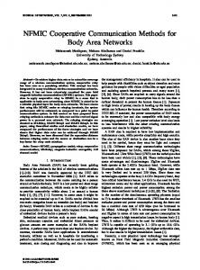
Relays in self-backhauling relaying (or type-I relays) are decode-and-forward relays, which receive and forward IP packets in the network layer, where physical layer cooperation among relays and other nodes are not allowed. In this case, a relay has its own scheduler and HARQ control, and mobile terminals may perceive a relay as another base station. On one hand, this type-I relaying design greatly reduces burden of system design at least at the mobile terminal side, since mobile terminal does not need to distinguish a relay and a base station. Hence, it is possible to deploy relays in an existing wireless network without changing existing mobile terminals’ behavior. On the other hand, as both the access link and the macro-access link can be activated in the same time-frequency resources without coordination, a relay’s signal may interfere with a base station’s signal received at a mobile terminal. In this case, similar considerations as needed for cell planning should be taken for deploying this type of relays for managing interference between relays and base stations. If no
d1 −γ P1 d2 −γ P1 and SINR2 = . (1) N N With the introduction of the relay, we suppose that the base station transmits signals to mobile terminal 1 and the relay serves mobile terminal 2 in the same frequency band. In typeI relaying, the relay and the base station do not cooperate in the physical layer, and hence the relay’s signal and the base station’s signal interfere with each other at each mobile station. Then, the SINRs with the relay are, SINR1 =
d1 −γ P1 (d2 − d3 )−γ P2 � and SINR = . 2 N + (d3 − d1 )−γ P2 N + d−γ 2 P1 (2) The network throughput values η1 and η2 in terms of bits/sec with and without the relay are, respectively, SINR�1 =
η1 = log2 (1 + SINR1 ) + log2 (1 + SINR2 ) η2 = α(log2 (1 +
5611
SINR�1 )
+ log2 (1 +
SINR�2 )),
(3) (4)
As a type-I relay is known as a base station at some mobile terminals, the type-I relay has to transmit first a few symbols in every subframe for control signaling and pilot signaling via an access link, to ensure backward compatibility to LTE. When control regions of a base station and a relay overlap in subframes, the relay is not able to receive control signaling from the base station due to being half-duplex. Hence, a new control signaling channels and methods backhaul link should be defined for the type-I relaying in backhaul links. On the other hand, in a subframe where a relay receives data from a base station in a backhaul link, the relay has to switch from transmitting mode for an access link for control signaling for its mobile terminals, to receiving mode for a backhaul link. This mode switching usually requires a time delay, this latency should be considered at a base station for designing subframes intended for transmitting data to relay in a backhaul link.
A. Joint Processing
B. Transparent Relaying for HARQ retransmissions
where Xi is the signal transmitted at Ci, Wi is the precoding matrix at Ci, and Z1 is the additive white Gaussian noise at the receiver. If each cell is serving to his/her own mobile terminals, the signals will interference with each other, then the SINR for M1 can be expressed as
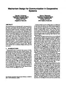
As another attempt to extend coverage of LTE-A systems while minimizing impacts on the system design and overhead, a transparent relaying scheme for HARQ retransmissions (also known as type-II relaying) has been introduced. In type-II relaying, relays are activated only for HARQ retransmissions for mobile terminals. For example, a relay listens to downlink transmissions from a base station and uplink ACK/NACK messages from mobile terminals. When the relay decodes a NACK message from a mobile terminal which has decoded the associated packet to the NACK message, it can jointly transmit retransmission signals intended for the mobile terminal together with the base station. 1) Performance Analysis: For analysis of the type-II relaying, we consider a three-node network composed of a base station, a type-II relay and a mobile terminal. We assume that the first round error probability of a packet transmitted by the base station at the mobile terminal is p1 , and the second round probability at the mobile terminal when the relay does not help is p2 . Furthermore, we assume that the second round error probability at the mobile terminal when the relay helps is p�2 . The throughput values η and η � in terms of packets per time slot, with and without the type-II relay can be calculated as, η = (1 − p1 ) + p1 (1 − p2 )/2 = 1 − 0.5p1 − 0.5p1 p2 , η � = (1 − p1 ) + p1 (1 − p�2 )/2 = 1 − 0.5p1 − 0.5p1 p�2 .
(5) (6)
Hence, deploying a type-II relay will have throughput gain if p�2 < p2 . There are multiple ways of realizing p�2 < p2 . In one example, only the relay transmits packet in the second round, as the the access link is assumed to have a better channel than the macro-access link. In another example, both the relay and the base station transmits the same signals, so that the mobile terminal receiver can get benefits from increased receive power. III. C OORDINATED M ULTI - POINT T RANSMISSIONS In this section, two important classes of CoMP transmission schemes are introduced and discussed.
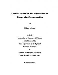
In the class of joint processing/transmission, multiple base stations (or transmission points or cells) jointly transmit signals to a single mobile terminal improve the received signal quality or actively cancel interference for other mobile terminals, or both. In this case, data intended for a particular mobile terminal is shared among different cells (cell 1 and cell 2) and is jointly processed at these cells. As a result of this joint processing, received signals at the intended mobile terminal will be coherently or non-coherently added up together. We assume that mobile user 1 (M1) is receiving signals from the three cells: Cell 1, Cell 2, and Cell 3 (denoted as C1, C2 and C3). Assume Hi1 is the channel gain from Ci to M1, the received signal Y1 at M1 can be expressed as Y1 = H11 W1 X1 + H21 W2 X2 + H31 W3 X3 + Z1 ,
SINR1 =
||H11 W1 ||2 P1 + ||H31 W3 ||2 P3 + N
||H21 W2 ||2 P2
where Pi is the transmitted power of Xi at Ci, and N is the noise power. Consider a CoMP joint processing system where C1, C2 and C3 form a CoMP cluster, M1 is then being simultaneously served by all the three cells belonging to the CoMP cluster. Under this assumption, we have X1 = X2 = X3 = X. Accordingly, the received signal at M1 can be expressed as Y1 = H11 W1 X + H21 W2 X + H31 W3 X + Z1 , Therefore, the SINR of M1 can be computed as √ √ √ ||H11 W1 P1 + H21 W2 P2 + H31 W3 P3 ||2 � . SINR1 = N It is clear that SINR1 is always upper-bounded by SINR�1 , and CoMP joint processing will always bring a SINR gain compared to single-cell operation. However, this gain is not free. Note that SINR1 is obtained under the assumption that each cell is serving his/her own mobile user while SINR�1 is obtained under the assumption that three cells are serving one mobile user. Therefore, mobile terminals under CoMP joint processing are occupying more system resources than the single-cell mobile terminals. This is actually one of the biggest hidden costs of CoMP joint processing. Taking this hidden cost in to account, assuming symmetric channel conditions, the total throughputs of single-cell operation and CoMP joint processing are � � 3 log2 (1 + SINR1 ) and log2 1 + SINR�1 respectively. Therefore, it does not worth to perform CoMP joint processing for cell-center mobile terminals where the value of SINR1 is high. Under this situation, the cost of system resource is high while SINR improvement is marginal.
5612
The above analysis is based on the fact only one mobile user is served by the CoMP cluster which is called CoMP singleuser (SU) MIMO mode. A more involved operation mode is the CoMP multi-user (MU) MIMO mode where multiple mobile terminals are joint served by the CoMP cluster. B. Coordinated Beamforming/Scheduling In the class of coordinated scheduling and/or beam-forming, data to mobile terminal is instantaneously transmitted from one of the transmission points (cells) while the scheduling decisions are coordinated to control the interference generated in a set of coordinated cells. In other words, the data intended for a particular mobile terminal, say M1, is transmitted only by C1; however, C2 will choose to serve its mobile terminals in such a way that it will create little interference to M1. This technology is also known as “interference mitigation” in the signal processing society and some methods to mitigate interference through different signal spaces can be found [11], [12]. Assume two mobile terminals, M1 and M2, are close to each other and are served by C1 and C2 respectively. The received signals, Y1 and Y2 , of M1 and M2 can be written as Y1
= H11 W1 X1 + H21 W2 X2 + Z1
Y2
= H12 W1 X1 + H22 W2 X2 + Z2 .
Accordingly, the received SINR for M1 and M2 can be expressed as SINR1
=
SINR2
=
||H11 W1 ||2 P1 ||H21 W2 ||2 P2 + N ||H22 W2 ||2 P2 . ||H12 W1 ||2 P1 + N
In single-cell operation, the precoding vector Wi of MS i is chose such that the received signal strength from the serving cell are maximized: ||H11 W1 ||2 P1 W1� = arg maxW1 ||H21 W2 ||2 P2 + N ||H22 W2 ||2 P2 . W2� = arg maxW2 ||H12 W1 ||2 P1 + N When M1 and M2 are close, it is likely that both the pairs {H11 , H12 } and {H21 , H22 } are correlated. Therefore, W1� applied in C1 is actually causing a large inter-cell interference to the received signal of M2 and vice versa. In coordinated beamforming/scheduling, the precoding vectors are joint optimized such that the SINRs at the mobile terminals are improved. That is, the CoMP cluster joint choose the precoding vectors and scheduling decisions taking into account the inter-cell interference. C. Joint Processing vs. Coordinated Beamforming/Scheduling
Differently from relaying technology, this data exchange can be done in wired backhaul; however, this still cause additional latency and impose stringent requirements for backhaul technologies. On the other hand, in coordinated beamforming/scheduling, unlike joint processing, data for an intended mobile user is only transmitted from its serving cell. This way, only channel state information and scheduling decisions are needed to be exchanged among the cells. This reduces the system complexity and backhaul traffic. Furthermore, joint processing is more sensitive to the channel feedback errors as opposed to the coordinated beamforming/scheduling, and it is difficult to ensure that the signals from different cells are constructively add at the receiver. Due to these reasons, current 3GPP community focuses more on the CoMP coordinated beamforming/scheduling for LTE-A systems. However, joint processing can be still promising if some of the practical issues can be resolved. IV. C ONCLUSION In this paper, cooperative communication technologies being considered in LTE-A have been introduced. As solutions for coverage limitation and inter-cell interference, relaying and coordinated multi-point (CoMP) transmission have respectively been discussed, and their performances and design challenges have been investigated. R EFERENCES [1] 3GPP TR 36814, Evolved Universal Terrestrial Radio Access (E-UTRA); Further advancements for E-UTRA Physical layer aspects Physical channels and modulation, ver 1.0.0, Feb. 2009. [2] 3GPP TS 36211, Evolved Universal Terrestrial Radio Access (E-UTRA); Physical channels and modulation, ver 8.7.0, Jun. 2009. [3] T. M. Cover and J. A Thomas, Elements of Information Theory, Wiley, 1991. [4] D. Tse and P. Viswanath, Fundamentals of Wireless Communications, Cambridge University Press, 2005. [5] H. Zhang, N. B. Mehta, A. F. Molisch, J. Zhang, and H. Dai, “Asynchronous Interference Mitigation in Cooperative Base Station Systems,” IEEE Tr. Wireless Comm., Vol. 7, Issue 1, pp. 155-165, January 2008. [6] P. Gupta and P. R. Kumar, “The Capacity of Wireless Networks,” IEEE Trans. Inform. Theory, Vol. 46, No. 3, pp. 388–404, Mar. 2000. [7] A. Sendonaris, E. Erkip and B. Aazhang, “User Cooperation Diversity -Part I: System Description,” IEEE Trans. Comm., Vol. 51, No. 11, Nov. 2003. [8] Y. H. Nam, K. Azarian, H. El Gamal and P. Schniter “Cooperation through ARQ,” Sig. Proc. Adv. Wireless Comm. (SPAWC), Jun. 2005. [9] J. N. Laneman, D. N. C. Tse and G. W. Wornell, “Cooperative Diversity in Wireless Networks: Efficient Protocols and Outage Behavior,” IEEE Trans. Inform. Theory, vol. 50, no. 12, pp. 3062-3080, Dec. 2004. [10] K. Azarian, H. El Gamal and P. Schniter, “On the Achievable DiversityMultiplexing Tradeoff in Half-Duplex Cooperative Channels,” IEEE Trans. Inform. Theory, vol. 51, no. 12, pp. 4152-4172, Dec. 2005. [11] J. Kotecha and J. Mundarath, “Non-Collaborative Zero-Forcing Beamforming in the Presence of Co-Channel Interference and Spatially Correlated Channels,” in Proc. of IEEE VTC, pp. 591-595, Fall 2007. [12] L. Liu, J. Zhang, J. Yu and J. Lee, “Inter-Cell Interference Coordination Through Limited Feedback,” Special Issue on Multicell Cooperation and MIMO Technologies for Broadcasting and Broadband Communications, International Journal of Digital Multimedia Broadcasting, 2009.
It is expected that CoMP joint processing will bring more significant system improvement at a higher implementation cost. For example, in CoMP joint processing, the data together with channel related information for different mobile users needs to be exchanged among the cells within CoMP cluster.
5613