two stems in the same plane. 1ACCEL Company, Bergisch Gladbach, Germany. Proceedings of 2005 Particle Accelerator Conference, Knoxville, Tennessee.
Proceedings of 2005 Particle Accelerator Conference, Knoxville, Tennessee
COUPLING METHODS FOR SUPERCONDUCTING CH-CAVITIES ∗ H. Liebermann, H. Podlech, U. Ratzinger, A. Sauer, Institut f¨ur Angewandte Physik, Frankfurt, Germany Abstract The cross-bar H-type (CH) cavity is a multi-gap drift tube structure based on the H-210 mode currently under development at IAP Frankfurt [1]. Based on detailed numerical simulations a 19 cell prototype cavity from massive Niobium was realized. Experimental investigations have started already. With respect to rf coupling inductive coupling was applied successfully for cavity rf conditioning at room temperature with power levels up to 2 kW. Capacitive coupling through the girder is however preferred in case of sc operation. Recent investigations led to a modified cavity geometry which allows to integrate a capacitive power coupler with Qe values down to 106 in future CH-cavities. Main consequences on the cavity are significantly lower and broader girder profiles as well as simplified stem geometries (round instead of elliptical stem bases). These modifications will provide space for power couplers through the girders. Additionally, the cavity stiffness against vacuum forces is improved by these modifications.
To demonstrate the capabilites of the CH-DTL, it is foreseen to test an sc CH cavity prototype. A design and engineering study has been performed in close cooperation with industry1 . This study showed the feasibility of the production of superconducting CH cavities. The cavity production started in 2003; the completed cavity was delivered in April 2005 [2]. frequency [MHz] beta Ra /Q [kΩ] Epeak /Ea Bpeak /Ea [mT/MV/m] cavity length [m] gaps aperture diameter [mm] tank diameter [m] stem width a [mm] stem width b [mm]
352 0.1 3.18 6.16/4.87 7.94/6.27 1.048 19 25 0.28 12.5 20
Table 1: Parameters of the prototype cavity (full/active length) (a and b see fig. 6)
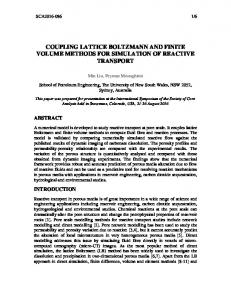
SUPERCONDUCTING (SC) CH-PROTOTYPE In sc cavities there is no cooling problem as in cw operated rt (room temperatur) linacs. In general, sc linacs can be operated at higher gradients above a certain duty factor.
COUPLER DEVELOPMENT FOR THE PROTOTYPE For coupling into superconducting structures the external Q-value must cover the range from 106 to 109 . Different kinds of couplers were examined with MicroWave Studio [3] and measured at a copper model[4].
Figure 1: The sc 352 MHZ CH prototype On the other hand, at low duty factors and high beam currents rt structures are very favourable because they are less expensive and can tolerate dark current contributions. ∗ Supported
Figure 2: Capacitive coupling through one girder between two stems in the same plane 1 ACCEL
by GSI Darmstadt, EU and by BMBF, contr. no. 06F134I
c 0-7803-8859-3/05/$20.00 2005 IEEE
922
Company, Bergisch Gladbach, Germany
Proceedings of 2005 Particle Accelerator Conference, Knoxville, Tennessee Finally a capacitive coupling (fig.2) through the girder of the CH-structure was chosen and studied in more detail. The inner conductor of the coaxial line is facing a drift tube with opposite polarity. It turned out that by this method external Q-values from 104 to 1011 can be achieved (fig.3). In order to verify the calculations with MicroWave Studio, measurements on the copper model were performed. These show a good agreement with the calculations. After getting confidence in the simulations from the Figure 5: Coaxial coupler for the first cold tests.
OPTIMIZATION FOR CAPACITIVE COUPLING In order to operate future CH-cavities with more power, calculations were accomplished for the optimization of the girders and stems with MicroWave Studio.
Figure 3: Calculations and measurements on capacitive couplers for the copper-model (Fig.2) of the CH-Cavity. 0mm corresponds to the girder surface plane. comparison with model measurements, calculations for the superconducting prototype of the CH structure were performed. The results of the calculations are represented in figure 4. It showed that with a coupler position between -10 and +10 mm external Q-values between 105 and 109 can be achieved (fig.4). Figure 5 shows the coaxial coupler for the first cold tests of the sc CH-Cavity.
Figure 4: Calculations on capacitive couplers for the s.c. prototype of the CH-Cavity.
Figure 6: Stem of an sc CH-Cavity. In the first step the girder geometry was changed to achieve a higher stability in relation to the vacuum forces. It became clear that the old stem form has some disadvantages for a girder variation, since it would lead to strong field increases (fig.7).
Figure 7: Electric and magnetic peak fields in dependence of the girder height Geometry of the stems was changed to minimize the
923
c 0-7803-8859-3/05/$20.00 2005 IEEE
Proceedings of 2005 Particle Accelerator Conference, Knoxville, Tennessee peak fields. In addition, the stem width in both directions a and b was varied. A widening of the stems led to a reduction of the fields (fig.8).
larger coupler. With the new girder and stem it is possible to get more power into the CH-cavity.
Figure 10: Qext for the optimized Cavity.
frequency [MHz] beta Ra /Q [kΩ] Epeak /Ea Bpeak /Ea [mT/MV/m] cavity length [m] gaps aperture diameter [mm] tank diameter [m] stem width a [mm] stem width b [mm]
Figure 8: Electric and magnetic peak fields in dependence of the stem width a.
CAPACITIVE COUPLING FOR THE OPTIMIZED SC CH-CAVITY After the optimization of the girder and stem geometry, we performed simulations for capacitive coupling. We use nearly the same position as for the prototype. Because of wider girders we can use a bigger coupler for high power. Figure 9 show the position of the new coaxial coupler. It can be seen that the coupler is not centered on the girder.
352 0.1 3.28 6.21/4.92 8.19/6.46 1.048 19 25 0.28 21.4 27
Table 2: Parameters of the optimized cavity for capacitive (full/active length).
REFERENCES [1] H. Podlech, Development of Superconducting and Room Temperature CH-Structures, Proceeding of the LINAC 2004, L¨ubeck, Germany [2] H. Podlech, First Tests of the Superconducting CH-Structure, these proceedings [3] http://www.cst.com [4] H. Liebermann, H. Podlech, U. Ratzinger, A. Sauer, Status of Coupler Development for the 352 MHz Superconducting CHCavity, Proceeding of the LINAC 2004, L¨ubeck, Germany
Figure 9: Optimized sc CH-Cavity for capacitive coupler Figure 10 shows that with the new coupler it can be reach external Q-values between 106 and 108 . So it is possible to use it for the sc CH-Cavity. Table 2 shows that every parameter is nearly the same as for the prototype, but the new girder and stem geometry give the cavity more stiffness and there is more space for a
c 0-7803-8859-3/05/$20.00 2005 IEEE
924