Crafting a software process improvement approach—a retrospective systematization Marco Kuhrmann University of Southern Denmark, Mærsk Mc-‐Kinney Møller Institute, Campusvej 55, DK-‐5230 Odense M, Denmark and Technische Universität München, Faculty of Informatics – Software & Systems Engineering, Boltzmannstr. 3 85748 Garching, Germany
Corresponding Contact: E-‐Mail:
[email protected] Phone: +45 24 60 14 22
© Wiley 2015. Preprint. This is the author's version of the work. The definite version was accepted in Journal of Software: Evolution and Process, Issue assignment pending, The final version is available at http://onlinelibrary.wiley.com/doi/10.1002/smr.1703/abstract
JOURNAL OF SOFTWARE: EVOLUTION AND PROCESS J. Softw. Evol. and Proc. 0000; 00:1–33 Published online in Wiley InterScience (www.interscience.wiley.com). DOI: 10.1002/smr
Crafting a Software Process Improvement Approach – A Retrospective Systematization Marco Kuhrmann12∗ 1 University 2 Technische
of Southern Denmark, Mærsk Mc-Kinney Møller Institute, Odense, Denmark Universit¨at M¨unchen, Faculty of Informatics, Software & Systems Engineering, Garching, Germany
SUMMARY Structured approaches are beneficial for successful software process improvement (SPI). However, process engineers often struggle with standardized SPI methods, such as CMMI or ISO 15504, and complain about too generic or voluminous approaches, or methods that are alien to the organizations in which SPI is conducted. Therefore, process engineers need to customize existing SPI models or develop new approaches for company-specific SPI programs. While conducting SPI in the context of the German V-Modell XT, we faced the need to develop a new method for artifact-based SPI. In the process, we found that the construction procedures of SPI models are barely documented and, thus, their successful adaptation solely depends on the process engineers’ expertise. With this article, we aim to address this lack of support and provide a structured reflection on our experiences from creating and adopting the Artifact-based Software Process Improvement & Management (ArSPI) model. We present the steps of the construction procedure, the validation and the dissemination of the model. Furthermore, we detail on the applied methods, the design decisions, and the challenges encountered. By providing a reference procedure and tested methods, we support process c 0000 John Wiley & Sons, Ltd. engineers with the creation and adoption of SPI approaches. Copyright Received . . .
KEY WORDS: Software Process Improvement; SPI; Methodology; Construction Procedure; Experience Report; Artifact-orientation; V-Modell XT
1. INTRODUCTION Software process improvement (SPI) is important for all organizations (regardless of their size) to improve the quality of a software product or speed of development, and to succeed in the market [14, 45]. However, improving software processes is a challenging task, as many different stakeholders, project settings, and contexts and goals need to be considered. The key player, who has to pay attention to all these factors, has to weight and integrate them into a sound improvement concept and, finally, develops or improves a process is the process engineer [45]. To set up and conduct SPI, process engineers look for SPI models that contain, e.g., reference models, best practices, evaluation material, or concrete guidance, for this task. However, process engineers often struggle with standard SPI models such as CMMI [8] or ISO 15504 [16]—too generic, inappropriate for the actual process or context, or focused on assessments rather than on improving a process, as for instance discussed in [10, 5, 21] or [51]. In response, several light-weight SPI approaches were developed over the years, such as PROCESSUS [14], BG-SPI [3], COMPETISOFT [44], BOOTSTRAP [35], or standards such as ISO 29110 [18] (a tailored variant of ISO 12207 [17]) that ∗ Correspondence to: University of Southern Denmark, Mærsk Mc-Kinney Møller Institute, Campusvej 55, 5230, Odense,
Denmark. E-Mail:
[email protected] c 0000 John Wiley & Sons, Ltd. Copyright Prepared using smrauth.cls [Version: 2012/07/12 v2.10]
2
M. KUHRMANN
also address small-scale SPI, e.g., in smaller companies. In summary, a variety of SPI models is available competing for the process engineers’ favor. However, the question how process engineers create or customize an SPI method if none of the available methods fits into the actual context remains unanswered. For instance, given a setting in which a company aims to establish an SPI program based on CMMI, process engineers face the challenge that CMMI has not been designed with the purpose to guide organizations through the implementation of particular improvements. Thus, process engineers first have to create a companyspecific SPI approach containing that appropriate guidance, e.g., by combining several other SPI models. In Germany, we faced another challenge: software processes can rely on artifact-based design approaches as well as on activity-based ones. Aforementioned SPI approaches that focus on the optimization of workflows (activity-based approach) can scarcely be applied to artifact-based process models. Instead, process engineers need an approach focussing on the improvement of the process artifacts rather than on the methods used to create these artifacts. Therefore, process engineers often develop a portfolio of methods and artifacts themselves—usually in a pragmatic manner and under pressure, as this is not part of an SPI project itself. As a consequence, artifacts documenting an SPI project and its outcomes are oftentimes only partially created, remain incomplete, inconsistent, or decisions made in the project are not verifiably and transparently documented. This endangers the success of the whole SPI program, as for instance designs become inconsistent with an evolving process. During the development and improvement of the German V-Modell XT (reference process and its variants† [28]), we experienced the need for an new SPI method. At this time, the V-Modell XT already contained an SPI method, which we, however, could not use for several reasons (cf. Section 4.3.2). The major arguments against reusing and adopting other standard SPI models were: • The V-Modell XT is a process framework that allows for developing whole software process lines (SPL; [49, 38]) and, thus, an SPI method must explicitly support the corresponding improvement and management procedures (e.g., in the context of evolving processes). Since the framework also allows for stand-alone processes that are not part of a process line, the SPI method must also be scalable covering small SPI projects aiming at stand-alone processes as well as large-scale SPL-based SPI programs. • The V-Modell XT is an artifact-based process framework comprising metamodels, tool infrastructures, and so forth [27]. Therefore, an SPI method for the V-Modell XT must explicitly focus the improvement of artifact models‡ . Furthermore, the SPI method has to guide the process engineer through the improvement procedures specific to the framework, e.g., guiding the tool-based authoring, or integration and deployment procedures. • The V-Modell XT is used to model project-like endeavors, rather than continuous processes. Therefore, an SPI method for the V-Modell XT must bridge the gap between company-wide continuous improvement programs and single SPI projects. To this end, the SPI method needs to define an SPI project (aiming at improving a particular software process [15]) and its integration into a company-wide software process management (comprising all activities and infrastructures required to support SPI [21]).
As we had no appropriate method at our disposal, we had to develop the SPI approach ourselves. Moreover, due to the special set up of the SPI activities (Section 4.1), we had to start developing the SPI approach beside running SPI projects, which made it hard (and partially impossible) to establish a set of research activities to craft the intended SPI approach. † Terminology:
In the context of a software process line [49, 38], a reference process is the basis to derive further process variants. Similar to software product lines [4, 20], the reference process defines basic process assets as commonalities that are mandatory for all derived variants, which can modify and/or extend the reference process. In the V-Modell XT process line, a tree is used to structure software processes: a process variant can, again, serve as reference process for further variants (cf. [23] for the V-Modell XT family tree). ‡ Terminology: An artifact model contains a set of artifacts and defines the dependencies between the comprised artifacts, whereas an artifact is according to [11] any (tentative) deliverable that is created, consumed, or modified by an activity, that defines a structure, and is embedded into a dependency model. c 0000 John Wiley & Sons, Ltd. Copyright Prepared using smrauth.cls
J. Softw. Evol. and Proc. (0000) DOI: 10.1002/smr
CRAFTING A SOFTWARE PROCESS IMPROVEMENT APPROACH
3
Problem Statement Although there exists a plethora of evaluated SPI approaches, little is yet contributed in literature about how to create, customize, and/or improve an SPI method if available approaches do not meet the actual context. In the context of the German V-Modell XT, we had no appropriate SPI model at our disposal and, thus, had to define a new SPI model ourselves. In the process, we witnessed a missing guidance for the construction of SPI models. Creating and implementing a systematic construction procedure is challenging: Since only few and scarcely repeatable guidelines are available, process engineers in practice are forced to develop their own portfolio of methods “on the fly” by means of “trial and error” approaches. This means that they risk missing the target by focusing on the SPI model instead of the processes to be improved. Objectives To support process engineers, we aim at systematizing our experiences made during the development of the Artifact-based Software Process Improvement & Management (ArSPI) model. Therefore, we collect activities and artifacts, structure the knowledge, and document all steps of the construction procedure. The construction procedure emerges from pragmatically as well as systematically conducted SPI projects, student labs, and external validation. We aim to distill a procedure for the creation and optimization of SPI methods to lay the foundation for further empirical research on the efficiency and the improvement of SPI methods. Contribution In this article, we contribute our systematized experiences in crafting an SPI method condensed into a concrete construction procedure, which emerges from more than 8 years of experiences in SPI in different organizations in Germany and Eastern Europe, teaching SPI in academia and practice, and evidence-based research. We contribute a detailed description of how ArSPI was developed and validated, which (empirical) methods were applied in the particular steps, and which problems occurred during the development, and distill a set of methods that showed beneficial. With our contribution, we fill a gap in literature by documenting and systematizing the construction procedure of an SPI model. We aim to support practitioners as well as researchers. Researchers can directly build their teaching and research activities on our work, e.g., by replicating the studies conducted in the construction, or by using the presented construction procedure as a starting point for further research. Practitioners can benefit from our experiences by using methods that we applied and using/adopting the outcomes created during the development of ArSPI if they need to create or customize an SPI method themselves, e.g., by adopting the construction procedure, using artifacts, or by implementing methods from the pool of methods that we applied. We explicitly do not aim at replacing any established SPI approach nor do we want to evaluate, compare, or rate certain SPI approaches. With our report we aim to contribute to a barely reported topic in literature by describing how we crafted our SPI method—our approach, experiences, and difficulties. Outline The remainder of this article is organized as follows: In Section 2, we discuss the related work. In Section 3, we present the ArSPI model from a high-level perspective to set the context before describing the model’s creation in Section 4. We describe the overall crafting process as well as single steps, analysis procedures, design decisions, and resulting model parts. Finally, we distill a reusable construction procedure and share our experiences and the lessons learnt before concluding the article in Section 5.
2. RELATED WORK Investigating the literature on SPI, many contributions can be found proposing and discussing SPI models. On the one hand, we find contributions in the context of standard SPI and life cycle models such as CMMI [8], ISO 15504 [16], and ISO 12207 [17]. On the other hand, a lot of approaches aiming at smaller SPI endeavors are available, e.g., COMPETISOFT [44], PROCESSUS [14], BGSPI [3], BOOTSTRAP [35], ImprovAbility [7], or ISO 29110 [18]. These contributions focus on proposing the models, on evaluating their application, or on simplifying assessment procedures. c 0000 John Wiley & Sons, Ltd. Copyright Prepared using smrauth.cls
J. Softw. Evol. and Proc. (0000) DOI: 10.1002/smr
4
M. KUHRMANN
However, with this article, we want to report on the creation of an SPI model—not on its application. Investigating the aforementioned contributions for insights regarding their respective construction procedures, we find statements such as “The PROCESSUS SPISC is derived from requirements and characteristics of the two best known models for software process improvement – the ISO model [. . . ] Guidelines and the SEI SW-CMM [. . . ]” [14], or “We have developed BG-SPI [. . . ]” [3]. For [14], it was mentioned that the approaches were compared while detailed information regarding the construction procedure was not provided. Moreover, Ahlemann and Gastl [1] state that the construction process is usually not documented at all in reference modeling techniques, which also holds for SPI approaches being reference models for conducting SPI. Insights into the development of an improvement method are scarcely reported. For instance, Raninen et al. [47] present the LAPPI approach and briefly describe its development, as the construction procedure is not the main contribution of the article. The construction procedure is based on the constructive research approach [43]; the evolution of the method was complemented by workshops. The evolution of LAPPI comprised five phases in which the approach was stepwise developed instrumenting industry case studies. Other instruments, such as controlled environments (labs), were not mentioned. Laporte and O’Connor give insights into the development of the ISO 29100 standard in [36, 41, 37]. They describe a procedure, which was adapted from the innovation-development process model [48]. In this procedure, different instruments, e.g., expert interviews and survey-based research, were applied. Notably, in their description of the fifth step of the utilized model, they advocate for conducting industry-hosted validation in order to disseminate the standard, reduce risk, and foster learning about issues. The basic characteristics are similar to the approach we present in this article, but differ in details, e.g., academic validation based on controlled experiments was not mentioned in [37]. O’Leary and Richardson [42] describe a procedure in which a multi-method research approach [55, 1] was used to develop a process reference model. They describe the overall approach and provide insights into the different stages. To this end, the contribution is similar to the report that we provide. The major difference is that O’Leary and Richardson followed a planned approach while we needed to develop the procedure “under way” (Section 4.2). Furthermore, regarding the academic analyses, we added lab-based experiments to the method portfolio, which were not mentioned in [42]. However, they explicitly name the problem that reference models usually do not provide a detailed description of the construction process, which supports our findings from investigating the literature. Although O’Leary and Richardson aim at a different goal, the domain is similar and we consider an SPI model to be a reference model too, and we thus also compare our experiences to their contribution (Section 5). A mixture of (research) methods was also instrumented by Christiansen and Johansen to craft the ImprovAbility model [7]. Among others, project observation and literature studies were utilized to distill a model in which, based on 20 parameters, the readiness of a company is determined, and appropriate improvement opportunities are derived. In the context of our work, M¨unch et al. [21] contribute the 8-stepapproach to develop descriptive process models, and they also name several empirical methods, e.g., controlled experiments and surveys, to determine effects of improved processes. The 8-stepapproach describes the basic steps to define goals, select modeling notations, gather data, create designs, etc. The overall presentation of the approach is done by example using industry case studies. The 8-step-approach is an activity-based guideline to construct process models—design artifacts are partially mentioned, but not defined. Furthermore, also for the 8-step-approach, a construction procedure is not presented in [21]. The article at hand thus fills a gap in literature by (1) providing detailed information on constructing an artifact-based SPI model using ArSPI (Section 3) as case, (2) by giving an example how we integrated empirical methods into the construction procedure and how the outcomes affected following activities, and (3) by distilling a generalized construction procedure and its critical discussion.
3. AN ARTIFACT-BASED SOFTWARE PROCESS IMPROVEMENT APPROACH Before describing the construction procedure, we briefly introduce the resulting ArSPI model to set the context. In this section, we only provide a high-level perspective, as we provide more details c 0000 John Wiley & Sons, Ltd. Copyright Prepared using smrauth.cls
J. Softw. Evol. and Proc. (0000) DOI: 10.1002/smr
5
CRAFTING A SOFTWARE PROCESS IMPROVEMENT APPROACH
Software Process Management (SPM)
Software Project
Project and Quality Management
Legend: K
SPI Key Artifact S
Support Artifact
Configuration, Change, and Release Management Life Cycle Phase with Quality Gate
Software Process Improvement (SPI) - Processes
Discipline or Activity
Software Process Improvement (SPI) - Artifacts Analysis
Conceptualization
Realization
Deployment
K
Process Requirements
K
Conceptual Process Design
K
Technical Process Design
K
Process Release
K Life Cycle Phases
Vision S S
Measurement Plan Training Plan
S
…
Process Life Cycle Support Support Artifacts
SPI Key Artifacts
Project- and Quality Management
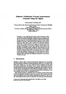
Figure 1. Overview of the ArSPI model.
during the description of the particular crafting activities. As it is not the primary purpose to present ArSPI in every detail, all designs, guidance, and templates regarding ArSPI§ are available from our complementing technical report [23] and the ArSPI website. Figure 1 shows the “bird’s eyes perspective” of the ArSPI model, which contains three major areas: software process management (SPM), software process improvement (SPI), and software projects. According to M¨unch et al. [21], software process management comprises all activities and infrastructures required to support SPI. Especially, this includes the management of the company-wide deployed reference processes. According to Humphrey [15], SPI projects aim at improving a particular software process (that can be part of a software process line). Finally, software projects are the process consumers that instantiate and implement a (managed) software process. Software projects can also include “local” SPI activities, e.g., the improvement of one particular process in a project. The ArSPI model provides a unified view on SPI and SPM. Because of the V-Modell-XTbased setting (Section 4.2) and as recommended by Frailey [12], we implemented ArSPI using artifact-based design approaches [11] and, thus, put an emphasis on artifacts. ArSPI defines a set of 5 key artifacts and 24 management- and supporting top-level artifacts complemented with respective activities. The key artifacts of ArSPI are the process requirements, conceptual process design, technical process design, process release, and the process life cycle support documentation (Section 4.3.3) that are embedded in a simple four-phased life cycle model [26], which is based on the PDCA cycle [9]. These artifacts provide the basic structure to capture the process requirements, and to document the process designs and the processes required for an adequate process life cycle support, e.g., training and deployment plans, or measurement plans, supporting an organizationwide SPM.
§ ArSPI
is the new and generalized artifact-based SPI method emerging from conducting SPI in the context of the VModell XT. The method is based on a complex artifact model designed in UML. All detailed designs, such as artifacts, dependencies, tailoring profiles, and so forth can be depicted from our complementing technical report [23]. Furthermore, an initial implementation of ArSPI using the Eclipse Process Framework is available. The technical report and the latest versions of the ArSPI-EPF implementation can be found at: http://www4.in.tum.de/˜kuhrmann. c 0000 John Wiley & Sons, Ltd. Copyright Prepared using smrauth.cls
J. Softw. Evol. and Proc. (0000) DOI: 10.1002/smr
6
M. KUHRMANN
Although emphasizing the artifacts, ArSPI also comprehends a rudimentary process model that defines the necessary basic processes to create and link the ArSPI artifacts (cf. Section 4.3.7). Furthermore, ArSPI also describes a life cycle model in which SPI projects are integrated with the performing company’s processes, e.g., release-, configuration-, and change management. The model defines, inter alia, which artifacts are inputs for organization processes (releases, training concepts, training plans, etc.), or which artifacts the organization is expected to deliver to support SPI projects (vision or change/feature requests, etc.).
4. CRAFTING THE ARSPI APPROACH We describe the crafting approach in detail by first giving an overview of the entire approach in Section 4.1 and the context in Section 4.2 before describing the steps in detail (Sections 4.3-4.5). For each step, we refer to the previously introduced ArSPI model and show which parts result from which analysis results and design decisions. We conclude this section by discussing and integrating our approach into a reusable template (Section 4.6), and with a summary of our lessons learnt. 4.1. Overview of the Crafting Approach Over the years, we were involved in a number SPI projects and SPI-related tool development projects for different clients in industry as well as in the context of government agencies¶ in which we could gather manifold experiences. WiBe, SPW 2005
2005
2010
Project P1
Project P2 – Development
Project P4
Project P5
Project P3
Witt-Weiden, SPIP 2008 Study, EuroSPI 2011
Step 1: Knowledge Extraction and Conceptualization Repository analysis
Pilot Project Analysis, iX 2005
State-of-theart analysis
Document analysis
Initial (pre-)ArSPI approach (early draft), 2011
Several technical reports on project outcomes and concepts
V-Modell XT customization approach, Springer 2011
Further material, e.g. CMMI, ISO 15504 Step 2: Internal Validation and Consolidation
2012
Expert Interviews
Project P2 – Maintenance
Student Lab
Lab/Experiment, PROFES 2013 Teaching concept, ICSE 2013
Project P6
Consolidated ArSPI model and complementing material, TUM 2013
2013
Further research
Step 3: Dissemination Project P7
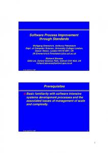
Figure 2. Overview of the construction procedure, SPI projects, and main contributions.
¶ The
referred projects were operated in cooperation with partners from Germany and Eastern Europe; namely: the Federal Ministry of the Interior, the Federal Network Agency, the Federal Office for Administration, the Centre for Information Processing and Technology, the Federal Ministry of Defense, Witt-Weiden (Otto Group), and the Bulgarian Council of Ministers. For confidentiality reasons, we are not allowed to name all the projects and are also not permitted to always provide exact numbers. To this end, we use intervals instead of exact numbers, and describe the context of the projects generically. c 0000 John Wiley & Sons, Ltd. Copyright Prepared using smrauth.cls
J. Softw. Evol. and Proc. (0000) DOI: 10.1002/smr
CRAFTING A SOFTWARE PROCESS IMPROVEMENT APPROACH
7
Figure 2 summarizes the steps conducted over the years developing ArSPI, and assigns the projects and activities that were performed in the respective phases. The subsequently presented construction procedure was conducted in three steps: knowledge extraction and conceptualization (step 1), internal validation and consolidation (step 2), and dissemination into practice (step 3). Figure 2 shows the construction procedure as it was systematized in retrospective. Background and context (Section 4.2 and Appendix A) were set by a number of pragmatically conducted SPI projects that generated the SPI-related knowledge used to craft the ArSPI approach. Just with the beginning of the conceptualization (step 1), we stepwise moved to a planned approach that resulted in the partially planned step 2 and the fully planned step 3. SPI projects aiming at developing and/or improving software processes were then used to validate ArSPI and to explicitly conduct case studies. In the overall construction procedure, we applied different instruments to extract information from the SPI projects, and to design and validate the resulting approach (or parts of it); namely: data repository analysis, document analysis, surveys and interviews, experiments, and monitoring and evaluation of projects (case study research). In subsequent sections, we describe the particular steps, the applied instruments, and the outcomes of the respective phases in detail. 4.2. Project Context & Background The process of knowledge generation is specific to the actual domain and the context of conducted SPI projects (Figure 2) and, thus, hard to repeat. In this section, we provide some insights into the knowledge generation process to set the context and to give some insights into the background of developing ArSPI. We generated the knowledge by conducting a number of SPI projects in the context of the V-Modell XT—each complemented with pilot projects or application/validation tasks. In Table V (Appendix A), we give information regarding the projects on which our work is based. The basis is project P1; the V-Modell XT reference process, which—on the one hand—is the German standard development process for IT projects (published by the Ministry of the Interior) and—on the other hand—serves as the reference process on which all variants of the V-Modell XT process line are built. In the context of the development of the reference process, more than 10 pilot projects were performed [39]. Three pilot projects (until 2008) aimed at creating companyspecific V-Modell XT variants. The corresponding activities and outcomes were reported, e.g., in [2] (Witt-Weiden) or [31] (WiBe). Due to the generic nature of the reference model, special attention was paid to its adaptation and customization. To this end, project P4 (Witt-Weiden; [2, 6]) was operated as a self-contained research project in which a generalized improvement approach should be developed. Complementing the SPI projects, we conducted a first study [30] on the dissemination and application of the V-Modell XT with the purpose of, inter alia, determining user requirements that should be included in the improvement of the reference process. At this time (2008/2009), the demand for a structured SPI approach that allows for a systematic SPI paying special attention to the demands of the development of process variants that rely on an evolving reference process became obvious [40, 50]. As the technical backbone was in place, a corresponding method needed to be developed. Also, agile methods and a sufficient tool support became more relevant to the partners so that research on integrating agile and regulated processes and on process enactment (e.g., [32]) should be integrated thus increasing the complexity of the respective SPI projects. Nevertheless, due to the SPI projects we generated project data and several design and realization artifacts that we already started to reuse ourselves, and that served as the major inputs for our research. In summary, we conducted a number of SPI projects (Figure 2) that included about 10 pilot projects and several activities regarding the development of process-supporting tools. As the original reference process was a straightforward design, several difficulties occurred over time, e.g., management effort of SPI endeavors in the context of an evolving reference model, management of process variants, sufficient support tools, and a missing systematic SPI approach. 4.3. Step 1: Knowledge Extraction and Conceptualization Facing the challenges from our SPI projects, we started to analyze our own material as well as standardized SPI-related material for the purpose to develop (1) a best-practice-based SPI approach c 0000 John Wiley & Sons, Ltd. Copyright Prepared using smrauth.cls
J. Softw. Evol. and Proc. (0000) DOI: 10.1002/smr
8
M. KUHRMANN
and (2) a practical guideline to support process engineers to implement a process using the VModell XT framework—in other words: a generic method to organize SPI in general and an instance for SPI projects using the V-Modell XT. In this section, we describe the process of knowledge extraction and the instruments used in this process, and the conceptualization of our SPI approach. 4.3.1. Applied Instruments in the Knowledge Extraction. The goal of the knowledge extraction was to analyze the past projects, to screen state-of-the-art literature, and to harvest best practices and reusable assets, e.g., documents and planning templates. Therefore, we analyzed the past SPI projects and further external material using the instruments from Table I. Applying these instruments aimed at creating an initial set of consolidated artifacts and best practices that were used in the past SPI projects. Furthermore, obvious gaps and such in relation to standard procedures should be identified. Table I. Instruments used in the knowledge extraction.
Instrument
Description
Repository Analysis
As we had access to all the repositories comprising the process models and the respective project documentation we analyzed these repositories searching for project-management-related material, and for material related to process requirements, designs, or realizations. This analysis was done by manually mining all 5 repositories, which contained the project data.
State-of-theArt Analysis
As SPI is a well-established and frequently researched topic (in terms of success factors, human aspects, etc.), we analyzed available standard material in order to find best practices and reusable assets. During this analysis, we also took the reported case/field studies (Appendix A) into consideration to reflect on our own experiences and to compare those to further reports from literature. The analysis followed a snowballing [22] approach: we initially analyzed a small set of standard literature (e.g., CMMI, ISO 15504, VModell XT), referred (scientific) reports, and stepwise extended the set of analyzed standards/approaches/literature.
Document Analysis
The majority of the mined material was in the format of documents, e.g., Word files, spreadsheets, presentation slides. For the purpose of generalization, we investigated these documents, clustered them, and compared them in order to map contents, find similarities, and—also considering the contributions of (external) standards from the state-of-the-art analysis—to identify gaps.
4.3.2. Results from the Knowledge Extraction. In the following, we present the major results from the extraction process. Results from the Repository Analysis In Appendix B, Table VIII and Table IX summarize the major outcomes of the repository analysis (categorized into artifacts and methods that the projects contributed). Here, we summarize the basic findings. In all analyzed projects, the process release was of special importance (stored as zip-files containing the releases, change history, tools supporting the build etc., or as self-contained installer). In project P1, a comprehensive build infrastructure was found. For project P2, we also found a “delivery layout”, which clearly stated, e.g., which files are required for a release, which versions of supporting tools are required in which configuration, and the steps to be performed in the packaging process. In P2, we also found explicit life cycle support documentation. Since this particular document could not be found in the other projects, we searched for the reasons and found out that the client planned to install a person, who is responsible for the process’s maintenance after the final delivery. Therefore, the client demanded an explicit artifact that documents the organization c 0000 John Wiley & Sons, Ltd. Copyright Prepared using smrauth.cls
J. Softw. Evol. and Proc. (0000) DOI: 10.1002/smr
CRAFTING A SOFTWARE PROCESS IMPROVEMENT APPROACH
9
of the process (on the technical level) and the definition of a change management and improvement process (which we also partially found in P3). Another finding of the repository analysis was the absence of explicitly managed requirements artifacts. Only projects P2 and P3 explicitly defined their process requirements; all other projects only partially managed the requirements. Therefore, methods for the requirements elicitation could only partially crafted, but methods for quality assurance could be extracted from all analyzed projects. All projects relied on (internal/external) reviews. For instance, in projects P1 and P3 external expert boards were installed to review and discuss the process in general or parts thereof. Regarding the process design, design workshops and prototyping were the preferred instruments whereas a formally documented design approach could not be found. Results from the State-of-the-Art Analysis The state-of-the-art analysis comprised different activities, e.g., the analysis of standards in the area of process and project management. Furthermore, we analyzed our own case studies and, eventually, we analyzed the V-Modell XT itself as it also claims to support SPI projects based on best practices. In the following, we focus on the question why we did not simply use the material already available from the V-Modell XT. When project P3 (Figure 2, Appendix A) was initiated, the client demands a structured and reproducible approach, and defined deliverables. To this end, we analyzed the V-Modell XT (reference process, v1.3) and found: • In order to set up and organize P3, a tailoring of the V-Modell XT was performed that resulted in a standard SPI project template. However, the template was superficial, as no concrete methods for SPI-specific project management, planning, controlling, etc. were included. • The standard template defined a work product “Improvement concept for a development process” that comprises the requirements, realization concept, and the concept for pilot projects. A ‘real’ requirements engineering approach or a ‘real’ design approach was not available. Deployment was not mentioned at all. • The standard template defined a work product “Organization-specific development process”, which comprises, e.g., the process itself, metric catalogs, training concepts, training material, etc. Again, self-contained approaches or recommendations were not available. • The standard template defined a work product “Evaluation of a development process” that addresses process assessment as well as (parts of) the process-related requirements engineering. However, this particular artifact aimed to assess a given process (comparable to CMMI) while follow-up activities (requirements engineering, design, etc.) remain undefined. • The standard template was focused on single SPI projects and did not explicitly pay attention to long-term strategies, company-wide process management, etc.
In summary, we rejected the standard template for project P3 and decided (end of 2009) to develop our own approach that basically follows the standard template, but provides more structure, precisely defined artifacts, and a meaningful dependency model that helps to identify important artifacts. In order to address the shortcomings of the standard template, we also investigated the standard literature to harvest further best practices and reusable assets. For instance, PROCESSUS [14] contributed a notion of a minimal set of artifacts, CMMI [8] and ISO 15504 [16] contributed a notion of process management and improvement in general, and project management standards such as PMBoK [46] or PRINCE2 [53] contributed to the general management parts. Summarized, the state-of-the-art analysis contributed further artifacts and methods to the pool extracted from the repositories, e.g., processes to establish company-wide release- and change management processes for SPI projects (CMMI, ISO 15504), a business case for the SPI project (PRINCE2), a roadmap for the software process itself, and more. Results from the Document Analysis We performed a detailed document analysis on the outcomes of the repository analysis to initially develop artifacts that serve as greatest common denominator. In a second step, we revised the resulting artifacts by also including the outcomes from the state-of-the-art analysis. The following steps were performed during the document analysis: c 0000 John Wiley & Sons, Ltd. Copyright Prepared using smrauth.cls
J. Softw. Evol. and Proc. (0000) DOI: 10.1002/smr
10
M. KUHRMANN
1. 2. 3. 4. 5. 6. 7. 8. 9.
Clustering the documents, e.g., all RE-related documents, all design-related documents Analysis of the purpose of the single documents and refinement of the clusters Matching of the documents (based on the headlines) Matching the contents of the documents Creation of document templates and refinement with emphasis on the structure Collection of not yet assigned documents and in-depth analysis of their contribution Revision of the developed templates considering other contributions, e.g., standards Integration of missing documents provided by other contributions, e.g., the business case Analyzing the dependencies of the documents and developing an initial dependency model
As the detailed structure of the artifacts will be described in Section 4.3.3 (conceptualization step, which overlapped with the document analysis), we now just summarize the basic findings: The outcomes of the document analysis provided us with a set of 5 mandatory artifacts that should be present in every SPI project and about 20 additional support artifacts (Section 3). For instance, we derived a process requirements artifact (Section 4.3.4), two process design artifacts that support a 2-staged design process (Section 4.3.5), and a process life cycle support artifact (Section 4.3.6) that aids the implementation of a software process at the organization level. The document analysis provided a detailed structure for the key artifacts and also a detailed dependency model that (1) relates the artifacts and their contents to each other, and (2) helps process engineers to analyze a given process or to plan an SPI project and the creation of required artifacts respectively (process engineers can ask questions such as: “What is your actual process?”, “What does a change request aim at?”, or “You train your personnel, why don’t you have a training concept?”). We also analyzed the artifacts regarding the required flexibility (in terms of SPI projects of different size/complexity) thus categorizing the artifacts into mandatory and optional artifacts, and developed a tailoring model. Finally, we investigated project-specific and company-wide SPI activities, and derived respective processes, e.g., a company-wide change management to support evolving process lines. 4.3.3. Conceptualization of the ArSPI Approach. In the following, we give insights into the conceptualization of ArSPI. The goal of the conceptualization was to initially develop the artifact model by defining the artifacts and the respective dependencies. We exemplarily discuss the definition of the process requirements (Section 4.3.4), the conceptual and technical process design (Section 4.3.5), and the process life cycle support artifacts (Section 4.3.6) in detail, before briefly discussing remaining artifacts and methods (Section 4.3.7). Design Decision: For the design of the ArSPI model, we rely on the artifact-based design approach [11]. We put emphasis on the artifacts that we design as detailed as possible while leaving those methods open that can be used to create the artifacts in projects. For the purpose of tool support, we design the artifacts in a manner that allows for their later implementation in different tools, e.g., to support enactment [29]. We use the Unified Modeling Language (UML) to create the artifact model. Each artifact is represented as a class. To create comprehensive and flexible structures, an artifact may comprise other artifacts which we express using an aggregation or a composition respectively. We use packages to logically group the artifacts. 4.3.4. Developing the Process Requirements Artifact. Explicit process requirements artifacts were created in the projects P2 (as slide deck), P3, and P5 (Table VIII). The other projects contributed several artifacts addressing the process requirements, e.g., photos of whiteboards on which the requirements were collected and structured using cards. The objective for this particular conceptualization task is thus to answer the question: What kinds of requirements need to be collected to allow for a meaningful process design? We performed the following steps to develop the process requirements artifact: 1. Analyze the requirements documents from P3 and P5 2. Consolidate the result with the document from P2 3. Consolidate the result with the artifacts from the other projects c 0000 John Wiley & Sons, Ltd. Copyright Prepared using smrauth.cls
J. Softw. Evol. and Proc. (0000) DOI: 10.1002/smr
e
En ers tw ion ic n kl u un r f g ür is Un t s tAPPROACH CRAFTING A SOFTWARE PROCESS IMPROVEMENT tre err Ak ng ich st ts Ko a d en zw m em s ec m is un k Requirements er c zi he te e el «SPIDocument» «SPIDocument» Goals rs le Ve influences ag Process Assessment Process Requirements 1..* En rs t tw ion Stakeholder and Roles ic n Actual Process 1..* kl ur un f * Requirements ü g r 1..* is Un Vision t infers s Overall Process Draft tr terr 1..* e ng ich 1..* st ts Technical Infrastructure en zw s ec 1..* un k refers to Requirements Tracing Basic Conditions te e rs 1..* ag t
ag
t
11
A Ko k a d m em m is er c zi he el le Ve En rs tw ion ic n kl ur un f Figure 3. Structure of the process requirements artifact. g ür is Un ts t tre err ic we compared the structure of the documents before analyzing the contents of the ng step, In the first st hts en zw Since P2 used a PowerPoint slide deck to document the requirements, in step 2, respective sections. s ec we first analyzedunwhether the slide deck can be generally mapped to the resulting structure of step 1 k er e and, furthermore, twhether the contents can also be mapped. The outcome of the first two steps is sa a document template, gwhich we used to analyze the remaining artifacts from the other projects. t
Un tre terr ng ich st ts en zw s ec un k te e rs ag
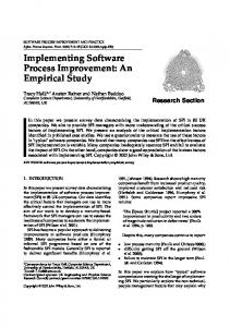
For the remaining artifacts, we assigned the available material to the tentative document structure to check its feasibility. The outcome of the analysis is the (minimal) process requirements artifact (Figure 3), which is defined in ArSPI as follows: A
K ka
t
om de Artifact Definition—The Process Requirements (PRQ) comprise all information regarding the m goals, stakeholders, requirements, basic conditions, and technical infrastructures. Furthermore, the me isc rz h ie e process requirements comprehend an overall process draft, which briefly describes the expected lle V target process. The input for the process requirements is given by a long-term road map, issues and En ers tw ion change requests from projects, further external requirement sources, or process audits/assessments. ic n kl ur Since process improvement usually addresses already deployed processes, the process requirements un f g ür always relate to an actual process. is U ts
tr MagicDraw UML,model 1-1 /Users/kuhrmann/Documents/Research/CC-Processes/Publikationen/2013/IST (SPI)/Preparation/SPI-Blueprint/SP The UML in Figure 3 shows that all elements must be covered in the requirements (1..*). A
ka explicit in order to enable The intention behind this design decision is to make all the requiredK parts the process engineer to ask for corresponding information. Even if, mforminstance, the actual SPI er isc this particular topic project does not aim to implement or customize a technical infrastructure, zi he el should still be discussed. A simple statement “not yet relevant” in the respective subsection of le Ve En rs a process requirements document is then enough to fulfill requirements regarding tw ionthe structural ic n completeness of the artifact. k u
de Akademische Version nur für Unterrichtszwecke, Kommerzielle Entwicklung ist strengstensom untersagt
lu r ng fü U is rprocess 4.3.5. Developing the Conceptual and Technical Process Design Artifacts. Regarding the t s nt tre eP4, r designs, we found two settings. The projects (Table VIII) either had an integrated artifact (P2, Ak ng rich P5) in which concepts, designs, and technical aspects were summarized, or the projects had separate Ko a d st ts en zw e m (P1, conceptual designs and technical designs m mis P3). Furthermore, in P1 the respective information s u ec er P3cexplicitly defined a design concept and a realization n ke was scattered across several artifacts, while zi he te el rs concept. le Ve ag En rs t The objective of the analysis was thus to answer the question: What information must a process tw ion ic nand technical aspects? We performed the design comprise and how do we have to handle concepts kl ur un f following steps to develop the design artifacts: g ür is Un t s t and the technical parts 1. For the integrated designs (P2, P4, P5) separate the concepts tre err ng icstructure (a) Structure the concept parts and develop an initial artifact st hts zw enstructure (b) Structure the technical parts and develop an initial artifact s ec un k te e rs Evol. and Proc. (0000) c 0000 John Wiley & Sons, Ltd. Copyright J. Softw. ag Prepared using smrauth.cls DOI: 10.1002/smr t
12
M. KUHRMANN
2. 3. 4. 5.
Compare the tentative concept artifact with the corresponding one from P3 and refine Compare the tentative technical artifact with the corresponding one from P3 and refine Map and assign the information from P1 to the respective tentative artifacts and refine Analyze the dependencies between the resulting artifacts and check, whether: (a) Can all conceptual designs be assigned to respective technical parts? (b) Can all technical realization decisions be assigned to a design decision?
package Data [
CPD-TPD ]
6. Consolidate the artifacts and connect them to the process requirements tszwecke ion nur für Unterrich Akademische Vers ns untersagt icklung ist strengste Kommerzielle Entw
Requirements
tszwecke ion nur für Unterrich Akademische Vers ns untersagt icklung ist strengste Kommerzielle Entw
Goals 1
tszwecke ion nur für Unterrich Akademische Vers ns untersagt icklung ist strengste Kommerzielle Entw
Process Conceptualization and Design
Process Realization
«SPIDocument» Conceptual Process Design
«SPIDocument» Technical Process Design
0..*
Metamodel Adaptations
Logical and Physical Model Organization
Principles 0..1
Variability Operations Planned Adaptations
1 Organization And Role Model
New Role
0..* 0..*
0..* rrichtszwecke Version nur für Unte ns untersagt icklung ist strengste Kommerzielle Entw
Removed RoleAkademis che 0..*
0..1 0..*
tszwecke ion nur für Unterrich Akademische Vers ns untersagt icklung ist strengste Kommerzielle Entw
tszweck ion nur für Unterrich Akademische Vers ns unte icklung ist strengste Kommerzielle Entw
Grouping and Categorization
0..*
Customized Role
refines
Organization and Role Model Realization 0..*
Artifact Model
New Artifact
Integrated Organization Model
0..* 0..* 0..1
Customized Artifact
Integrated Role Model
Removed Artifact 0..*
Artifact Model Realization
refines Artifact Dependencies 0..*
0..* 0..*
Process Model
New Process Part
0..*
0..* Artifact to Artifact Dependencies Integrated Artifact Model
Artifact to Role Dependencies Artifact to Process Part Dependencies
ts ion nur für Unterrich Akademische Vers icklung ist strengste Kommerzielle Entw
0..* Customized Process Part 0..* Removed ProcessPart
0..*
tszwecke ion nur für Unterrich Akademische Vers ns untersagt icklung ist strengste Kommerzielle Entw
0..*
rrichtszwecke Version nur für Unte t AkademischeRole strengstens untersag to Process Part ist Dependencies icklung Kommerzielle Entw 0..* refines
0..*
Overall Process
0..*
Additional Requirements 0..1
0..* 0..*
Process Documentation Model
0..*
0..1
refines
Supporting Material Model
refines
Process Model Realization 0..*
Birds-Eye Perspective Milestones
Integrated Process Model
Milestone to Artifact Dependencies Milestone to Process Part Dependencies
Process Documentation Model Realization
has requirement tracing Supporting Material Model Realization
0..1
0..*
tszwecke ion nur für Unterrich t Akademische Vers Tracing ns untersag gsteRequirements icklung ist stren 1 Kommerzielle Entw
ion nur für Unt Akademische Vers icklung ist stre Kommerzielle Entw
Tailoring Model Realization tszwecke refines ion nur für Unterrich Akademische Vers ns untersagt icklung ist strengste Kommerzielle Entw
Tailoring Model
1..*
1..*
Tailoring Configuration 1
Tailoring Modules 1..*
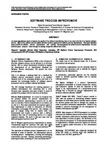
Figure 4. Structure of the process design artifacts.
The outcomes of the conceptualization are the conceptual process design and the technical process design artifacts (Figure 4), which ArSPI defines as follows: Artifact Definition—The Conceptual Process Design (CPD) comprises the information regarding the design principles, the planned adaptations (regarding the process assets forming the process model, e.g., artifacts, roles, process parts), requirements regarding process documentation, supporting material, and process tailoring. All designs that are made in the CPD are technology independent in order to be applicable to different realization platforms. The CPD artifact serves as input for the technical process design and the process life cycle support. Artifact Definition—The Technical Process Design (TPD) refines the conceptual process design and adds technical information. For instance, if a new artifact was designed in the CPD in the c 0000 John Wiley & Sons, Ltd. Copyright Prepared using smrauth.cls
J. Softw. Evol. and Proc. (0000) DOI: 10.1002/smr
ion nur Akademische Vers icklung Kommerzielle Entw
13
CRAFTING A SOFTWARE PROCESS IMPROVEMENT APPROACH
TPD all information is added in order to be able to realize the artifact using a particular processengineering framework—the artifact is refined to a data structure that can be realized by the process engineer. The TPD comprehends the refined information regarding the planned adaptations, process documentation, and training material. In addition, the TPD also contains a fine-grained tailoring model (if tailoring was demanded), which contains the definition of tailoring modules and tailoring configurations. If necessary, the TPD also contains information regarding required technical customizations of the selected process-engineering framework, e.g., the customization of the framework’s metamodel. The contents of the TPD influence the process life cycle support documentation. Technical Process Design – 1 Conceptual Process Design
SPEM-based Process
Process Design
EPF Infrastructure
Process Model
Technical Process Design – 2
Defined Infrastructure V-Modell XT-based Process
V-Modell Infrastructure … Standard profile: 2-staged design process ! multiple realizations, work distribution…
Tailored profile: defined infrastructure ! simplified artifacts
Figure 5. Artifacts in the design process.
Design Decision: For the process design, we decided to rely on a 2-staged design process that separates the conceptualization activities from the technology-specific realization activities. With this design decision, we basically allow for separating the conceptualization and the realization phases of SPI projects. However, from the repository analysis we learned that an integrated approach is also required. Therefore, we designed the two design artifacts in a manner that allows for integrating them into one artifact (the respective guideline and a sample template can be depicted from the ArSPI website). Figure 5 shows the conceptual perspective of the artifacts in the design process (Figure 4). The standard profile (left) separates the conceptual and the technical design steps to allow for multiple realizations, or to support work distribution. The tailored profile (right) provides a simplified approach, e.g., for smaller SPI projects. The conceptual and the technical process design are integrated into a process design artifact. For instance, if the technical infrastructure—the process-engineering framework— is defined the process design can explicitly target the selected framework and, thus, the integrated process design artifact can be used (disadvantage: the realization platform is fixed). If the realization platform is going to be defined in the project, the 2-staged design process can be used to (1) create the concept and then to (2) define the realization platform. This approach can also be used to conduct research, e.g., to conduct comparative case studies (Section 4.4.1). Insights into the Detailed Artifact Construction Process As an example, in the following, we describe the process of developing the conceptual process design (Figure 4) in detail. In the comparison, we found that all designs put special emphasis on the outcomes of the process design process (artifacts, or work products). Likewise, properties for the artifacts and their relation to, e.g., roles or milestones, were present in every design artifact. For P2-P5, we found very detailed tables with artifact lists naming new artifacts, artifacts to be removed from the reused reference process, and artifacts to be customized. We found the same structure for the roles and the processes/workflows. To this end, we defined the composite artifact “Artifact Model” that deals with the artifact model of the intended process and comprises information regarding new, removed, and customized artifacts, and also regarding the dependencies between the artifacts, e.g., dependencies c 0000 John Wiley & Sons, Ltd. Copyright Prepared using smrauth.cls
J. Softw. Evol. and Proc. (0000) DOI: 10.1002/smr
14
M. KUHRMANN
between artifacts, dependencies to roles and milestones. We decided to use this structure as a pattern and also applied it to the roles and to the process model. Information regarding other process parts, such as tailoring, or requirements regarding the structure and the design of the (electronic) process guide did not allow for creating such a pattern. However, we decided to follow our design approach for those parts, too (not shown in Figure 4). In order to link the contents of the conceptual process design, we then analyzed the process requirements for appropriate interfaces. We decided to share the goals artifact from the process requirements, created an explicit dependency regarding the contents, and added a requirements tracing artifact to the conceptual process design. That is, the requirements can be transferred to the design and the designs can also be backtracked to the original requirements. We applied the same procedure to the technical process design by linking the contents to the conceptual process design and by sharing the requirements tracing artifact. Furthermore, “*-Model” artifacts of the conceptual process design are linked to the respective “*-Model Realization” artifacts of the technical process design (Figure 4) to ensure that every realization-related decision is assigned to a design. In addition, we also added parts explicitly dealing with technical questions, e.g., particular tailoring models that are specific to the used process-engineering framework or required metamodel adaptations. Furthermore, if tailoring is required for a process then the detailed (technical) configuration for the tailoring is defined here by assigning artifacts or processes to particular tailoring configurations. In order to allow for flexibility, the design (Figure 4) shows that, e.g., the artifact conceptual process design comprises several sub-artifacts of which the goals, the requirements tracing, and the planned adaptations are mandatory (cardinality 1), whereas the respective contents are optional (0..1, or 0..*). For instance, if a process does not need to introduce new roles the sub-artifact organization and role model is not required. If new artifacts need to be designed in an SPI project, then the sub-artifact artifact model must be instantiated that contains all new artifacts, e.g., in a table naming and describing them. In consequence, the model allows for the design of fully-fledged processes as well as for the design of process parts only, e.g., organization models or artifact models. 4.3.6. Developing the Process Life Cycle Support Artifact. Our analyses showed the demand for an artifact supporting the life cycle of a process model, which is part of a company-wide process ecosystem. In the analyzed projects, we found one explicit life cycle support documentation artifact and several artifacts addressing selected aspects of the life cycle, such as guidelines for authoring tools, deployment plans, training plans, or measurement strategies. The analysis of these artifacts aimed to answer the following question: Which information is necessary to support the deployment and the long-term maintenance of a software process at the organization level? To this end, we performed the following steps: 1. Collect and generalize all artifacts (from the repository analysis and from external sources) 2. Define the minimal set of activities to be performed for deployment and maintenance 3. Develop an artifact that serves as container to collect and document all these activities Based on project P2, we decided to design an integrated process life cycle support artifact that, at least, comprehends sub-artifacts addressing training, measurement and evaluation, deployment and further development, and change management (Figure 6). The main purpose of these artifacts is to define strategies, e.g., for training, and to define particular procedures, e.g., for the change management, that have to be established at the organization level. ArSPI defines the process life cycle support documentation as follows: Artifact Definition—The Process Life Cycle Support (PLC) comprises all definitions and documentation required to deploy and manage the developed process. Therefore, the PLC contains information regarding the training of the process, the deployment and further development, the measurement and evaluation strategy, and the change management. The PLC is the input artifact for several further planning artifacts, e.g., training plans or evaluation plans. Furthermore, the PLC is used to configure the company-wide software process management in order to address the needs c 0000 John Wiley & Sons, Ltd. Copyright Prepared using smrauth.cls
J. Softw. Evol. and Proc. (0000) DOI: 10.1002/smr
package Data [
PLC ]
15
CRAFTING A SOFTWARE PROCESS IMPROVEMENT APPROACH
cke nur für Unterrichtszwe ersagt Akademische Version ngstens unt stre ist g klun wic Ent lle Change Kommerzie
Process Life Cycle Management «SPIDocument»
zwecke Process Life Cycle Support nur für Unterrichts Akademische Version s untersagt klung ist strengsten wic Ent lle rzie me Kom
Change Management
contains 0..1
Deployment and Further Development contains
Roadmap 1
0..1
1
1..*
0..1
contains
creates
Deployment Strategy
Measurement and Evaluation
1
1 1
«SPIDocument» Deployment Plan
0..*
«SPIDocument» Measurement Plan
creates
Measurement and Evaluation Strategy
0..1
1..*
1..*
creates 1
0..*
1..*
1..*
«SPIDocument» User Evaluation Plan
Metric Catalog 1..* 1..*
cke nur für Unterrichtszwe Akademische Version s untersagt klung ist strengsten wic Ent lle rzie me Kom
cke Metric nur für Unterrichtszwe agt Akademische Version ist strengstens unters g klun wic Ent lle Kommerzie contains
Training 0..1
creates
Training Concept 1
0..*
1
0..*
«SPIDocument» Training Plan
Figure 6. Structure of the process life cycle support artifact and selected related artifacts.
of the developed process and, thus, also contains changes/additions of organization processes, e.g., configuration management for a reference process. The life cycle support affects a number of organization processes and units, e.g., a companyzweckeneed to wide release management needs to be established for the new process. Feedback loops nur für Unterrichts ersagt Akademische Version g ist strengstens unt klun wic Ent lle rzie Komme be established inckeorder to collect change/feature requests regarding the process, which need to be zwe chts erri Unt nur für Akademische Version s untersagtmanagement. That is, that the resulting artifacts are highly interconnected with tenchange ngsa handled by klung ist stre Kommerzielle Entwic the other elements of ArSPI, e.g., a training concept causes the creation of training material (also for different stakeholders [2]) and training plans and, finally, is specific for a particular release of the process (for instance, for the V-Modell XT reference model, different trainings had to be created for the releases 1.2 and 1.3, as the technical changes substantially affected the process as such). 4.3.7. Remaining Artifacts and Methods. Beyond the previously described artifacts, ArSPI comprehends more artifacts and basic processes to create an integrated model; most of them are optional depending on the context. In this section we briefly describe the remaining artifacts by Unterrichtszwecke we example, explain why they are part of the model, and how they Aka were integrated. Furthermore, e Version nur für demisch s untersagt klung ist strengsten wic Ent lle rzie me Kom give an example regarding the processes behind the artifacts. cke zwe chts erri Unt für nur agt named the major artifacts from the repository analysis. However, we Akademische Ver s unters ngstenwe InsionTable VIII, only klung ist stre Kommerzielle Entwic identified further artifacts that were created in the specific contexts. For instance, in the projects P2 and P3, requirements demanded the documentation of all applied variability operations [52, 28] to aid the determination of the level of conformance to a reference model. To this end, a tool-generated report was created, which we generalized to the SPL-Delta report. This report addresses projects in which a process is created that is based on a process line. The report is linked to the measurement and evaluation strategy and to the technical process design and names all applied variability operations. When it comes to an assessment (part of the measurement and evaluation strategy), the report can be used to show that, e.g., a specific role is just a renamed extension of a standard role (technical realization decision) thus easing the assessment. In the same way, we also integrated artifacts and structures for, e.g., quality management, project management, and so forth. Design Decision: Among all artifacts defined by ArSPI, 5 artifacts are marked to be mandatory (Section 3), which means that these artifacts have to be created in every SPI project. The decision, whether an artifact is mandatory or not, was made according to the life cycle phases analysis, conceptualization, etc. (Figure 1). Every phase puts emphasis on specific work, e.g., the analysis of a process and the elicitation of the requirements. Having made good experiences with the concept of decision gates as implemented in the V-Modell XT, we applied this pattern to ArSPI by explicitly defining artifacts that need to be delivered and c 0000 John Wiley & Sons, Ltd. Copyright Prepared using smrauth.cls
J. Softw. Evol. and Proc. (0000) DOI: 10.1002/smr
16
M. KUHRMANN
Table II. Selected top-level key activities of the ArSPI model and related input/output artifacts. Activity
Input
Output/Modifies
Create Process Requirements (composite activity)
(output from) Analyze Actual Process (output from) Analyze Vision Process Assessment Process Requirements
Process Requirements
Create Conceptual Process Design (composite activity) Analyze Conceptual Process Design (glue activity)
Conceptual Process Design
Conceptual Process Design Technical Process Design Process Life Cycle Support
quality assured at a certain point in a project. To this end, each increment of a life cycle phase is completed by a quality assured version of a mandatory artifact, e.g., completing an analysis-iteration requires a version of the process requirements artifact. An implication of the artifact-based design approach is that activities/methods used to create the respective artifacts are usually left open to allow for flexibility in the artifacts’ creation processes. However, in order to create a meaningful model, we needed to create a minimal set of activities, e.g., to allow for project planning. These are defined as exemplarily shown in Table II. For all toplevel artifacts, we defined composite activities that serve as work packages producing the respective artifacts. The single steps of the composite activities can be done by, for instance, using the methods named in Table IX. Furthermore, we defined glue activities that link the top-level artifacts, e.g., analyze conceptual process design, which takes the conceptual process design and produces the first contents for the technical process design and the process life cycle support thus serving as “set up” activity for the creation processes of the respective artifacts. Further fine-grained activities were defined in a dependency-driven approach: for every dependency, we checked whether the dependency causes activities to be performed in a project and defined an initial set of such activities. 4.4. Step 2: Internal Validation and Consolidation The internal validation of our SPI approach was initiated in 2011 for the purpose of evaluating the approach regarding its general applicability before applying it to real-world projects that aim to improve (critical) processes. Based on the results of the validation, the approach should be consolidated. The validation and consolidation process comprised three steps: 1. Internal validation in a student lab (controlled environment, reported in [25], Section 4.4.1) 2. Stepwise application in practice (Section 4.4.2) 3. External evaluation by selected experts (interview, Section 4.4.3) In the following, we describe the steps and the outcomes, or summarize the key results if already published. 4.4.1. Internal Validation in a Student Lab. The internal validation aims to create an experimental setting to conduct research on SPI in general and to validate the early version of ArSPI in particular, and to develop the instruments to be used in future external validations. Furthermore, the internal validation lays the foundation to replicate case studies in other contexts. The goal of the lab was to analyze whether the artifact-based improvement approach defined by ArSPI positively influences SPI. The lab was conducted in the context of the course “Software Engineering Processes” [26] in 2011/2012. A detailed research design regarding the development of the quasi-experiment (according to Wohlin et al. [54]), applied research methods and instruments, and the outcomes can be depicted from [25]. In this section, we only give a brief overview on the lab, summarize our findings, and discuss the impacts on the consolidation of ArSPI. In the student lab, two groups of students worked on the analysis, design, and realization of an improvement of a given software process. The experiment comprised a number of workshops in which the process was analyzed (context: artifact process requirements, Section 4.3.4) and c 0000 John Wiley & Sons, Ltd. Copyright Prepared using smrauth.cls
J. Softw. Evol. and Proc. (0000) DOI: 10.1002/smr
17
CRAFTING A SOFTWARE PROCESS IMPROVEMENT APPROACH
designed (context: process design artifacts, 2-staged design, Section 4.3.5), a session in which the process design was implemented using the artifact-based V-Modell XT framework and the activitybased Eclipse Process Framework (context: artifact process release), and finally a session in which the outcomes were evaluated from the perspective of the process engineers as well as from the perspective of the process users (context: measurement and evaluation, Section 4.3.6). Discussion of Key Results Figure 7 summarizes the results from the assessments. Since the results are manifold and discussed in detail in [25], we only briefly discuss one key finding relevant to the context of this article. Our results underpin the artifact-based design strategy—on which ArSPI is based—to be an advantageous instrument for process engineers (the transfer of designed artifacts into the authoring environment is “more” straightforward), whereas process consumers do not evidently care about the selected design strategy. However, as we found indication regarding the benefits of the artifact-based design strategy, we, for now, considered ArSPI to be a meaningful approach heading in the right direction that is worth further investigation. Furthermore, regarding the construction procedure, initial empirical data could be collected and the developed evaluation material was considered useful thus serving as input for further case studies (Section 4.5.2). Also, the general approach to (1) analyze the process requirements, (2) design the improvement without paying attention to technical environment, and (3) defining the mapping to the concrete environment showed beneficial—the platform-specific concepts both rely on the same conceptual design, which makes the resulting processes comparable. Regarding the ArSPI model as such, only few minor issues regarding the dependencies between the artifacts were identified and fixed. Q1-13: Completeness overall process
6,5 6,4
Q1-12: Completeness activities
6,5 6,6
Q2-1: HTML export completeness 7,00 Q2-11: Process consistency
Q1-11: Completeness relationships
6,2
7 6,6
Q1-9: Completeness roles
7 6,8
5,00
4,67 5,00
4,00 4,20 Q2-10: Implementation adequateness
7
Q1-10: Completeness artefacts
Q2-2: HTML export accessibility
6,00
6,00
4,67 6,67
3,00
1,00
Q2-9: Completeness activities
6,33
Q2-3: Overall process presentation
3,80 6,00
2,00
4,75
3,80
3,00
0,00 4,00
4,40
6,33
Q2-4: Process verifiability
5,20
5,67
Q1-8: Overall completeness of artefacts
6 6,2 0
1
V-Modell XT
2
3
4
5
6
7
EPF
7,00
Q2-8: Completeness relationships 6,20
6,00
Q2-5: Implementation completeness
7,00
6,67 Q2-7: Completeness artefacts
Q2-6: Completeness roles
EPF
V-Modell XT
Figure 7. Results from the internal validation (left: process engineers, right: process consumers perspective).
4.4.2. Stepwise Application in Practice. We applied parts of ArSPI in practice with the purpose to validate the feasibility of selected elements in a practical setting without deploying the whole ArSPI approach. Table VI summarizes the two projects in which we applied our model. Context When it came to the validation, project P2 was completed and the resulting process was deployed and in use. The company owning P2 now maintained the process and initiated a long-term improvement program. We selected P2 for applying selected ArSPI artifacts for the purpose to (1) validate the general applicability, (2) get insights into the practical application, and (3) investigate the particular materialization of artifacts and methods generally described in ArSPI. Project P6 was initiated in mid 2011 and aimed to improve a company-specific software process. Same as for P2, the process of P6 should be based on the V-Modell XT Bund (Table V). In the following, we briefly describe the elements of ArSPI that were applied in these projects. As due to the nature of the projects and of the performing organizations a formal measurement strategy could (yet) not be established, we cannot provide a detailed empirical analysis, but provide an informal retrospective. c 0000 John Wiley & Sons, Ltd. Copyright Prepared using smrauth.cls
J. Softw. Evol. and Proc. (0000) DOI: 10.1002/smr
18
M. KUHRMANN
Applying ArSPI in Project P2 Project P2 contributed to the development of ArSPI and, therefore, the stepwise application was straightforward. In detail, artifacts that were already created in previous SPI activities were analyzed again. In a second step, artifacts based on ArSPI were developed in parallel and then replaced the original ones: • The integrated process design replaced a “realization concept” • The process life cycle support replaced a “process engineer handbook” • The SPL-delta report updated a comparable, but differently structured document of the same name
Since the process of P2 was ‘relatively’ compact, we decided to integrate the artifacts conceptual process design and technical process design according to the tailoring profile defined by ArSPI. In the process life cycle support, we found instructions regarding the process maintenance and its deployment. Further material, e.g., explicit deployment plans, measurement and evaluation strategies, could not be found. Therefore, a deployment plan was created and integrated in a new change management platform. The change management platform was until then a simple list managed in a SharePoint Services web portal. In order to establish the long-term strategy, we installed an integrated web application (IceScrum, http://www.icescrum.org) that is now used to support change management, release planning, requirements engineering (represented by user stories in the tool), and some project management (e.g., feature-release assignments). Using this tool, the company deployed the basic management procedures and artifacts required by ArSPI. A major flaw in P2 was the absence of a formal evaluation strategy. For organizational and legal reasons, such a strategy is hard to establish. However, in 2013 such a strategy was then initially defined and is going to be established in mid 2014 with a baseline measurement. Key element of the strategy is the evaluation approach developed in the student lab (Section 4.4.1). For the perspective of the process consumers, stakeholder groups were defined, e.g., process owners, contractors, and developers. These groups shall provide specific feedback to support the improvement of the process. Applying ArSPI in Project P6 In project P6, a new process variant, based on the V-Modell XT Bund, should be developed. The audiences of the intended process are the contracting authorities and the software developers, who were especially interested in the integration of agile methods. As the project setting was similar to P2, we applied the same setup to P6. In contrast, we introduced the selected ArSPI key artifacts from the very beginning on. The process requirements were developed in advance as an integrated Word document. Based on these requirements, we developed the integrated process design (for the size of the project, we again used the integrated artifact). Having made good experiences with the process life cycle support in P2, we recommended the client a corresponding artifact. The offer was accepted and proved beneficial, as the client planned to set up an own build environmentk on which the local process engineering group can maintain the process, and create and deploy new releases. The necessary procedures (e.g., handling of the infrastructure, maintaining the process, creating releases and deployment packages, or access to the “Avatar”∗∗ ) were documented in the process life cycle support. Finally, when P6 was completed, the resulting process, the entire infrastructure, and the complementing project documentation was shipped to the client, who now maintains its process himself. Again, for organizational and legal reasons a measurement and evaluation strategy could not yet be defined. However, using ArSPI in P6 came close to a case study. Although we could not collect and analyze data, we experienced the value of the approach (especially the document templates and the dependency model, which eased setting up the build environment in terms of assessing whether all required process assets are correctly assembled) and developed a feeling for later
k The
V-Modell XT is assembled using an Ant-based server infrastructure that creates complete installers that process consumers can use, and that comprise the process model, process documentation, tools, training material, etc. The VModell XT calls this server-side infrastructure “build environment”. ∗∗ The Avatar is a twitter account that the process group uses to post updates. The virtual person that owns the account is also the protagonist in the process-integrated guideline providing new process users with “first steps”. c 0000 John Wiley & Sons, Ltd. Copyright Prepared using smrauth.cls
J. Softw. Evol. and Proc. (0000) DOI: 10.1002/smr
19
CRAFTING A SOFTWARE PROCESS IMPROVEMENT APPROACH
projects and how to integrate them with case study research (Section 4.5.2). Furthermore, based on the experiences, ArSPI as such was extended by some tool-related classes, e.g., Process Tools as general element, and Assistance Tools as part of a delivery package. 4.4.3. Conducting an Expert Evaluation. Although having validated ArSPI in a student lab and having partially applied it in practice, we still needed an external evaluation before finally disseminating the approach. Hence, we decided to evaluate ArSPI with a small set of experts using the instrument interview. The goal of consulting the experts was to gather feedback and to get an external rating of the usefulness of the ArSPI core components. The goal of the interviews is to create a baseline measurement, which is not purposed to be a generalizable empirical finding. Data Collection and Analysis We consulted four external experts from academia and industry, which we personally invited for an interview. The experts were carefully selected from different software engineering domains with at least 5 years of experience. Expert 1 deals with optimizing quality assurance procedures in an industry context (small SPI). Expert 2 works in the requirements engineering domain as a researcher and in industry context, especially on improving requirements engineering processes. Expert’s 2 contexts are SPI projects, which rage from 5- to 100-person months effort that we classify as “medium” and “large” SPI. Experts 3 and 4 work in SPI in general, and both are experienced in industry and government context. Both experts deal with SPI projects spanning several years that we classify as “large” (expert 3 and 4) and “very large” (expert 3). Before the interview, the experts were given a definition of the ArSPI model [23] and a list of related questions that they would be asked during the interview. In a one-to-one interview, the researcher filled out a questionnaire with the expert. Interviews were conducted either on the telephone or face-to-face and lasted approximately 60 minutes. The experts answered a set of closed questions in the form of a structured questionnaire; comments were recorded in free-text fields. The questionnaire named all together 78 artifacts (top-level and comprised sub-artifacts). A free-text field was provided for every list item to get feedback or explanation. For each expert, an individual rating (based on school grades) was computed, and in addition the mean of all ratings was computed to relate the individual ratings. Based on the experts’ comments, we then qualitatively analyzed and interpreted the ratings (due to the limited number of subjects). Discussion of Key Results Table III shows the results from the questionnaire regarding the rating of the importance of the ArSPI artifacts. All experts agreed on the importance of the process requirements, the conceptual process design, and the process release (2.0 or better). Also, the process life cycle support was considered important. All experts agreed on the usefulness of the process requirements and the conceptual process design—regardless of their personal context (see above). Expert 1 rated the process requirements and the conceptual process design to be important (1.7 and 1.5). Expert 2 gave the same evaluation. Expert 3, who is experienced in software process lines, rated the process requirements (1.5) and the process life cycle support (1.7) slightly better than the other experts. Both, expert 3 and expert 4, agreed on the importance of the process release (1.0), which they rated to be more important than the other two experts (2.0). All experts rated the technical process design little important (2.6 – 3.1). The experts 1, 2, and 4 explained that this artifact was yet not that relevant in their contexts, e.g., expert 2 explained that process realization is usually not part of his projects. Table III. Expert rating on the ArSPI key artifacts (1.0: very important – 6.0: not important at all). Artifact Process Requirements (PRQ) Conceptual Process Design (CPD) Technical Process Design (TPD) Process Life Cycle Support (PLC) Process Release (PR) c 0000 John Wiley & Sons, Ltd. Copyright Prepared using smrauth.cls
Expert 1
Expert 2
Expert 3
Expert 4
Mean
1.7 1.5 3.1 2.0 2.0
1.7 1.5 3.1 2.0 2.0
1.5 1.5 3.0 1.7 1.0
1.8 1.8 2.6 2.3 1.0
1.7 1.6 3.0 2.0 1.5
J. Softw. Evol. and Proc. (0000) DOI: 10.1002/smr
20
M. KUHRMANN
Beyond the general usefulness of the artifacts, we also asked the experts whether they ever created all artifacts proposed by ArSPI. If we found an artifact that was not created, we asked the experts whether the absence of this artifact caused problems, or whether they think the artifact is just unimportant. A simplified visualization of the outcome is shown in Figure 8. In the figure, a color-coding is used to highlight artifacts (and comprised sub-artifacts) that were not created by the interviewees. In summary, we could only find 7 artifacts that were mentioned unimportant. On the other hand, we could identify 27 artifacts that were rated basically important, and we could find 13 artifacts that the interviewees missed in their projects. Conceptual Process Design Principles Planned Adaptations Org. and Role Model
Removed roles Grouping and cat. Artifact Model
Technical Process Design Log. And Phys. Model Organization Metamodel adapt. Variability operations Org. and Role Model Realization Integr. Org. model integr. Role model
Process Requirements Goals Stakeholder and Roles Requirements Overall Process Draft Technical Infrastructure Basic Conditions
Legend important and missing important, but not missing not important at all used artifact
Artifact Model Realization Process Release
Removed artifacts Artifact Dependencies Art.2Art. Art.2Role
Process Model Realization
Proc. Doc. Model Realization Sup. Material Model Realization
Process Model
Removed processes Overall Process Bird's Eye
Tailoring Model Realization Tailoring modules Tailoring configurations
Process Life Cycle Support Milestone Role2Proc.
Related Plans
Training
Training Plan
Depl. And Further Development Deployment Strategy Roadmap
Deployment Plan
Process Documentation Model Customized material Removed material Supporting Material Model New material Customized material Removed material
Change Management Measurement and Evaluation Meas. And Eval. Strat.
Measurement Plan User Evaluation Plan
Tailoring Model Requirements Tracing
Figure 8. Simplified visualization of the outcomes of the expert interviews.
The analysis served two purposes: (1) Artifacts that are mentioned important and their absence has no impact shall be subject to tailoring. The ArSPI model has to provide enough flexibility to skip such artifacts. (2) The ArSPI model shall provide the process engineers with all support necessary to successfully conduct SPI. Therefore, artifacts that the interviewees missed in their project should be part of ArSPI to address resulting problems, such as a missing deployment plan leading to confusion. In the following, we only discuss the second aspect (missing artifacts that caused trouble), as the first one is inherently given by the design of the ArSPI model (Section 4.3.3). For instance, expert 1 and expert 4 considered the overall process draft (in the process requirements) to be important and complained that the big picture of the target process is often missing and, therefore, causes confusion and conflicts. Expert 2 named the role to process part dependencies (in the conceptual process design) to be important and explained that missing information regarding this aspect caused problems in one of his projects. The experts 2 and 4 named the deployment strategy (in the process life cycle support) to be important and gave examples from their projects in which a missing strategy caused serious trouble (two competing methods were rolled out at the same time and the process consumers did not know which of the methods was the one that counted). Related to the deployment strategy is the deployment plan, which was also considered very important especially at the beginning of an improvement project to make transparent when a process release c 0000 John Wiley & Sons, Ltd. Copyright Prepared using smrauth.cls
J. Softw. Evol. and Proc. (0000) DOI: 10.1002/smr
CRAFTING A SOFTWARE PROCESS IMPROVEMENT APPROACH
21
will be available. Expert 4 missed the measurement and evaluation strategy (and the related plans) and explained that “it does not make sense to improve processes without having an idea how to determine the improvements” and, furthermore, complained that in his actual context the feasibility of SPI is often not measured at all. The outcome of this finding supported the refined designs from the internal validation and the stepwise application. Depending on their respective context, the interviewees have different requirements regarding an SPI approach, which ArSPI addresses via its tailoring-affine design (we did not need to remove artifacts, as all “critical” artifacts are subject to tailoring). Regarding the usefulness, the interview indicates ArSPI to be useful, as it also covers artifacts that the experts missed and experienced to be critical. All experts considered ArSPI to be complete and consistent. 4.5. Step 3: Dissemination into Practice The final step in the construction procedure is the dissemination into practice. To this end, we collected all the material developed during the previous steps and integrated it into the following dissemination strategy: • Publish the ArSPI model and provide support material, such as training material and guidance • Prepare and conduct further empirical studies
The goal is to disseminate ArSPI and to lay the foundation for further research activities. In the following, we describe the particular activities and outcomes created so far. 4.5.1. The ArSPI Model and Support Material, Training Material and Guidance. Since ArSPI is designed to serve small, medium, and large SPI projects, it bears an inherent complexity. To this end, we also designed training material and guidance. The training material is, so far, addressing the education of process engineers. We designed a course on software process modeling [26] that was successfully implemented multiple times. The key elements of the course are justified with ArSPI, e.g., the basic improvement cycle and some selected methods. Since the course design is also based on experiences gathered in practical trainings in industry, the course description can be easily transferred into practice. Although the V-Modell XT inspired the development of ArSPI, the approach in general is platform-independent and, therefore, the course design can be applied to arbitrary process frameworks. A specific instance of ArSPI addressing the V-Modell XT is described in the textbook [33], which is a detailed (technical) guideline for process engineers that cope with the V-Modell XT framework, and addresses the particular needs, e.g., detailed design and realization procedures, handling of the development environment, and discussing conformance criteria. In order to make ArSPI accessible, we created a web site on which we provide all ArSPI-related material. In detail: a technical report [23] that serves as “data sink” and contains the full artifact UML model, basic processes and detailed descriptions, and additional background information, scientific contributions on ArSPI, for instance [25, 26, 24], an initial implementation of ArSPI as a process model based on the Eclipse Process Framework, and document templates and templates for evaluation purposes, e.g., the evaluation material used in [25]. 4.5.2. ArSPI Pilot Application in Practice. So far, we developed ArSPI, internally validated it using a quasi-experiment in a student lab, and conducted an interview with experts. The next step was to conduct a case study in practice. A first case study was conducted in 2012/2013 (cf. [34, 24]). As case, we selected an SPI project in Eastern Europe (Table VII, project P7), the research design and the evaluation material was taken from the student lab that we described in Section 4.4.1. The objectives of the SPI project were general administrative tasks, as well as the development of business processes and the coordination of software development projects. We planned the SPI project as a 3-iteration project and tailored ArSPI accordingly. Iteration 1 should produce a technical prototype (demonstrator), iteration 2 should produce an initially integrated process release 0.9 that was used to establish the measurement strategy and to conduct a baseline measurement (Figure 9) and, finally, iteration 3 should produce the release 1.0 to be deployed to the process consumers. c 0000 John Wiley & Sons, Ltd. Copyright Prepared using smrauth.cls
J. Softw. Evol. and Proc. (0000) DOI: 10.1002/smr
22
M. KUHRMANN
Discussion of Key Results Figure 9 summarizes the results of the baseline measurement. The evaluation was done using questionnaires that comprised closed (Likert scale) and open (free text) questions. Subjects having either the role of the process owner or the lead developer of the processsupporting tools performed the evaluation. Results of the evaluation show that all subjects consider
Q2-1: PDF export completeness 7,00 7,00 7,00 6,00
7,00 Q2-11: Process consistency 7,00
Q2-2: PDF export accessibility 7,00
5,00 4,00 Q2-10: Implementation adequateness 7,00
3,00
6,50
7,00 Q2-3: Overall process presentation
3,00
7,00
2,00 1,00 0,00 Q2-9: Completeness activities 7,00
6,50
5,00 6,50
6,00 Q2-8: Completeness relationships
7,00
6,50 6,00
Q2-7: Completeness artefacts
7,00
Process Owner
Q2-4: Process verifiability
Q2-5: Implementation completeness
7,00 6,50 7,00
Q2-6: Completeness roles
Lead Development
Figure 9. Evaluation results from the external validation (by roles).
the delivered process to be complete and consistent (both with a rating of 7.00). The process owner’s rating mainly indicated that artifacts, activities, and relationships were missing in the release 0.9 resulting in respective change requests for, in total, 5 missing artifacts and related elements (e.g., relationships). The results of the rating via the questionnaires (which were developed in the student lab, Section 4.4.1) showed a successful application of ArSPI. The baseline measurement indicated to gaps in the release 0.9, which, using the ArSPI model, could be directly aligned to change requests (ArSPI model artifacts: change (Figure 6), process release, and process asset). Using the instrument case study, we could validate the ArSPI model, apply and refine the evaluation material, and gather experiences for the improvement of ArSPI. For ArSPI as such, no need for changes of the artifact model was identified, however, we found recommendations for the improvement of descriptions regarding the artifact creation process, e.g., to transfer the tables (used in the design process, Section 4.3.5) as best practice into the document templates and to add a corresponding method description to the ArSPI documentation. 4.6. Summary of the Construction Procedure and its Generalization We consolidate and generalize the construction procedure (Section 4.6.1), discuss limitations of the procedure (Section 4.6.2) and, finally, discuss our lessons learnt in Section 4.6.3. 4.6.1. Generalized Construction Procedure. Based on our retrospective systematization, Figure 10 shows the resulting generalized construction procedure that comprises the three areas knowledge management, internal validation and consolidation, and dissemination and evaluation, and lays the focus to the methods that were applied and showed feasible while developing ArSPI. In the knowledge management, we comprise all activities regarding the knowledge extraction (Section 4.3). The domain of interest is (initially) analyzed, e.g., using the instruments shown in Table I. We also consider activities regarding the conceptualization being part of the knowledge c 0000 John Wiley & Sons, Ltd. Copyright Prepared using smrauth.cls
J. Softw. Evol. and Proc. (0000) DOI: 10.1002/smr
23
CRAFTING A SOFTWARE PROCESS IMPROVEMENT APPROACH
Data Repositories Internal Validation and Consolidation
Knowledge Management
Data Repository Analysis
Artifact Method Data Pool Pool (project/ empirical)
Model Candidate
Empirical/ Project Data (Quasi-)Experiments
Research Design(s)
Expert Interviews Document Analysis
Pilot Projects (step-wise)
Systematic Literature Review
Model (Release)
(Quasi-)Experiments
External Literature Databases Case Study Research
Empirical/ Project Data Knowledge Management
Dissemination and Evaluation
Figure 10. Summarized construction procedure and template for further SPI and research activities.
management, as we—on the one hand—extract the knowledge from different sources, and—on the other hand—generate new knowledge that also needs to be managed. That is, outcomes of the conceptualization, e.g., UML models (Section 4.3.3) or templates, should be subject to the knowledge management, too. The synthesis of extracted knowledge forms a model candidate, which is subject to the internal validation and consolidation. In this stage, a model candidate is analyzed regarding its feasibility, e.g., using the instruments presented in Section 4.4. So far, we successfully applied the three methods quasi-experiment, expert interviews, and pilot projects. All these methods produced empirical data (in our context initial validation data or baseline measurements), which again are subject to knowledge management. Outcomes from the validation, e.g., empirical data, research designs, or evaluation material, can directly used in the following dissemination and evaluation step (Section 4.5). In this step, the model candidate is refined and consolidated to a model release that can be evaluated using case study research and also (quasi-)experiments, whereas due to the nature of the experiment instrument industry setups are hard to realize. To overcome this shortcoming, we suggest to use pilot projects to implement (parts of) an experiment, as pilot projects are often performed under “special” conditions. Finally, the model candidate as well as the model release are subject to the knowledge management and, thus, further improvement iterations start with an improved knowledge base. 4.6.2. Appropriateness and Limitations of the Approach. Figure 10 summarizes and links the different (empirical) instruments that we applied developing ArSPI. However, the figure presents a snapshot and lists only those methods that we applied. We now briefly discuss the appropriateness and the limitations of the chosen instruments in our context and potential risks for replication in other contexts. Data repository analyses and document analyses are accepted techniques to extract information. For instance, M¨unch et al. [21] consider such methods worthwhile. In line with O’Leary and Richardson [42], we also consider a systematic literature review worthwhile to get further information from external sources. However, we see two risks in these instruments: (1) the diversity of the data and (2) the sheer mass of information. To address these risks, a rigorous analysis schema is necessary to manage the information gathered from these steps. c 0000 John Wiley & Sons, Ltd. Copyright Prepared using smrauth.cls
J. Softw. Evol. and Proc. (0000) DOI: 10.1002/smr
24
M. KUHRMANN
In the internal validation, we combined different research methods. This decision showed beneficial, as every selected method has some specific flaws in our context that we could (partially) compensate by applying further instruments. For instance, a quasi-experiment was conducted in a lecture [25] and, thus, setting and context were controlled. By defining the context, we (automatically) introduced several threats to validity and, thus, the outcomes of the experiment are a baseline measurement indicating certain trends, but cannot be generalized. The same holds for the expert interviews, as we needed experienced experts that are able to understand and evaluate the model. For these reasons, we could only interview a very small group of experts that again only produced indication instead of generalizable data. Finally, the stepwise application showed a meaningful instrument. However, in our particular setting, we were not able to pilot our approach as fully-fledged case study and, thus, our first experiences in using ArSPI remain on a anecdotal level hard to transfer and generalize. A planned case study was then conducted in the dissemination step. In line with Raninen et al. [47], and Laporte and O’Connor [37], we consider this instrument as the most promising in order to get insights and to create empirical data. In summary, the presented combination of different (empirical) methods was successfully applied to craft the ArSPI model, to (internally) validate the model, and to disseminate the model. However, it remains unclear whether this set up can be repeated in other contexts. For instance, a small-tomedium enterprise has usually not enough resources to conduct experimentation-based research on the feasibility of SPI methods, as this instrument requires preparation, time, and subjects available for the experiment. On the other hand, case study research mostly aims to evaluate the software process to be improved, not the SPI method used to improve the process. That is, case study research only allows for indirect conclusions regarding the efficiency of the used SPI method. Therefore, in line with O’Leary and Richardson [42], we consider the combination of different instruments necessary if the research objective is the improvement of an SPI method. 4.6.3. Lessons Learnt from Crafting ArSPI. The previously described crafting procedure boils down about 8 years of conducting SPI and complementing research. We faced a number of challenges, which we discuss together with the essence of our lessons learnt in the following: Pragmatic vs. Systematic SPI ArSPI was developed accompanying several SPI activities. Since the main objectives were the processes to be improved and due to the parallel development of ArSPI, the construction of ArSPI was initially done in a pragmatic style rather than in a systematic manner (as done in [42] or [47]). For instance, the technical basis (e.g., process line metamodels, build environment) was deployed without a method that describes its use. The SPI projects conducted during the knowledge generation did not have appropriate research designs, e.g., even project P6 in the validation step was basically run as a case study, but was not designed as such. Learning: Pragmatic-driven SPI creates much knowledge, however, the risk of creating throwaway knowledge is high. During the knowledge extraction and conceptualization (Section 4.3), we experienced the challenge to extract (meaningful) knowledge from many different sources. Since no common knowledge base was available, we had to manually mine all information from internal and external sources, had to compare the findings and, again, had to validate our outcomes. Missing systematic research designs (apart from few exceptions) made it hard to ground design decisions and, thus, showed the need to conduct further research just for validating the ArSPI model itself. Internal Validation Getting empirical sound findings regarding the feasibility of ArSPI showed very challenging. In order to validate the ArSPI model, we had to implement a systematic and evidence-based approach. However, we faced the challenge that we wanted to validate the SPI approach itself and not the processes to be improved. To this end, we set up a controlled environment [25], applied ArSPI stepwise in practice, and consulted external experts. Learning: The internal validation was done using a quasi-experiment, which has several flaws by design, e.g., selection of cases and subjects, definition of the problem and the context, and the validity of the results. We learned that it is very challenging to set up a process-engineering lab and that we, usually, can only indirectly conclude whether effects in SPI are caused by the applied c 0000 John Wiley & Sons, Ltd. Copyright Prepared using smrauth.cls
J. Softw. Evol. and Proc. (0000) DOI: 10.1002/smr
CRAFTING A SOFTWARE PROCESS IMPROVEMENT APPROACH
25
approach. A positive finding: Such labs allow for developing research designs or evaluation material for later case studies (as for instance applied in project P7, Section 4.5.2). Anyway, we can use the findings of such an environment only as indicators, as the results are not generalizable. Furthermore, to find experienced experts that are willing to review a model and to conduct a one-hour interview beside their business showed challenging. Pilot Projects and Dissemination Armbrust et al. [2] present deployment strategies for software processes and mention that for a pilot application the “right” project needs to be found. Regarding the application of ArSPI in industrial settings we strongly support this statement, as we initially had no project at our disposal in which we could establish a fully-fledged evaluation strategy (Section 4.4.2). Instead, we stepwise implemented parts of the model to investigate the feasibility without a comprehensive research design. Until now, we could only create one complete instance of a case study. Learning: Findings and experiences from the pilot projects performed so far are anecdotal and hard to reproduce. However, when it came to the first “real” case study, having the approach itself, complementing research designs, templates, and baseline measurements (from the internal validation) at hand proved beneficial. In addition to an industry case study, university-hosted case study research in controlled environments also contributes to the improvement of exemplary software processes, however, their scope is often too limited to create enough “real” value [25, 26] for industry beyond gathering empirical data.
5. CONCLUSION In this article we provided insights into our research done in the context of the development of an artifact-based SPI approach. We briefly introduced the Artifact-based Software Improvement & Management (ArSPI) model to set the context and described its construction in detail. We gave insights into the construction procedure, which we finally distilled to the three areas knowledge management, internal validation and consolidation and dissemination and evaluation. We described our activities, the applied methods, the respective findings, and our experiences. A major goal of the construction procedure was to manage the shift from a pragmatically developed SPI approach toward a systematic and evidence-based managed and improved SPI approach. We thus gave also insights into our empirical work and the findings gathered so far. Furthermore, we discussed the major challenges we faced during the development of the ArSPI model. Our major findings are: A knowledge management strategy is crucial. We extracted our approach from a number of different sources in which the investigated artifacts were hard to compare and applied methods were hard to reproduce (in terms of selection and application of methods, decisionmaking processes, etc.). To overcome this shortcoming, a knowledge management needs to be established. Pragmatic SPI makes it hard to draw conclusions. On the one hand, we found plenty of project information, but, on the other hand, we barely found research designs. This situation made it hard to gather the “right” information from the repositories and to decide which of the findings really contributed to the respective project. Missing research designs made it hard to investigate the goals and the goal achievements, and also to find reference numbers to be used for later comparisons. Crafting the ArSPI model thus often required several additional steps, e.g., to consolidate artifact structures, without knowing whether a design decision was meaningful (which required additional and explicit validation work). Identifying the “right” pilot projects is hard. Beyond are purely—and limited—academic validation, the identification of SPI projects that are willing to apply a fully-fledged systematic approach, including measurement and evaluation, turned out very hard. Major reasons were of organizational and legal nature, e.g., the organizations performing the projects P2 and P6 feared an evaluation strategy, as it potentially also would allow for a benchmarking the c 0000 John Wiley & Sons, Ltd. Copyright Prepared using smrauth.cls
J. Softw. Evol. and Proc. (0000) DOI: 10.1002/smr
26
M. KUHRMANN
personnel, which is very critical for legal reasons. Just defining an evaluation strategy, as for instance done in P2, requires trust and still needs to be done very carefully. Combination of different methods produces usable results. ArSPI was developed using different instruments, such as repository and document analyses, surveys and interviews, and action research. Every applied instrument contributed to the overall approach and produced outcomes for later reuse, e.g., the research design of the lab can be reused by other researchers to independently replicate our work, the evaluation material developed in the lab was applied in practice (Section 4.5.2), and the questionnaire for the expert interviews can be used for further evaluations. Although not yet being generalizable, these instruments generated manifold data that can be used as baselines to conduct further research. In summary, the construction procedure itself produced material that lays the foundation for further research on SPI. Furthermore, the construction procedure provides an example, how a comprehensive method was derived from multiple sources, validated, and disseminated. Beyond the available literature and in line with [42], we give a concrete example of developing a method and share our experiences in selecting and combining the methods. Thus, practitioners can use our experiences when they face the challenge to select and/or combine particular instruments to improve their SPI approach, e.g., to extract information from different sources to create new artifacts. Furthermore, apart from improving/customizing an SPI approach the described procedure can also be applied in SPI projects that aim to improve a particular software process. 5.1. Relation to Existing Evidence We briefly relate our lessons learnt to comparable contributions. As mentioned in Section 2, we could only find few contributions that cope with the crafting procedure as such. Raninen et al. [47] do not explicitly provide lessons learnt from the construction procedure, as they focus on the evaluation of the feasibility of the proposed approach. However, they state that the process of developing LAPPI was more of evolutionary nature driven by piloting and, therefore, may hard to repeat in other contexts. Laporte and O’Connor [37] briefly describe the development of the ISO 29110 standard. However, they only provide a description and a summary of the results without distilling lessons learnt to be utilized in other contexts. O’Leary and Richardson [42] consider five lessons learnt important: descriptive against prescriptive, documentation of design decisions, evaluating refinements, outside involvement, and generalizing the findings. We support these findings, especially the evaluation of refinements and the outside involvement. As discussed in Section 4.6, we witnessed the need for external expertise and pilot projects for validating and evaluating the ArSPI model. To compensate this challenge, we implemented a process-engineering lab [25] in which we can investigate critical aspects in a controlled environment before coming up with design decisions or deploying a process. We also observed missing documentation of the design decisions when mining the data repositories. This was one of our major drivers to design the process design artifacts of ArSPI that detailed (process engineers should document designs, alternatives, and the selected ones that are finally realized and deployed; Section 4.3.5). M¨unch et al. [21] provide a comprehensive schema with the 8-step-approach. We can assign the presented construction procedure to this schema, and we also instantiated some of the proposed methods to validate an improved process. That is, the presented construction procedure can be considered to be a concrete example showing the combination of different techniques and explaining the construction of ArSPI by example. 5.2. Limitations With the article at hand, we want to share our experiences made during the development of an SPI approach. The article does not aim at introducing a new SPI model and/or replacing other models. We furthermore do not compare or rate SPI models. Instead, we provide insights into the procedure we applied to develop our approach. The major limitation of this article is that it provides only one approach—the one that was applied. We describe one particular configuration c 0000 John Wiley & Sons, Ltd. Copyright Prepared using smrauth.cls
J. Softw. Evol. and Proc. (0000) DOI: 10.1002/smr
CRAFTING A SOFTWARE PROCESS IMPROVEMENT APPROACH
27
of instruments applied during the development, and we only discuss our experiences in relation to [21], [37], [42] and [47]. Furthermore, some instruments may not be repeatable in other contexts. For instance, while a repository analysis is a common technique, our instance was specific to the V-Modell XT. Also, some instruments require an academic setting, e.g., conducting research in a controlled lab environment, as industry-hosted projects suffering from short time or budget cannot implement such instruments. To this end, with this article we present our selected approach to move from a pragmatic to a systematic construction and improvement of our SPI approach. Since this construction procedure is certainly not the “ultimate truth”, we cordially invite researchers and practitioners to critically discuss this approach and to also share their experiences. 5.3. Future Work The presented approach was applied for the development of the ArSPI model. Future work now aims at the ArSPI model itself, e.g., improving the model, its description, conduct further research on SPI, and so forth. In order to foster applicability in practice, ArSPI needs a better alignment with practically accepted models and standards. For instance, although often considered “too heavy”, standards such as CMMI, ISO 15504, ISO 12207, and ISO 29110 need to be reflected in ArSPI. Especially the recently published ISO standard 33014 [19] can be considered a good starting point. This standard considers SPI from different angles, and provides guidance and recommendations to, e.g., conduct SPI, enhance an organization’s readiness for continuous process improvement, and which roles (including responsibilities) must be established to drive successful SPI. However, although ISO 33014 comprises many best practices and experiences (condensed from, e.g., [7, 45, 13]), it focuses on recommended activities. An explicitly defined artifact model, which precisely describes the expected outcomes is not contained. For this, aligning ArSPI with aforementioned standards will help improving ArSPI toward a standardized artifact model for SPI that supports the activity-based guidelines as provided by given standards. Furthermore, as one of the major drivers was a shortcoming identified in the standard SPI procedure in the V-Modell XT, we currently work on the integration of ArSPI with the V-Modell XT. Although the V-Modell XT inspired ArSPI, we designed it to be a more general approach. For now, we have the technical guideline for process engineers [33] addressing the V-Modell XT and we work on the improved design of ArSPI to be aligned with the V-Modell XT, e.g., improving artifact structures in order to support the tailoring capabilities, or by refining the proven methods (Table IX) to put them into the V-Modell XT context. Furthermore, we work on another instance of the process-engineering lab aiming to conduct further comparative case studies on the feasibility of SPI approaches.
ACKNOWLEDGEMENTS
Over the years, many people supported the development of the ArSPI model. We want to thank all team members of the projects WEIT, V-Bench, 3PM, CollabXT, and MavTFS, and especially Jan Friedrich and Thomas Ternit´e for the discussion on process metamodels and general SPI approaches. Furthermore, we thank Georg Kalus for the discussion on software process tailoring and process enactment. We also thank Daniel Mend´ez Fern´andez for the discussion and the improvement of artifact-based design approaches. Finally, we thank Regina Hebig, Jens Calam´e, Sebastian Eder, and Veronika Bauer for reviewing the article manuscript.
A. REFERENCE PROJECTS In this appendix, we summarize the projects to which we refer in the article at hand. We first introduce the presentation schema of the projects, before presenting the project meta data. Table IV explains the categories that we use in the following. We explain some categories in more detail: Value P (category Obj) represents the development or improvement of a stand-alone process. Such a software process may be based on a processengineering framework, but does not use any potentially available process-line-features (A simple picture: take an existing process and directly modify it). PR means the development/improvement of c 0000 John Wiley & Sons, Ltd. Copyright Prepared using smrauth.cls
J. Softw. Evol. and Proc. (0000) DOI: 10.1002/smr
28
M. KUHRMANN
Table IV. Categorization of reference projects Category
Description
PE
Number of process engineers involved in the SPI project (full time and part time). Used intervals: 1, 2-4, and >5. Duration of the projects in years. Effort is given in person months (PM) for the (initial) SPI project. Used intervals: 5 2-4 >5 2-4 2-4
>5 2-4 2-4 2 1
>200
PR PV PV P PV
EAI EA EA N N
Y N Y N N
M N N U M
10-15 15-25 SPI: 20, Witt: 600 [6] 5-9
Most of the processes resulting from these SPI activities are based on comprehensive software process lines and comprise up to 4,000 different process assets (work products, roles, activities, etc.), and several 1,000 managed dependencies. Project P1 is the V-Modell XT reference process (online: http://www.v-modell-xt.de), which also serves as the root of the V-Modell XT “family tree” [23] that, together with about 10 large-scale variants, builds a comprehensive software process line. The V-Modell XT was developed in the WEIT project (2002–2009), and is now managed by a non-profit organization. Based on the V-Modell XT, the V-Modell XT Bund was developed in 2009/2010, which is a variant of the V-Modell XT that specifically addresses the German public administration. This variant is, again, the reference process for further variants of the V-Modell XT that were customized for different agencies (P2: start in 2009, P5: 2010). The context of P2 was the migration of an already deployed process to the V-Modell XT framework in a mature and experienced organization. After completing the migration project, the outcome of P2 is now continuously maintained (Section 4.4.2 and Table VI). In these SPI projects, we learned about the necessity of having a structured SPI approach, which motivated our research, as it was originally not intended to develop a new SPI approach. Internal Validation & Consolidation Table VI lists the SPI projects from the internal validation and consolidation (Section 4.3.3). Project P2 (see also Table V) moved its focus from the development to the maintenance and continuous improvement. c 0000 John Wiley & Sons, Ltd. Copyright Prepared using smrauth.cls
J. Softw. Evol. and Proc. (0000) DOI: 10.1002/smr
29
CRAFTING A SOFTWARE PROCESS IMPROVEMENT APPROACH
Table VI. Overview on projects performed during the internal validation and consolidation. Project
Domain
PE
Dur
Effort
Obj
Tools
MM
Status
P2 P6
Government, software dev. Government, software dev.
2-4 2-4
2-4 1
10-15 10-15
PV PV
EA I
N Y
N N
Dissemination Table VII gives the information regarding project P7, which was subject to case study research (Section 4.5.2). Table VII. Information on the SPI project in case study research. Project
Domain
PE
Dur
Effort
Obj
Tools
MM
Status
P7
Government, general
1
1
5-9
P
N
N
M
c 0000 John Wiley & Sons, Ltd. Copyright Prepared using smrauth.cls
J. Softw. Evol. and Proc. (0000) DOI: 10.1002/smr
30
M. KUHRMANN
B. KNOWLEDGE EXTRACTION OUTCOMES In this appendix, we describe the outcomes from the knowledge extraction (Section 4.3.2). In the following, we distinguish between found artifacts (Table VIII) and methods (Table IX). If there is previously published material available, we directly assign the references to the findings. Artifacts During the analyses, we found a variety of artifacts. In order to support the knowledge extraction and conceptualization, we clustered the artifacts. Table VIII summarizes the key artifacts and assigns them to the clusters: organization and management, process requirements, process design, life cycle support, and process release. As we also found a plethora of artifact materializations, we provide a simple classification in Table VIII: D comprises all kinds of documents such as text documents, spreadsheets, drawings, figures, or photos, whereas we classify presentation slides separately (P, because of the number of slide decks that we found). Pl means explicitly managed plans, i.e., Microsoft Project plans. With MS we classify all model sources of the respective software processes, e.g., XML files. We also found a number of artifacts in different formats that, actually, represent the same artifact type or variants thereof. We use S to point to such artifacts that are scattered across several documents. Finally, we found artifacts that were created separately in one project, but integrated in other projects. For such artifacts, we use I: to mark them being integrated with the referred artifact. Artifacts that we found self-contained and ‘relatively’ complete regarding the expected information are marked with a in Table VIII. Artifacts that were only partially created or that only contained some bits of information are marked with a #, respectively. Table VIII. Key artifacts extracted from the repository analysis. Artifact Organization and Management Project Manual Project Plan Reports QA Manual QA Plan QA Reports Process Requirements Process Requirements Artifact Process Design Concept Artifact Realization Artifact Integrated Concept/Realization Life Cycle Support Integrated Artifact Training Plan Training Material Deployment Plan Measurement Plan/Strategy User Evaluation Plan/Strategy Process Release Release Archive Build Procedures (guideline) Build Procedures (tools)
P1
P2
(D) (D) (D) # (D) # (D) (I:Rep.)
# (D)
# (S) # (S) # (S)
(Pl) (D) (I:Prj. Pl.) (I:Rep.) (P)
P3 (D) (Pl) # (D)
(I:Prj. Pl.) (I:Rep.)
(D)
P4
(Pl) (P,D) (I:Prj. Pl.) (I:Rep.)
P5 # (D)
(Pl) (D) # (D) (I:Prj. Pl.) (I:Rep.)
# (S)
# (D)
# (S)
(D)
(D) (D) (D) (D) (Pl) # (S)
(P,S) (Pl)
(Pl)
# (P)
(Pl)
# (S) # (S)
(MS) (S) (S)
(MS) (S) (S)
(MS) (D) (S)
(MS) (S)
(MS) (S) (S)
Methods We use the same clusters to relate the methods that we found in the repository analysis. Table IX summarizes the methods and also shows in which projects the methods were applied. c 0000 John Wiley & Sons, Ltd. Copyright Prepared using smrauth.cls
J. Softw. Evol. and Proc. (0000) DOI: 10.1002/smr
31
CRAFTING A SOFTWARE PROCESS IMPROVEMENT APPROACH
Workshops and prototypes could be usually identified in the repository (folder naming); training and coaching activities were usually planned and thus part of the project plans. However, it must be taken into account that the identification of the other methods is mostly based on protocols and e-mail exchange, as usually—except for quality assurance methods—no explicit definition could be found regarding the particularly used methods. Table IX. Key methods extracted from the repository analysis. Method Organization and Management Document Review Expert Board Process Requirements Brainstorming (internal) Stakeholder Workshops Legacy Process Analysis State-of-the-Art Analysis Process Design Design Workshops Prototyping Life Cycle Support Coaching Class Room Training In-house Training Big Bang Deployment Iterative Deployment Pilot Projects [39, 31, 2, 6] Survey [30] Case Study Research [40, 50, 2] Project Observation [31, 6] Process Analysis [40, 50] Process Release Server Build (deployment v. installer) Desktop Build
P1
P2
P3
P4
P5
X X
X
X X
X
X
X
X X
X X
X
X X X
X X X
X X X X
X X
X X
X
X X X X
X X
X
X
X X X X X
X X X X
X X
X
X X
X
REFERENCES 1. F. Ahlemann and H. Gastl. Reference modeling for business systems analysis, chapter Process model for an empirically grounded reference model construction, pages 77–97. IGI Publishing, 2006. 2. O. Armbrust, J. Ebell, U. Hammerschall, J. M¨unch, and D. Thoma. Experiences and results from tailoring and deploying a large process standard in a company. Software Process: Improvement and Practice, 13(4):301–309, 2008. 3. B. Aysolmaz and O. Demir¨ors. A detailed software process improvement methodology: BG-SPI. In 18th European System & Software Process Improvement and Innovation (EuroSPI), volume 172 of Communications in Computer and Information Science, pages 97–108. Springer Berlin Heidelberg, 2011. 4. L. Bass, P. Clements, S. Cohen, L. Northrop, and J. Withey. Product line practice workshop report. Technical Report CMU/SEI-97-TR-003, Software Engineering Institute, 1997. 5. S. Beecham. A Requirements-based Software Process Maturity Model. PhD thesis, Department of Computer Science, University of Hertfordshire, 2003. 6. B¨osl, A., Ebell, J., Kuhrmann, M., and Rausch, A. Der Einsatz des V-Modell XT bei Witt Weiden: Nutzen und Kosten. OBJEKTspektrum, pages 31–37, 2008. (in German). 7. M. Christiansen and J. Johansen. Improvability guidelines for low-maturity organizations. Software Process: Improvement and Practice, 13(4):319–325, 2008. 8. CMMI Product Team. CMMI for Development, Version 1.3. Technical Report CMU/SEI-2010-TR-033, Software Engineering Institute, Carnegie Mellon University, 2010. 9. Deming, W. E. Out of the Crisis. MIT Press, 2 edition, 2000. 10. M. E. Fayad and M. Laitnen. Process assessment considered wasteful. Communications of the ACM, 40(11):125– 128, 1997. c 0000 John Wiley & Sons, Ltd. Copyright Prepared using smrauth.cls
J. Softw. Evol. and Proc. (0000) DOI: 10.1002/smr
32
M. KUHRMANN
11. D. M. Fern´andez, B. Penzenstadler, M. Kuhrmann, and M. Broy. A meta model for artefact-orientation: Fundamentals and lessons learned in requirements engineering. In 13th International Conference on Model Driven Engineering Languages and Systems (MODELS), volume 6395 of Lecture Notes in Computer Science, pages 183– 197. Springer Berlin Heidelberg, 2010. 12. D. J. Frailey. Defining a corporate-wide software process. In 1st International Conference on the Software Process, pages 113–121. IEEE, 1991. 13. N. G. Hansen. What really constitutes project success? A study of success, failure, evaluation criteria and influencing factors in the context of IT-supported process-innovation projects. PhD thesis, The IT University of Copenhagen, 2006. 14. R. V. Horvat, I. Rozman, and J. Gy¨ork¨os. Managing the complexity of spi in small companies. Software Process: Improvement and Practice, 5(1):45–54, 2000. 15. Humphrey, W. S. Managing the Software Process. Addison Wesley, 1989. 16. ISO/IEC JTC 1/SC 7. ISO/IEC 15504:2004: Software Process Assessment – Part 4: Guidance on use for process improvement and process capability determination. Technical report, International Organization for Standardization, 2004. 17. ISO/IEC JTC 1/SC 7. ISO/IEC 12207:2008: Systems and software engineering – Software life cycle processes. Technical report, International Organization for Standardization, 2008. 18. ISO/IEC JTC 1/SC 7. ISO/IEC 29110:2011: Systems and Software Life Cycle Profiles and Guidelines for Very Small Entities (VSEs). Technical report, International Organization for Standardization, 2011. 19. ISO/IEC JTC 1/SC 7. ISO/IEC 33014:2013: Information Technology – Process Assessment – Guide for Process Improvement. Technical report, International Organization for Standardization, 2013. 20. L. G. Jones and A. L. Soule. Software Process Improvement and Product Line Practice: Capability Maturity Model Integration (CMMI) and the Framework for Software Product Line Practice. Technical Report CMU/SEI-2002TN-012, Software Engineering Institute, 2002. 21. J¨urgen M¨unch, Ove Armbrust, Martin Kowalczyk, and Martin Sot´o. Software Process Definition and Management. Springer, 2012. 22. B. Kitchenham. Procedures for Performing Systematic Reviews. Technical Report TR/SE-0401, Keele University, 2004. 23. M. Kuhrmann. ArSPI: An Artifact Model for Software Process Improvement and Management . Technical Report TUM-I1337, Technische Universit¨at M¨unchen, 2013. available at http://mediatum.ub.tum.de/?id=1170019. 24. M. Kuhrmann and S. Beecham. Artifact-based software process improvement and management: A method proposal. In International Conference on Software and Systems Process (ICSSP), pages 165–169. ACM Press, 2014. 25. M. Kuhrmann, D. M. Fern´andez, and A. Knapp. Who cares about software process modelling? a first investigation about the perceived value of process engineering and process consumption. In 14th International Conference on Product-Focused Software Process Improvement (PROFES), volume 7983 of Lecture Notes in Computer Science, pages 138–152. Springer Berlin Heidelberg, 2013. 26. M. Kuhrmann, D. M. Fern´andez, and J. M¨unch. Teaching software process modeling. In 35th International Conference on Software Engineering (ICSE), pages 1138–1147. IEEE Press, 2013. 27. M. Kuhrmann, D. M. Fern´andez, and R. Steenweg. Systematic software process development: Where do we stand today? In International Conference on Software and Systems Process (ICSSP), pages 166–170. ACM Press, 2013. 28. M. Kuhrmann, D. M. Fern´andez, and T. Ternit´e. Realizing software process lines: Insights and experiences. In International Conference on Software and Systems Process (ICSSP), pages 110–119. ACM Press, 2014. 29. M. Kuhrmann, G. Kalus, and M. Then. The process enactment tool framework – transformation of software process models to prepare enactment. Science of Computer Programming, 79(1):172–188, 2014. 30. M. Kuhrmann, C. Lange, and A. Schnackenburg. A survey on the application of the v-modell xt in german government agencies. In 18th Conference on European System & Software Process Improvement and Innovation (EuroSPI), volume 172 of Communications in Computer and Information Science, pages 49–60. Springer Berlin Heidelberg, 2011. 31. M. Kuhrmann, D. Niebuhr, and A. Rausch. Application of the v-modell xt – report from a pilot project. In International Software Process Workshop (SPW), volume 3840 of Lecture Notes in Computer Science, pages 463– 473. Springer Berlin Heidelberg, 2005. 32. M. Kuhrmann and T. Ternit´e. Including the microsoft solution framework as an agile method into the v-modell xt. In 1st International Workshop on Evaluation of Novel Approaches to Software Engineering (ENASE), 2006. 33. M. Kuhrmann, T. Ternit´e, and J. Friedrich. Das V-Modell XT anpassen. Informatik im Fokus (in German). Springer, 2011. 34. Kuhrmann, M. and Mend´ez Fern´andez, D. From Pragmatic to Systematic Software Process Improvement: An Evaluated Approach. IET Software, (submitted). 35. P. Kuvaja. Bootstrap 3.0 – a spice1 conformant software process assessment methodology. Software Quality Journal, 8(1):7–19, 1999. 36. C. Y. Laporte, S. Alexandre, and R. V. O’Connor. A software engineering lifecycle standard for very small enterprises. In 15th European Systems & Software Process Improvement and Innovation, volume 16 of Communications in Computer and Information Science, pages 129–141. Springer Berlin Heidelberg, 2008. 37. C. Y. Laporte and R. V. O’Connor. An innovative approach to the development of an international software process lifecycle standard for very small entities. International Journal of Information Technology and the Systems Approach, 7(1):1–22, 2014. 38. M. Niazi and S. Zahran. Industrial Engineering: Concepts, Methodologies, Tools, and Applications, chapter Software Process Lines: A Step towards Software Industrialization, pages 1988–2002. IGI Global, 2012. 39. D. Niebuhr and M. Kuhrmann. Projekt-t¨uv. OBJEKTspektrum, pages 126–129, 2005. 40. A. Ocampo and M. Soto. Connecting the rationale for changes to the evolution of a process. In 8th International Conference on Product-Focused Software Process Improvement (PROFES), volume 4589 of Lecture Notes in c 0000 John Wiley & Sons, Ltd. Copyright Prepared using smrauth.cls
J. Softw. Evol. and Proc. (0000) DOI: 10.1002/smr
CRAFTING A SOFTWARE PROCESS IMPROVEMENT APPROACH
33
Computer Science, pages 160–174. Springer Berlin Heidelberg, 2007. 41. R. V. O’Connor and C. Y. Laporte. Deploying lifecycle profiles for very small entities: An early stage industry view. In Software Process Improvement and Capability Determination, volume 155 of Communications in Computer and Information Science, pages 227–230. Springer Berlin Heidelberg, 2011. 42. P. O’Leary and I. Richardson. Process reference model construction: implementing an evolutionary multi-method research approach. IET Software, 6(5):423–430, 2012. 43. A. Oyegoke. The constructive research approach in project management research. International Journal of Managing Projects in Business, 4(4):573–595, 2011. 44. F. J. Pino, F. Garc´ıa, and M. Piattini. An integrated framework to guide software process improvement in small organizations. In 16th European System & Software Process Improvement and Innovation (EuroSPI), volume 42 of Communications in Computer and Information Science, pages 213–224. Springer Berlin Heidelberg, 2009. 45. J. Pries-Heje and J. Johansen. Spi manifesto. http://www.iscn.com/Images/SPI_Manifesto_A.1. 2.2010.pdf, 2010. 46. Project Management Institute. A Guide to the Project Management Body of Knowledge. Project Management Institute, fourth edition, 2009. 47. A. Raninen, J. J. Ahonen, H.-M. Sihvonen, P. Savolainen, and S. Beecham. LAPPI: A light-weight technique to practical process modeling and improvement target identification. Journal of Software: Evolution and Process, 25(9):915–933, Sept. 2012. 48. E. M. Rogers. Diffusion of Innovations. Free Press, 5 edition, 2003. 49. D. Rombach. Integrated software process and product lines. In International Software Process Workshop (SPW), volume 3840 of Lecture Notes in Computer Science, pages 83–90. Springer Berlin Heidelberg, 2005. 50. M. Soto and J. M¨unch. Process model difference analysis for supporting process evolution. In 13th European Systems & Software Process Improvement and Innovation (EuroSPI), volume 4257 of Lecture Notes in Computer Science, pages 123–134. Springer Berlin Heidelberg, 2006. 51. M. Staples, M. Niazi, R. Jeffery, A. Abrahams, P. Byatt, and R. Murphy. An exploratory study of why organizations do not adopt cmmi. Journal of Systems and Software, 80(6):883–895, 2007. 52. T. Ternit´e. Variability of Development Models. PhD thesis, Technische Universit¨at Clausthal, 2010. 53. The Stationery Office. Managing Successful Projects with PRINCE 2. The Stationery Office Ltd, 2009. 54. Wohlin, C., Runeson, P., H¨ost, M., Ohlsson, M. C., Regnell, B., and Wessl´en, A. Experimentation in Software Engineering. Springer, 2012. 55. M. Wood, J. Daly, J. Miller, and M. Roper. Multi-method research: An empirical investigation of object-oriented technology. The Journal of Systems & Software, 48(1):13–26, 1999.
c 0000 John Wiley & Sons, Ltd. Copyright Prepared using smrauth.cls
J. Softw. Evol. and Proc. (0000) DOI: 10.1002/smr