Proceedings of the International Symposium on Advanced Mechanical Engineering Between University of Fukui – Pukyong National University, November 27, 2004, University of Fukui, Fukui, Japan, Organized by Department of Mechanical Engineering, Faculty of Engineering, University of Fukui, Fukui, Japan Co-organized by School of Mechanical Engineering, Pukyong National University, Busan, Korea
CRYSTAL CELLS IN GEOMETRIC ALGEBRA Eckhard Hitzer and Christian Perwass* 910-8507 Fukui, 3-9-1 Bunkyo, Dep. of Phys. Eng., Univ. of Fukui, Japan URL: , Email:
[email protected] *24118 Kiel, Institut für Informatik und Prakt. Math., Christian-Albrechts-Univ. Kiel, Germany URL: < http://www.perwass.de/>, Email:
[email protected] ABSTRACT This paper focuses on the symmetries of space lattice crystal cells. All 32 point groups of three dimensional crystal cells are exclusively described by vectors (three for one particular cell) taken from the physical cell. Geometric multiplication of these vectors completely generates all symmetries, including reflections, rotations, inversions, rotary-reflections and rotary-inversions. The sets of vectors necessary are illustrated in drawings and all symmetry group elements are listed explicitly as geometric vector products. Finally a new free interactive software tool is introduced, that visualizes all symmetry transformations in the way described in the main geometrical part of this paper. 1. INTRODUCTION
2. MULTIPLYING VECTORS
The structure of crystal cells in two and three dimensions is fundamental for many material properties. Many elements, including Aluminium, Copper and Iron have e.g. cubic unit cells. The nearest neighbors of diamond structures form tetrahedrons. About 30 elements show hexagonal close-packed structure.[1] Important organic molecules like benzene have hexagonal symmetry. Today some 80% of crystal structure analysis is carried out on crystallized biomolecules with huge investments from pharmaceutical companies. In two dimensions atoms (or molecules) often group together in triangles, squares and hexagons (regular polygons). Crystal cells in three dimensions have triclinic, monoclinic, orthorhombic, hexagonal, rhombohedral, tetragonal and cubic shapes. The geometric symmetry of a crystal manifests itself in its physical properties, reducing the number of independent components of a physical property tensor, or forcing some components to zero values. There is therefore an important need to efficiently analyze the crystal cell symmetries. Mathematics based on geometry itself offers the best descriptions. Especially if elementary concepts like the relative directions of vectors are fully encoded in the geometric multiplication of vectors.
The geometric product[2,3] of vectors a,b includes sine and cosine of the enclosed angle α: ab = |a||b|(cos α + i sin α),
(1)
where i=e1e2 is the unit oriented area element of the plane of the vectors a,b. The geometric product has symmetric (inner) and antisymmetric (outer) parts:
a ∙ b = (ab+ba)/2 = |a||b| cos α, a∧b = (ab−ba)/2 = |a||b| i sin α.
(2) (3)
These properties can already be used to implement reflections across a line (in 2D) or at a mirror plane (in 3D). In both cases the mirror (line or plane) can be given by a normal vector c (with inverse c−1=c/c2, c−1c=1.) A vector x to be reflected, can be written in components parallel and perpendicular to c: x = x||+x⊥. Now x||∧c=0, because parallel vectors span no area, and x⊥∙ c =0, because of perpendicularity. So we must have x||c = x|| ∙ c+0 = c ∙ x||+0 = cx|| , x⊥c = 0+x⊥∧c = 0–c∧x⊥= –cx⊥.
(4) (5)
Reflection only changes the sign of x||. Therefore x’= –x||+x⊥= –c−1c(x||–x⊥)= – c−1(cx||–cx⊥)=
= –c−1(x||c+x⊥c)= –c−1(x||+x⊥)c= –c−1xc
(6)
is the reflected vector. To do a sequence of two reflections with unit normal vectors c,d simply results in x’=d−1c−1 x cd = (cd) −1x cd,
(8)
because the first two reflections result in a rotation followed by a final reflection. If the three vectors c,d,e happen to be mutually orthogonal (cde=i), then (8) describes an inversion: x’= (−1)(−i) x i = − x.
(8a)
The general transformation law is x’= (−1)p S −1 x S,
(9)
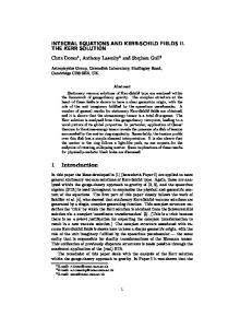
with p = parity (even or odd) of the vector products in S. Because both S −1 and S are factors in (9), the sign of S and (non-zero) scalar factors of S always cancel. We therefore equate operators S if they only differ by real scalar factors (including positive and negative signs)! 3. TWO-DIMENSIONAL POINT GROUPS Fundamental are the two-dimensional symmetries of regular polygons with n=1,2,3,4,6 corners.[4] (With n=5, no lattice can be built.) For an interactive online visualization see [8]. For n=1 there is no symmetry apart from the identity 1. For n=2 we have two points at x1=+a, and x2=− a. The two symmetry operations are the identity and the reflection at the plane perpendicular to a: x’= −a−1xa.
x’=baxab/a2/b2=b-1a-1xab=(ab)-1x(ab)=R-1xR(11) Compare Fig. 1.
(7)
etc. From elementary geometry we know that two reflections at planes with normal vectors c,d enclosing the angle θ/2 result in a rotation by angle θ. A general rotation operator (rotor) is therefore the product of two vectors R=cd enclosing half the angle of the final rotation. A sequence of three reflections at planes with normal vectors c,d,e gives a rotary-reflection: x’=(−1)(cde) −1x cde,
perpendicular (90˚=180˚/2) to a:
(10)
Instead of the reflection, we can also use a 180˚ rotation with the help of any vector b
Fig. 1. Regular polygons (n=2,3,4,6) with vectors a,b. For n=3 we have a regular triangle centered at the origin as in Fig. 1. We can take one vector a pointing to one corner and a vector b pointing to the middle of a side, so that the two enclose +60 ˚=180˚/3. The three symmetry rotations (120˚, 240˚, 360˚) in positive sense are: R=ab, R2=(ab)2, R3=(ab)3= −1.
(12)
The three symmetry reflections (6) are at the three lines through the center and the corners (different sign, because here a is in the line of reflection!): x’=a-1xa, x’=a-1R-1xRa, x’=a-1R-2xR2a.
(12a)
For n=4 we have a square centered at the origin (Fig. 1.) We can take one vector a pointing to one corner and a vector b pointing to the middle of a side, so that the two enclose +45˚=180˚/4. The four symmetry rotations (90 ˚ ,180 ˚ ,270 ˚,360˚) in positive sense are: R=ab,R2=(ab)2,R3=(ab)3,R4=(ab)4= −1. (13) The four symmetry reflections (6) are at lines perpendicular to vectors a, b, R-1aR, R-1bR. For n=6 we have a regular hexagon centered at the origin as in Fig. 1. We can take one vector a pointing to one corner and a vector b pointing to the middle of a side, so that the two enclose +30 ˚ =180 ˚ /6. The six symmetry rotations (60,120,180,240,300,360˚) in positive sense are: R=ab, R2, R3, R4 ,R5, and R6= −1.
(13a)
The six symmetry reflections (6) are at lines perpendicular to vectors a,b,aR2,bR2,aR4,bR4. In general the point symmetry group of a regular polygon with n corners is generated by a vector
a pointing to a corner and a vector b to the middle of an adjacent side, such that a,b enclose +180˚/n. (Rn = −1 is equivalent to this.) Using R=ba, instead of R=ab would generate rotations of opposite sense.
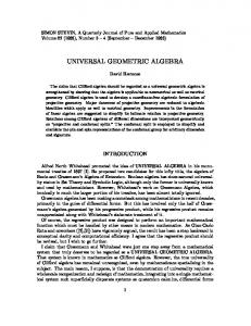
edge vectors a,b,c of unequal length. We now get the three symmetry groups: 2 2=V={ab,bc,ac,1}, 2=C2v={a,b,ab,1}, 22=Vh={a,b,c,ab,bc,ac,abc,1}.
(16) (17)
4. THREE- DIMENSIONAL POINT GROUPS All known three-dimensional crystal lattices can be characterized by their crystal cells shown in Figs. 2,3 and 4. The symmetry transformations of these cells, which leave the center points O invariant, form groups of symmetry operations, called point groups. Altogether there are 32 point groups associated with seven crystal classes.[4,5,6]
Fig. 2. Triclinic, monoclinic and orthorhombic crystal cells with invariant point centers O. The triclinic cell of Fig. 2 has three sides of unequal lengths and 3 unequal non-orthogonal angles. The only two symmetry operations are inversion i and identity 1, giving the groups: 22=Ci={i=a’b’c’, 1},
1=C1={1},
(14)
The left group symbol 22 was introduced in [4], meaning that 3 orthogonal vectors a’b’c’ (with angles 180˚/2) are multiplied to give i. For using the non-orthogonal edge vectors a,b,c, we need to replace i=a∧b∧c in (14). [4] uses overbars instead of underlines. The second symbol is the Shoenflies symbol. The monoclinic cell of Fig. 2 has edge vectors a,b,c of unequal length. Only the angle between a and b is not 90˚. We have the following three groups: 2=C2={R=a∧b,1}, 1=CS={c,1}, 22=C2h={c, R, cR, 1},
(15) (15a)
where cR is a rotary-reflection. In (14)-(15a) the generators are shaded. The orthorhombic cell of Fig. 2 has orthogonal
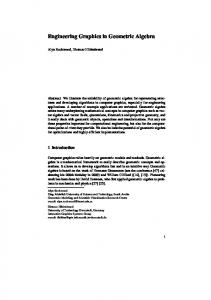
Fig. 3. Tetragonal cell, trigonal (|a’|=|b’|=|c’|) cell (side view and top view along d-axis A’OA). a*, a, b, b* all in paper plane perpendicular to d, containing O. In the tetragonal cell of Fig. 3 two of the orthogonal edge vectors a,b’,c have equal length (|a|=|b’|). We gain a 4-fold rotation symmetry around the c-axis. To generate the symmetry groups we choose a vector b=(a+b’)/2 pointing to a corner of the a,b’-square. The angle of a and b will therefore be 45˚=180˚/4. Defining the 90˚ rotation generator R = ab,
(18)
the symmetry groups obtained are now: 4=C4={R, R2, R3, R4 = 1}, (18a) 42=S4={abc=Rc, (Rc)2=R2, (Rc)3=R3c, (Rc)4=1} (19) 42=C4h={R,R2,R3,1, c,Rc,R2c,(Rc)3=R3c}, (20) 4 2=D4={R,R2,R3,1, bc,Rbc,R2bc,R3bc}, (21) 4=C4v={a, b, aR2, bR2, R, R2, R3, 1}, (22) 42=Vd={a,bc,abc=Rc,(Rc)2=R2,R3c, aR2=bab, a(Rc)3=bR2c,1}, (23) 42=D4h={a, b, aR2, bR2, c, R, R2, R3, 1, bc, ac, aR2c, bR2c, Rc, R2c=i, R3c}. (24) The highest order group 42 of (24) is called the holohedry of the tetragonal cell containing all other groups (18a)-(23) as subgroups. (24) lists line by line: five reflections, four rotations (90,180,170,360 ˚ ), four 180 ˚ rotations and three rotary-reflections, with R2c equal the inversion. In (18a)-(24) some algebraic identities are inserted, in order to ease the recognition of
the subgroup relationships. The trigonal (rhombohedral) cell of Fig. 3, can be visualized as a cube stretched along one space diagonal AA’. The three originally orthogonal edge vectors a’,b’,c’, emanating at A, will end up with mutually equal angles less than 90˚. We call the AA’ axis vector d= a’+b’+c’. We further define vectors a=b’×d, b=d×(d× c’)=(d∧c’)d, with angle 30˚=180˚/6 and an alternative vector pair a*=aba, b*=bab also with angle 30 ˚ . (Compare Fig. 3) Defining the rotary-reflection Rr = abd = a*b*d,
(25)
the highest order symmetry group (holohedry) of the trigonal cell is: 62=D3d={a, aRr2, aRr4, bd, Rr2bd, Rr4bd, Rr, Rr3=i, Rr5=(ab)5d, Rr2=(ab)2, Rr4=(ab)4, 1}.
(26)
(26) lists line by line: three reflections, three 180 ˚ rotations, three rotary-reflections (the second equals the inversion), and three rotations (120,240,360˚). 62=D3d has the following four subgroups: 62=C3i={Rr, Rr2, Rr3=i, Rr4, Rr5, 1}, 3 2=D3={R=a*b=(ab)2, R2, R3=−1, bd, Rbd=a*d, R2bd=a*ba*d}, 3= C3v ={a, b*, aR2, R, R2, R3}, 3= C6 = {R, R2, R3}.
(27) (28) (29) (30)
(32)
The holohedry 62 of (32) contains line by line: six reflections, six rotations (60,120,180,240,300, 360 ˚ ), six rotary-reflections, and six 180 ˚ rotations. The hexagonal holohedry 62 has the following six subgroups: 62=C6h={R, R2, R3, R4, R5, 1, c, cR, cR2, cR3, cR4, cR5}, 6 2=D6={R, R2, R3, R4, R5, 1, bc, Rbc, R2bc, R3bc, R4bc, R5bc} 6=C6v={R, R2, R3, R4, R5, 1, a, b, aR2, bR2, aR4, bR4}, 6=C3={R, R2, R3, R4 ,R5, 1}, 32=D3h={a, b*=bR=aR2, aR4=b*R2=b*ab*, R2,R4,1,c,R2c,R4c,ac,b*c=acR2,acR4}, 32=C3h={R2=ab*, R4, 1, c, R2c, R4c}.
(33) (34) (35) (36) (37) (38)
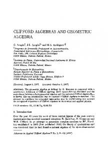
For the group 6 2 it is interesting to note that: Rbc=ac, R2bc=bcR4, R3bc=R2ac=acR4, R4bc=bcR2, R5bc=R4ac=acR2. (39) For the cubic crystal cell of Fig. 4 we define the three vectors a,b,c, such that a points to the middle of a side square face, b and c point to the middle of two edges, and the angles are 45˚ between a and b, 60˚ between b and c, and 90˚ between between c and a. We further define another edge middle vector a*=abcba. a*,b,c all have mutual angles of 60˚. The cubic holohedry has 48 elements: 43=Oh={a,b,c,bab,cbabc,(ab)2c(ba)2,cbc,a*,aba, i=(ab)2cbabc, 1, ab, (ab)2, (ab)3, babc, (babc)2, (babc)3, a*a, (a*a)2, (a*a)3, (ab)2c(ba)2a, cbabcaba, abcb,ac,babcbc,bcbabc, cbcaba, abacbc, (a*b)2, a*b, acba, abca,bc,(bc)2, abi, (ab)3i, babci, (babc)3i, a*ai, (a*a)3i, cbcabai, abacbci, (a*b)2i, a*bi, acbai, abcai, bci, (bc)2i}. (40)
Fig. 4. Hexagonal and cubic cells. For the hexagonal cell we define like in Fig. 4 two vectors a and b (at 30˚=180˚/6 angle) and for convenience an extra vector b*=bab (at 60˚ angle to a). The vertical vector is c. The holohedry is now with R=ab, Rc=cR, R2=ab* 62=D6h={a, b,aR2, bR2, aR4, bR4, R, R2, R3, R4, R5, 1,
c, cR, cR2, cR3=i, cR4, cR5, ac, bc, acR2, bcR2, acR4, bcR4}.
(31)
The 1st line of (40) are 9 reflections, the 2nd line the inversion and identity, the 3rd and 4th line three triples of rotations by (90,180,270˚), the 5th line six 180˚ rotations, the 6th line four pairs of rotations by (120,240˚) around the four space diagonals, the 7th line three pairs of rotary-inversions, and the 8th and 9th line four pairs of rotary-inversions around the four space diagonals. The cubic holohedry 43 of (40) has the
following subgroups: 43=Th={a, bab, cbabc, i, 1, (ab)2, (babc)2,(a*a)2, cbcaba, abacbc, (a*b)2, a*b, acba, abca,bc,(bc)2, cbcabai ,abacbci, (a*b)2i, a*bi, acbai, abcai, bci, (bc)2i}, (41) 4 3=O={ab, (ab)2, (ab)3, babc, (babc)2, (babc)3, a*a, (a*a)2, (a*a)3, 1, (ab)2c(ba)2a, cbabcaba, abcb,ac,babcbc,bcbabc, cbcaba,abacbc,(a*b)2,a*b,acba,abca,bc,(bc)2}, (42) 33=Td={b, c, (ab)2c(ba)2, cbc, a*, aba, 1, (ab)2, (babc)2, (a*a)2, cbcaba, abacbc, (a*b)2, a*b, acba, abca,bc,(bc)2, abi, (ab)3i, babci, (babc)3i, a*ai, (a*a)3i}, (43) 3 3=T={1,(ab)2,(babc)2,(a*a)2, cbcaba,abacbc,(a*b)2,a*b,acba,abca,bc,(bc)2}. (44) 5. VISUALIZATION OF CRYSTAL CELL SYMMETRIES A visualization of the various point symmetry groups can further their understanding considerably. For this purpose we employed the freely available software CLUCalc [7]. CLUCalc is a 3D-visualization tool with an extensive scripting language, which also supports Geometric Algebra. The script that was developed is also available from [7]. In the following a short introduction to the usage of the script is given. When CLUCalc starts up, it opens three windows: a script window, a text output window and a visualization window (Fig. 5). Through the menu of the script window the script can be loaded. After the point symmetry group script has been loaded, the visualization window is split into three areas: at the left a descriptive text containing interactive links is given, at the bottom control elements are shown and in the remaining space the crystal cell and related elements are visualized. The visualization is best viewed when the visualization window is maximized. Initially the two crystal cells with a triclinic symmetry are shown. By clicking on the blue text links in the left area with the mouse pointer, one can switch to crystal cells with different symmetries. The left crystal cell is always the initial cell, while the right cell shows the
transformed crystal cell. The transformations performed are shown above the crystal cells. Initially only a ‘1’ is shown, i.e. the identity transformation. In order to perform group transformations on a cell, one first has to select a group by clicking on one of the blue group identifiers. Then the group generators become active, i.e. they become blue links. Clicking on one of the group generators applies the corresponding transformation to the left crystal cell, and the result is shown by the right cell. If a sequence of group generators are selected, one after another, the right cell represents the total transformation. The history of transformations is shown above the cells. As soon as more than one generator has been applied, a number of control elements become available at the bottom of the visualization window. The control entitled ‘Generator Position’ is a slider, which allows one to step through the series of operations performed on the initial cell. Furthermore, a set of buttons appear which can be used to reset the list of generators, or to remove single generators. The total transformation operator is also visualized in the initial cell. In order to rotate the visualization for inspection, one has to place the mouse pointer somewhere in the visualization area, hold down the left mouse button and move the mouse. To achieve a translation, the same has to be done with the right mouse button. Furthermore, the current group generators are visualized in a sub-window of the visualization area. In order to rotate this visualization, one first has to select ‘mouse mode 1’, which can be done through the menu. Then the left mouse button has to be held down while moving the mouse. Note that for each type of crystal cell, a (pseudo-) group denoted with a question mark is available. Selecting this group, gives access to a set of operators, that by themselves may not represent symmetry operations. However, combinations of these may again represent symmetry operations. This functionality was added to also show which transformations do not belong to the symmetry groups of a particular crystal cell. 7. CONCLUSIONS Though the underlying geometric ideas are contained in [4], the present work is the first paper treating all elements of all 32 point groups
Fig. 5. Example view of point symmetry group visualization script. of three dimensional crystal cells explicitly. The explicit representation of all point symmetry group elements as a geometric product of physical vectors taken from the crystal cell is also intended to serve as a reference for future research. The interactive visualization software tool will be a valuable teaching resource for both instruction and self-study. In the future we intend to apply an analogous geometric and explicit approach to the 17 two dimensional space groups (wallpaper groups) and subsequently to the full set of 230 crystallographic space groups. This research will also be accompanied by the creation of corresponding visualization software. After the completion of these basic geometric formulations, we hope to show how this geometric approach leads to new insights for the analysis of crystal symmetry structures by physical methods, like diffraction patterns, etc. ACKNOWLEDGEMENTS E. Hitzer wants to thank God for his creation: “It is I who made the earth and created mankind upon it. My own hands stretched out the heavens; I marshaled their starry hosts.”[9] He further wants to thank his family for their patient
support and the Cognitive Systems group of the University of Kiel for their hospitality when doing this research. REFERENCES 1. N.W. Ashcroft, N.D. Mermin, Solid State Physics, Sounders College, Philadelphia, 1988. 2.D. Hestenes, New Foundations for Classical Mechanics, Kluwer Academic Publishers, Dordrecht, 1999. 3. D. Hestenes, G. Sobczyk, Clifford Algebra to Geometric Calculus, Kluwer, Dordrecht, 1984. 4. D. Hestenes, Point Groups and Space Groups in Geometric Algebra in L. Dorst, C. Doran, J. Lasenby (eds.), Applications of Geometric Algebra in Computer Science and Engineering, Birkhaeuser, Boston, 2002, pp. 3-34. 5. J.D. M. Gutierrez, Operaciones de simitria mediante algebra geometrica aplicadas a grupos cristalograficos, Tesis, UNAM, Mexico 1996. 6. Th. Hahn, Int. Tables for Crystallography, Volume A: Space-group symmetry, Kluwer, Dordrecht, 1992. 7. http://www.clucalc.info/ 8. http://sinai.mech.fukui-u.ac.jp/gcj/software/ GAcindy-1.4/GAcindy.htm 9. Bible, Isaiah 45:12 (NIV).