JOURNAL OF APPLIED PHYSICS
VOLUME 90, NUMBER 6
15 SEPTEMBER 2001
Defect modes in coaxial photonic crystals Garrett J. Schneider, Stefan Hanna,a) Joshua L. Davis,b) and George H. Watsonc) Department of Physics and Astronomy, University of Delaware, Newark, Delaware 19716
共Received 16 April 2001; accepted for publication 8 June 2001兲 One-dimensional 共1D兲 photonic crystals have been constructed by connecting segments of coaxial cable of differing characteristic impedance. Impurities have been introduced into these crystals by inserting cable segments to break the crystal symmetry. This system provides a simple way to study 1D photonic band structure effects with complete control over impurities in the lattice. We have studied the effects of the size, number, and location of defects in the lattice. We have also measured directly the concentration of energy in the steady-state electromagnetic fields within doped crystals, and observed the influence of the defects on the phase 共dispersion兲. A modified dielectric stack model was developed to describe this system, with the results in excellent agreement with our measurements. Our findings compare favorably to previously published measurements of transmission and phase change in three-dimensional photonic crystals. © 2001 American Institute of Physics. 关DOI: 10.1063/1.1391220兴 I. INTRODUCTION
arrangement of the defect sites relative to each other. Thus it was not possible to isolate a particular configuration with a well defined defect position within the face centered-cubic 共fcc兲 unit cell, nor to arrange the defects in any particular way throughout the crystal. We have also recently reported the results of a study using a ‘‘quasi one-dimensional 共1D兲’’ system which overcomes the limitations of the colloidal crystals when studying defects: the coaxial connector photonic crystal, assembled from a periodically arranged series of ‘‘tee’’ and ‘‘barrel’’ microwave coaxial connectors.11 That system exhibited photonic band structure arising from the ‘‘Bragg-like’’ reflections from the open ends of the tee connectors 关satisfying a 1D Bragg condition: 2a ˜ ⫽m, where ˜a is a characteristic length,11 ⫽c( 冑⑀ ) ⫺1 the wavelength, and m an integer兴. Impurities were introduced by altering the length, spacing, and/or termination of the open ends. The microwave connector system suffered from numerous shortcomings which limited our ability to thoroughly explore the effects of defects. First, the quasi-1D nature prevents any true 1D model from accurately describing this system. Second, due to the size of the connectors (ⱗ10 cm), the band structure effects appeared in the GHz range, which required measurement techniques based on the power dissipated in a resistive load placed at the crystal’s far end with a continuous input signal. This technique precluded any phase measurements or measurements of the field distribution within the crystal because of loading effects. Third, only a small number of discrete types of defects were introduced, and these defects were not well characterized in terms of their effect on the amplitude and phase of the reflections they generated. A different photonic system was constructed for this study from standard coaxial cables, which alleviates the shortcomings of the microwave connector system. These crystals were constructed from alternating segments of RG58/U 共52 ⍀兲 and RG-59/U 共75 ⍀兲 type cable. The segments used were 10–30 m long, yielding stop bands in the frequency range of ⬃1 – 10 MHz. This frequency range permits
A periodic dielectric medium can have a profound effect on electromagnetic waves that propagate through it. If the crystal structure and dielectric contrast are sufficient, such a medium, called a photonic crystal, forbids photon propagation for certain bands of frequencies irrespective of the polarization or propagation direction, leading to a complete photonic band gap.1,2 Such a structure is projected to have a significant impact on a wide range of photonic applications.3,4 Applications of photonic crystals will be enhanced by ‘‘doping’’ them with defects/impurities to generate defect/impurity states within the band gap.5–7 Impurity effects have been observed to be extremely sensitive to the configuration of the impurities in their respective unit cells, as seen in previous studies in which the donor impurity levels split into two upon displacement of the donor impurity relative to its lattice site.7 As the impurities begin to approach a characteristic length of each other, these effects are also determined by the relative positions of neighboring impurity sites; impurity modes were found to be dependent on whether the defects appeared on neighboring lattice sites or were separated by a lattice site.8 In previous work we reported on impurity effects in polystyrene colloidal photonic crystals.9,10 Dopants of a different particle size or material were substitutionally introduced into a host matrix of polystyrene microspheres, resulting in the appearance of broad impurity states within the stop band. Due to small deviations in the size of the host and dopant polystyrene microspheres, the impurity effects in doped colloidal crystals represent an average over various defect configurations that are slightly displaced from their mean position in the unit cell. Moreover, as colloidal crystals are self-assembling systems, there was no control over the a兲
Present address: Physikalisches Institut, Universita¨t of Bayreuth, Bayreuth, Germany. b兲 Present address: Department of Physics, University of Michigan, Ann Arbor, MI 48109. c兲 Corresponding author; electronic mail:
[email protected] 0021-8979/2001/90(6)/2642/8/$18.00
2642
© 2001 American Institute of Physics
Downloaded 03 Jul 2002 to 128.175.122.127. Redistribution subject to AIP license or copyright, see http://ojps.aip.org/japo/japcr.jsp
Schneider et al.
J. Appl. Phys., Vol. 90, No. 6, 15 September 2001
more thorough characterization and a larger variety of measurements because the time-varying field can be observed directly. Also, the cable system is truly one dimensional, since it lacks the tee structures that split electromagnetic waves along multiple paths. Because it is truly 1D, quantitative analytical modeling of the cable system is much easier than for the quasi-1D connector system. 共We note that Vasseur, et al. have published a method based on interface response theory for modeling structures similar to the coaxial connector system with defects, along with experimental results obtained using coaxial cables.12 Because their model requires the relevant lengths of the waveguide to be much larger than the waveguide diameter, it is not clear whether it could be applied to the microwave coaxial connector system.兲 Finally, because coaxial cables can be cut to an arbitrary length, we were able to vary continuously the relative ‘‘strength’’ of impurities. II. EXPERIMENTAL DETAILS
The coaxial cable crystals that served as a basis for this study consisted of 10 unit cells. Each unit cell was comprised of a segment of RG-58/U coaxial cable 共characteristic impedance Z 0 ⫽52 ⍀兲 followed by a segment of RG-59/U (Z 0 ⫽75 ⍀) cable; both types of cable were filled with polyethylene ( ⑀ ⬇2.3⑀ 0 ), corresponding to a nominal propagation speed of 0.66c. Segments of coaxial cable were connected by standard BNC connectors. Impurities of various strengths were incorporated by substituting segments of different lengths at selected positions in the lattice. Initial measurements were obtained with a continuous 共cw兲 technique, in which sinusoidal signals were generated by a Stanford Research Systems DS340 synthesized function generator over the frequency range of 1–15 MHz. The signal amplitudes were measured at the output of the crystal and at interfaces between cables using a Tektronix TDS 520 twochannel digitizing oscilloscope. The oscilloscope was also used to measure the relative phase between the signals at the two channels. The output impedance of the function generator was 50 ⍀, while the input impedance of the oscilloscope channels was set at either 1 M⍀ or 50 ⍀, based on whether a channel was probing within the crystal or at the output end, respectively. Several problems arose with the cw technique. First, the measurements, although automated by computer, were very slow. Second, the phase measurements reported by the TDS 520 were noisy and inconsistent, particularly within stop bands in which the amplitude was small. Third, we found that the function generator suffered from loading effects that caused its output amplitude to change slightly as the frequency was tuned, in a way that was not exactly reproducible between scans, possibly because of the fact that the effective load changed whenever the crystal configuration was modified. This made normalizing to the input inconsistent and introduced errors into the data. Later we switched to a pulsed technique, which yielded the same results much faster without the aforementioned errors. In the pulsed technique, the signal source was a Hewlett-Packard 8003A pulse generator, which was used to produce 40 ns rectangular pulses at a repetition rate of ⬃10 kHz. The pulse width corresponds to a
2643
frequency bandwidth of 15 MHz 关full width at half maximum 共FWHM兲兴. Pulses were sent through the crystal, and the TDS 520 was used to acquire the output wave forms, to which a complex fast Fourier transform 共FFT兲 was applied. Transmission and phase information was then obtained from, respectively, the magnitude and argument of the complex FFT data normalized by the FFT of the input pulse. Because the pulse propagation time through the crystal was much longer than the pulse width, the pulsed method was immune to the effects of changing the effective load. In both techniques, the collection of data was controlled by a computer using software written in LabView.13 An analytical model was developed to describe the coaxial cable system. It is based upon a dielectric stack, modified to account for two important differences in the cable system: 共1兲 at the frequencies used in the study, the cables are lossy 共and consequently dispersive兲, and 共2兲 the reflection and transmission coefficients at the cable interfaces are determined by the mismatch in characteristic impedance, while the propagation speed is determined by the dielectric properties of the filler material. The model allows the physical parameters 共length, impedance, permittivity, attenuation兲 of each layer to be specified individually, permitting us to examine the effects of an arbitrary number and type of impurities. These parameters were provided by the manufacturer of the cables,14 with the exception of length, which we measured directly. Hence, there are no adjustable parameters in the model that affect the photonic structure properties 共e.g., the frequencies of stop bands and impurity modes兲. The only fits performed in the modeling process were one-time leastsquares fits to the manufacturer-provided attenuation data to best estimate the absorption as a function of frequency; after this initial step no fitting of any kind was done when generating results from the model. A detailed description of the model may be found in the Appendix. In addition, 1D finitedifference time-domain 共FDTD兲 computations were performed to model the field amplitudes at points within the crystal, rather than merely at the output end. 共This information can also be obtained analytically using the method of characteristic matrices.15兲 III. DISCUSSION OF THE RESULTS A. Pure and doped crystals
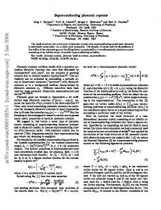
Figure 1 depicts two transmission scans from undoped crystals. Figure 1共a兲 shows the spectrum of a crystal consisting of 10 unit cells, each cell comprised of a 20 m segment of 52 ⍀ cable and a 15 m segment of 75 ⍀ cable. Multiple stop bands of varying depth can be seen over this frequency range at frequencies satisfying the 1D Bragg condition. Figure 1共b兲 is the spectrum of a slightly different, more symmetric crystal in which all cable segments were 15 m long. The greater symmetry in the crystal structure results in a simpler, more symmetric transmission spectrum. It is also apparent in Fig. 1 that the cables are lossy in this frequency range, and that the attenuation increases with increasing frequency. We were able to account for this in our model by choosing a suitable frequency-dependent absorption ␣ ( ) based on the manufacturer’s attenuation specifications.
Downloaded 03 Jul 2002 to 128.175.122.127. Redistribution subject to AIP license or copyright, see http://ojps.aip.org/japo/japcr.jsp
2644
J. Appl. Phys., Vol. 90, No. 6, 15 September 2001
Schneider et al.
FIG. 2. Transmission spectra of doped and undoped coaxial cable crystals. The doped crystal was identical to that described in Fig. 1共b兲 with the exception that in 2 of the 10 unit cells the 52 ⍀ segments were 20 m long. The open circles are measured data, the solid curve is from the analytical model, while the dotted curve is from the model for an undoped crystal, shown to highlight the changes caused by the presence of the impurities.
FIG. 1. Transmission spectra for coaxial photonic crystals consisting of 10 unit cells of alternating 52 and 75 ⍀ coaxial cable segments. In 共a兲, the 52 ⍀ segments were 20 m long and the 75 ⍀ cables were 15 m long. In 共b兲, all segments were 15 m long. The open circles are measured data; the solid curves are the results from the analytical model described in the Appendix.
Also shown in Fig. 1 are the results from the model described in the Appendix. The model is seen to be in good agreement with our measurements, for both the position and depth of stop bands, as well as for the attenuation. The small discrepancies between the model and the data are consistent with minor variations (⬃1%) in the lengths of the cable segments and the cable impedances. Figure 2 shows the spectrum obtained from a doped coaxial crystal. The crystal was identical to that used to obtain Fig. 1共b兲, except that in 2 of the 10 unit cells 共cells 4 and 7, from the source end兲, the length of the 52 ⍀ segments was increased from 15 to 20 m. The undoped spectrum from Fig. 1共b兲 is also included to highlight the changes caused by the presence of the defect cells. Note the strong impurity mode in the center of the stop band at 9.8 MHz and the mode at the edge of the first stop band at 3.8 MHz. Also apparent in Fig. 2 is widening of the stop bands compared to those in the undoped crystal spectrum. Note that, while the first band at 3 MHz may at first appear narrowed, this is an illusion caused by the proximity of the impurity mode to the band edge; the band is seen to be wider near the top. Further examples and discussion of band widening may be found in Sec. III B. B. Varying the number and location of defects
Figure 3 summarizes the effects of changing the number and position of impurities. The results depicted here all
qualitatively replicate those obtained using the microwave coaxial connector system and discussed in detail in a previous paper.11 We have included them here to demonstrate the behavioral similarity between the cable and connector systems, and to emphasize that, while the cable system has many advantages over the connector system, as discussed earlier, it does not sacrifice any key photonic properties. Figure 3共a兲 illustrates the effect of moving a single defect within a crystal. The crystal used in Fig. 3共a兲 had 10 unit cells, each unit cell a 20 m/52 ⍀ segment and a 15 m/75 ⍀ segment. A single defect was introduced into various unit cells by replacing the 20 m/52 ⍀ segment with a 3 m segment as indicated in the legend of Fig. 3共a兲. The plots illustrate how the impurity mode is ‘‘absorbed’’ by the crystal surface, gradually weakening and ultimately disappearing as the defect location moves toward the end of the crystal. Figure 3共b兲 shows how the impurity mode grows stronger with increasing number of defects. The data shown in Fig. 3共b兲 came from a 20 cell, 20 m/52 ⍀–15 m/75 ⍀ crystal with the number of defects indicated in the legend. All the defects were identical, 2 m/52 ⍀ segments replacing the 20 m segments. In introducing the defects, care was taken to avoid the surface effects discussed above as well as the interaction effects illustrated in Fig. 3共c兲 and discussed below. Figure 3共c兲 shows how multiple, identical defects interact when the separation between them decreases. This crystal was again a 10 cell, 20 m/52 ⍀–15 m/75 ⍀ based system, with two identical 30 m/52 ⍀ defects introduced in positions separated by a varying number of unit cells as indicated in the legend. When the defects are well separated, a strong, single peak results. However, when the separation is fewer than four unit cells, the impurity mode is observed to split into multiple distinct peaks. It should be noted that all the results depicted in Fig. 3 were obtained from the analytical model. Corresponding measurements were made, with agreement between the
Downloaded 03 Jul 2002 to 128.175.122.127. Redistribution subject to AIP license or copyright, see http://ojps.aip.org/japo/japcr.jsp
J. Appl. Phys., Vol. 90, No. 6, 15 September 2001
Schneider et al.
2645
FIG. 4. Continuous variation of impurity mode frequency with the length of a single defect segment. 共a兲 Stop-band spectra from a 10 cell crystal with a defect of the length indicated in the legend. The defect was in cell 5 for all scans. 共b兲 Contour plot indicating the results from the model applied to the same crystal, but varying the defect length over a much larger range. Horizontal sections of the contour plot correspond to transmission spectra like those in 共a兲. The dotted line traces the motion of the impurity peak across the stop band.
FIG. 3. 共a兲 ‘‘Absorption’’ of the impurity mode by the crystal surface. These transmission spectra were obtained by modeling a 10 cell crystal with a defect in the cell shown in the legend. As the defect cell approaches the end of the crystal, the impurity peak weakens and eventually disappears. 共b兲 Increasing impurity peak height with the number of defects. Spectra were obtained by modeling a 20 cell crystal with the number of defects indicated. 共c兲 Interaction of multiple defects. As two identical defects are brought closer together, the impurity mode widens and splits into two distinct peaks. The spectra were obtained by modeling a 10 cell crystal with two defects separated by the number of unit cells indicated.
model and the data comparable to that seen in Figs. 1 and 2, but are not shown to avoid cluttering the figures. Significant band widening can be seen in all the plots of Fig. 3. In previous studies of a variety of photonic crystal systems, both experimental and theoretical, we have observed band widening in the presence of impurities in our systems.9,11 In these past studies, we observed asymmetric band widening, where the high-frequency band edge remains fixed while the low-frequency edge shifts toward a lower
frequency. It is apparent from Fig. 3 that, for these coaxial cable photonic crystals, the band widening is more symmetric. The critical difference between this system and those studied previously regarding the different band-widening behavior is not yet understood. C. Continuous variation of impurity strength
One of the opportunities afforded by the coaxial cable system is the ability to study the effect of continuously varying the ‘‘strength’’ of a defect. Studies of photonic systems have shown that changing the optical volume of a defect causes a shift in the position of the defect mode within the stop band.7,16 The exact dependence of the defect mode frequency on defect volume varies based on the dimensions of the system, and whether the defect is a ‘‘donor’’ or ‘‘acceptor’’ type. Hence, we expected to see gradual movement of the peak as we varied the defect length, and indeed this is what we found from both our measurements and the model; the results are shown in Fig. 4. Repeated scans of a crystal with a single defect were collected, with the length of the
Downloaded 03 Jul 2002 to 128.175.122.127. Redistribution subject to AIP license or copyright, see http://ojps.aip.org/japo/japcr.jsp
2646
J. Appl. Phys., Vol. 90, No. 6, 15 September 2001
defect segment cut back 1 m after each scan. An incremental shift in the position of the impurity mode was observed with each cut-back step. Figure 4共a兲 shows several transmission scans across a stop band with an impurity peak. The movement of the impurity mode from the middle of the stop band toward lower frequencies as the defect length increases is striking. The data in Fig. 4共a兲 were obtained from a crystal consisting of 10 unit cells, each unit cell comprised of a 20 m/52 ⍀ segment and a 15 m/75 ⍀ segment. The defect was in the 75 ⍀ segment in unit cell 5. Note that when the ‘‘defect length’’ is 15 m, this is in fact no defect at all and, as expected, there is no mode within the stop band. Figure 4共b兲 shows the results of using the model to simulate cutting back the defect segment length from 70 m down to 0. In this contour map, horizontal slices correspond to transmission scans like those in Fig. 4共a兲. Several features in Fig. 4共b兲 are noteworthy. First, the frequency of the impurity mode changes continuously and approximately linearly with the defect length, as indicated in Fig. 4共b兲 by the dashed line that traces the peak across the stop band. Second, the motion is periodic in the defect length. The impurity mode starts near the middle of the band for a 0 m defect, moves to the left until it vanishes at 15 m, then reappears at the right side of the band edge. The period of the movement is simply the unit cell length. This is most clearly seen by examining the two lengths where there is no impurity mode at all, 15 and 50 m. The difference is the unit cell length, 35 m. The minimum at 50 m is deeper than at 15 m because of the additional absorption in the longer defect segment. This periodicity is clearly unique to 1D systems, and the period of the movement is simply the unit cell length because the propagation speeds are the same for both cable types used. D. Steady-state energy distribution within a doped crystal
The combination of macroscopic feature sizes and one dimensionality of the coaxial cable system makes it possible to probe the field amplitude at positions within the crystal without perturbing the system significantly, and thereby to map out the distribution of energy in the steady-state electromagnetic fields. Of particular interest was the effect of defect sites and the local concentration of energy within a defect. It is expected that localized modes are created by defects in a photonic crystal, with the amplitude of such modes enhanced in the region of the defect.17 We have used the coaxial cable system to measure directly the amplitudes as a function of position and frequency in a doped photonic crystal. The crystal used was a 10 cell, 15 m/52 ⍀–15 m/75 ⍀ lattice with a single defect introduced in unit cell 5 by removing the 52 ⍀ segment. The amplitudes were measured along the entire length of the crystal at 3.75 m intervals. This was accomplished with minimal perturbation of the system by cutting one 15 m segment of each cable type into four pieces of equal length, creating points where the measurements were taken by inserting a BNC tee connector and connecting it directly to a high-impedance oscilloscope input. By substituting these ‘‘broken’’ segments for uncut segments of the same type one at a time, we were able to take measurements along the entire length of the crystal. The results are shown
Schneider et al.
FIG. 5. Spatial distribution of energy in the steady-state fields. 共a兲 Contour plot of the amplitude vs frequency and position. The crystal was a 10 cell, 15 m/52 ⍀–15 m/75 ⍀ lattice with a defect introduced cell 5 by removing the 52 ⍀ segment. There is enhancement (⬃6 dB) of the amplitude at the impurity mode frequency 共3.23 MHz兲 around the defect location 共120 m兲. 共b兲 Plot of amplitude vs position at the defect frequency 关along the dotted line in 共a兲兴. Open circles are crystal measurements, and the solid curve is the result of a FDTD calculation.
in Fig. 5. Figure 5共a兲 contains a contour map in which the amplitude is plotted versus position and frequency. The defect mode is located at 3.23 MHz 共indicated by the dashed line兲, and the defect itself is at a position of 120 m. The bright spot at ⫽3.23 MHz, x⫽120 m indicates that the amplitude is enhanced at this point by 6 dB. Figure 5共b兲 is a plot of the amplitude versus position at the defect mode frequency, i.e., the data points along the dashed line in Fig. 5共a兲, along with the results of a FDTD calculation. The agreement between the measurements and the calculation is excellent. Additional calculations for the same structure indicate that, in the absence of losses, enhancement of over 16 dB is expected. The enhancement of the field amplitude in and around defects in photonic crystals is an important effect which can be taken advantage of in photonic applications. For example, Nakatsuka and co-workers have observed enhancement of nonlinear optical effects and two-photon fluorescence in thin film samples that are sandwiched between 1D photonic crystal stacks.18 This arrangement effectively creates a single photonic crystal in which the sample is a defect layer.
Downloaded 03 Jul 2002 to 128.175.122.127. Redistribution subject to AIP license or copyright, see http://ojps.aip.org/japo/japcr.jsp
J. Appl. Phys., Vol. 90, No. 6, 15 September 2001
Schneider et al.
2647
FIG. 7. Application of the analytical model to optical materials and length scales. The main area of the plot shows the phase 共left axis, open circles兲 and transmission 共right axis, solid curve兲 results obtained from the model when applied to a stack of 85 unit cells, each cell comprised of a 173 nm polystyrene layer and a 127 nm water layer. Seven percent of the polystyrene layers were dopant layers 290 nm thick. The inset shows similar results obtained from optical measurements on a doped fcc polystyrene colloidal crystal 共see Ref. 10兲.
FIG. 6. Phase change across stop bands arising from the photonic crystal structure. In 共a兲 the phase change is shown across a stop band with no impurity mode. In 共b兲, an impurity mode is present, centered at 3.23 MHz. The linear phase change and dispersion arising from attenuation in the cables were subtracted from the raw phase data before plotting. Open circles are measured data and solid curves are from the model. Transmission spectra are indicated by dotted curves in both plots.
E. Phase measurements: Photonic dispersion in doped crystals
Measurements of the phase shift on transmission through a photonic crystal reveal how the photonic dispersion rela tion is modified by the periodicity of the medium. Since we are only interested in the phase shift arising from the periodicity in the structure, we have removed the linear phase change with frequency ⌬ 0 arising from the effective over2 /2, where ⌬ 0 all permittivity of the medium ( ⑀ eff⫽c2eff ⫽ effd and d is the total crystal length兲, by subtracting a straight line fit from the phase data. In addition, there is also dispersion arising from the frequency-dependent attenuation in the cables as predicted by the Kramers–Kronig dispersion relations 共see the Appendix兲; this contribution to the phase change was also removed from the data. The remaining phase shifts, along with results from the model, are shown in Fig. 6. Both Figs. 6共a兲 and 6共b兲 were obtained from a 10 cell crystal with unit cells consisting of a 15 m/52 ⍀ segment and a 15 m/75 ⍀ segment. There were no defects in the crystal in Fig. 6共a兲, while in Fig. 6共b兲 the crystal contained one defect: in cell 5, the 52 ⍀ segment was removed. In both plots, the phase change grows in opposite directions as a stop band is approached from either side. Transmission spectra for each
crystal are overlaid with the phase data to indicate the positions of the stop band and impurity mode. The influence of the impurity mode on the phase change is clearly apparent in Fig. 6共b兲 as an inversion of the slope within the impurity peak. F. Comparison with colloidal photonic crystals
Our primary motivation for the work presented here was to find a simple photonic system that can be easily assembled and modeled, while retaining the essential characteristics which have been found in our earlier studies of threedimensional 共3D兲 colloidal photonic crystals. The success of the analytical model in predicting results from the coaxial cable crystal measurements is convincing evidence that this system satisfies the first criterion. To demonstrate that the second is also satisfied, we have used the coaxial cable model with parameters similar to those of polystyrene colloidal crystals to compare with measurements made on actual impurity-doped colloidal crystals. Figure 7 shows the transmission spectrum and phase change obtained by modeling a dielectric stack consisting of 85 unit cells, where each unit cell is comprised of a 173 nm layer of polystyrene (n ⫽1.59) and a 127 nm layer of water (n⫽1.33). Impurity layers, 290 nm thick, replaced the polystyrene layers in 7% of the unit cells, chosen at random. The inset in Fig. 7 shows previously published results obtained from a polystyrene colloidal crystal.10 The crystal used for the inset was a fcc lattice of 173 nm polystyrene spheres in water, with 7% of the spheres replaced by 203 nm dopant spheres. Data were taken along the fcc 关111兴 direction. The correspondence between the location of features in the wavelength spectrum can be understood by considering the 共first order兲 Bragg wavelength, given by c ⫽2n ¯ d, where ¯n is the average refractive index of the medium, and d is the
Downloaded 03 Jul 2002 to 128.175.122.127. Redistribution subject to AIP license or copyright, see http://ojps.aip.org/japo/japcr.jsp
2648
Schneider et al.
J. Appl. Phys., Vol. 90, No. 6, 15 September 2001
period, i.e., the unit cell thickness in 1D or the spacing between adjacent 共111兲 planes in 3D. For the colloidal crystal used 共neglecting the presence of the dopant spheres兲, d 111 ⫽330 nm, ¯n ⫽1.35, and c ⫽890 nm. Therefore the 1D model parameters were chosen such that d⫽300 nm and ¯n ⫽1.48, yielding the same c . 共The actual stop band positions in the transmission spectra are shifted slightly by the presence of the defects.兲 The thickness of the defect layers in the model was chosen to be larger than the basis polystyrene layers in order to replicate the ‘‘donor’’ nature of the defect in the colloidal crystal. Additionally, some ‘‘noise’’ was added to the thicknesses of the layers in the model to replicate the effect of the ⬃3% coefficient of variation in the size of the colloidal polystyrene particles. The qualitative similarity between the optical-scale model results and the actual colloidal crystal measurements is striking, indicating that much of the behavior observed in 1D coaxial cable photonic crystals is general to photonic systems of higher dimension as well. IV. SUMMARY
Coaxial cable crystals have been shown to provide an easily realizable 1D photonic band gap system. They have significant advantages over the microwave coaxial connector crystals studied previously, including greater flexibility in terms of the types of measurements possible, easier incorporation of continuously variable defects, and the ability to be accurately described by a 1D analytical model. Upon the introduction of impurities, they exhibit behaviors similar to those seen in the microwave connector system and/or in 3D colloidal crystals. These behaviors include the appearance of impurity modes within stop bands and band widening, multiple defect interactions leading to splitting of impurity modes, and modification of the photon dispersion relation manifested by a phase change within stop bands. One characteristic which had not been observed in previously studied systems was the symmetric nature of the band widening, possibly attributable to the truly one-dimensional nature of the coaxial cable system. Several measurements were made that were not possible in our previously studied systems. We examined the effect of continuously varying the size and hence the ‘‘strength’’ of impurities. As expected, the impurity mode frequency was seen to vary continuously with the length of the impurity in crystals with a single defect. We were able to probe the field at points throughout the crystal without perturbing the propagating states, which enabled the direct measurement of the field amplitudes as a function of frequency and position within the lattice. We observed the expected enhancement of the steady-state field amplitude within the defect at the impurity mode frequency. We also measured the phase shift arising from the photonic structure, and observed how the phase change is altered by the presence of a defect mode. A model based on a lossy dielectric stack was developed to describe the coaxial cable system. This model accurately predicts the results of our measurements without any fitting to the experimental data, thereby providing a simple yet highly accurate physical explanation of our observations. To
demonstrate the generality of the observed behaviors with respect to dimensionality, we have used our model to qualitatively reproduce both the transmission spectrum and phase shift obtained from a doped polystyrene colloidal crystal. ACKNOWLEDGMENTS
The authors would like to thank Dr. Janusz Murakowski of the Department of Electrical and Computer Engineering at the University of Delaware for his assistance in developing their analytical model. This work was supported by the National Science Foundation under Grant No. DMR-9974353. APPENDIX: MODEL CALCULATION METHOD
Maxwell’s equations for linear, charge-free media impose boundary conditions on the components of the electric and magnetic fields normal and tangential to an interface. For an interface between medium A, characterized by a permittivity of ⑀ A and permeability A , and medium B characterized by ⑀ B and B , the conditions are
⑀ A E A⬜ ⫽ ⑀ B E B⬜ ,
共A1a兲
EA 储 ⫽EB 储 ,
共A1b兲
A H A⬜ ⫽ B H B⬜ ,
共A1c兲
HA 储 ⫽HB 储 ,
共A1d兲
where ⬜ 共储兲 indicates the component normal 共tangential兲 to the interface. For a plane electromagnetic wave normally incident upon such an interface, traveling from medium A into medium B, application of Eqs. 共A1兲 yields solutions for the amplitude reflection and transmission coefficients r AB and t AB , respectively,
B⫺ A , B⫹ A
共A2a兲
2B , B⫹ A
共A2b兲
r AB ⫽ t AB ⫽
where ⫽ 冑 / ⑀ is called the wave impedance of a medium. r and t are defined in the usual way in terms of the electric field amplitudes, r⫽ 兩 E r /E i 兩 , t⫽ 兩 E t /E i 兩 , where E r , E t , and E i are the reflected, transmitted, and incident amplitudes, respectively. Note that t⫽1⫹r. Equations 共A2兲 apply to bulk media, but can be generalized to coaxial cables by substitution of the cables’ characteristic impedances in place of A and B . We assume a basic structure consisting of alternating layers/segments of two types of media/cable, designated as type A and type B. The thicknesses/lengths of these layers/ segments are a (n) and b (n) , respectively, where n indicates the unit cell number. We further assume an input wave described by E 共 x 兲 ⫽E 0 e i( x⫹ ) ,
共A3兲
where E 0 is the amplitude and the phase. We are free to disregard the time-dependent part of E (⬃e i t ) because we
Downloaded 03 Jul 2002 to 128.175.122.127. Redistribution subject to AIP license or copyright, see http://ojps.aip.org/japo/japcr.jsp
Schneider et al.
J. Appl. Phys., Vol. 90, No. 6, 15 September 2001
seek only steady-state solutions. is the complex wave number, given by
⫽ 冑 0 ⑀ ⫹i 共 ␣ /2兲 .
共A4兲
The absorption coefficient ␣ is twice the imaginary part of since intensity is proportional to the square of the amplitude. Note that when ␣ ⫽0, reduces to the familiar k⫽2 n/, where n is the refractive index and is the vacuum wavelength. If the absorption coefficient has some frequency dependence, i.e., ␣ ⫽ ␣ ( ), it implies that the 共real兲 permittivity is also frequency dependent 共dispersive兲. This is a result of the Kramers–Kronig dispersion relations, which show that the real and imaginary parts of 兵 关 ⑀ ( ) 兴 / ⑀ 0 ⫺1 其 are Hilbert transforms of each other,19 R关 ⑀ r 共 0 兲 ⫺1 兴 ⫽
2 P
T关 ⑀ r 共 0 兲 ⫺1 兴 ⫽⫺
冕
2 P
T关 ⑀ r 共 兲 ⫺1 兴 d, 2 ⫺ 20
⬁
0
冕
⬁
0
共A5a兲
0 R关 ⑀ r 共 兲 ⫺1 兴 d , 共A5b兲 2 ⫺ 20
where ⑀ r ⫽ ⑀ ( )/ ⑀ 0 , R and T denote the real and imaginary parts, respectively, and P indicates the Cauchy principal value. For the coaxial cables used in this study, we determined ␣ ( ) by fitting a simple function to attenuation data provided by the cable manufacturer. From that we approximated the imaginary part of ⑀ as T关 ⑀ ( ) 兴 ⬇ 冑¯⑀ / 0 ␣ ( )/ ⑀ 0 , where ¯⑀ ⫽2.3⑀ 0 is the average permittivity. Equation 共A5a兲 was then used to calculate the resulting frequency-dependent correction to ⑀. Failing to make this correction leads to a small discrepancy in the phase; it does not significantly affect the results of the amplitude calculation. Our goal is to calculate the overall amplitude transmission coefficient and phase at the output of a coaxial photonic crystal for any given frequency. We will accomplish our goal by working backwards; we assume an output of unit amplitude and zero phase traveling to the right, then apply Eqs. 共A2兲 at each interface to find the incident and reflected fields that would yield the assumed output. Equations 共A3兲 and 共A4兲 are applied to propagate between interfaces. Because we are working backwards, it is convenient to number the unit cells in reverse, i.e., the last cell in an N-cell crystal is cell 1, the first cell is cell N. The output is indicated by cell 0. Hence the calculation proceeds iteratively from the output E A(0) ⫽1 to the input E A(N) and then takes the ratio of the R R output to the input, which due to the assumptions mentioned above is just the inverse of the input. In our notational convention, the field amplitude in each layer is specified at the output side as two-element column vector,
冉 冊 (n)
E X(n) ⫽
EX
R
(n) EX L
,
where X is the layer type 共A or B兲, n is the unit cell number, and R(L) indicates the part of the field that is traveling to the right 共left兲. With these conventions, the calculation can be summarized as
冉兿
冊
N
E A(N) ⫽ where
( j) ⫽ M BA
and ( j) ⫽ M AB
j⫽1
冉 冉
共A6兲
( j) ( j⫺1) M AB M BA E A(0) ,
( j) ( j) a
⫺1 ⫺i A t BA e
( j) ( j) a
⫺1 ⫺i A r BA t BA e
( j) ( j) b
⫺1 ⫺i B t AB e
( j) ( j) b
⫺1 ⫺i B r AB t AB e
2649
( j) ( j) a
⫺1 i A r BA t BA e
( j) ( j) a
⫺1 i A t BA e
( j) ( j) b
⫺1 i B r AB t AB e
( j) ( j) b
⫺1 i B t AB e
冊 冊
,
共A7兲
.
共A8兲
Successive factors in the matrix product in Eq. 共A6兲 operate on the left side. Using Eq. 共A6兲 with the initial conditions E A(0) ⬅( 10 ) and a (0) ⫽0, we can compute the overall amplitude transmission coefficient T for an N-cell crystal by T⫽ 兩 共 E A(N) 兲 ⫺1 兩 , R
共A9兲
and the phase ⌽ of the output relative to the input by ⌽⫽⫺arg关共 E A(N) 兲 ⫺1 兴 . R
共A10兲
1
See, for example, special review issues, C. M. Bowden, J. P. Dowling, and H. O. Everitt, J. Opt. Soc. Am. B 10, 1 共1993兲; G. Kurizki and J. W. Haus, J. Mod. Opt. 41, 1 共1994兲. 2 Photonic Band Gap Materials, edited by C. M. Soukoulis 共Kluwer Academic, Dordrecht, 1996兲. 3 T. F. Krauss and R. M. De La Rue, Prog. Quantum Electron. 23, 51 共1999兲. 4 E. Yablonovitch, J. Mod. Opt. 41, 173 共1994兲. 5 S. L. McCall, P. M. Platzman, R. Dalichaouch, D. Smith, and S. Schultz, Phys. Rev. Lett. 67, 2017 共1991兲. 6 K. M. Leung, J. Opt. Soc. Am. B 10, 303 共1993兲. 7 E. Yablonovitch, T. J. Gmitter, R. D. Meade, A. M. Rappe, K. D. Brommer, and J. D. Joannopoulos, Phys. Rev. Lett. 67, 3380 共1991兲. 8 M. Sigalas, C. M. Soukoulis, E. N. Economou, C. T. Chan, and K. M. Ho, Phys. Rev. B 48, 14 121 共1993兲. 9 R. D. Pradhan, ˙I. I˙. Tarhan, and G. H. Watson, Phys. Rev. B 54, 13 721 共1996兲. 10 B. T. Rosner, G. J. Schneider, and G. H. Watson, J. Opt. Soc. Am. B 15, 2654 共1998兲. 11 R. D. Pradhan and G. H. Watson, Phys. Rev. B 60, 2410 共1999兲. 12 J. O. Vasseur, P. A. Deymier, L. Dobrzynski, B. Djafari-Rouhani, and A. Akjouj, Phys. Rev. B 55, 10434 共1997兲; J. O. Vasseur, B. Djafari-Rouhani, L. Dobrzynski, A. Akjouj, and J. Zemmouri, ibid. 59, 13446 共1999兲. 13 National Instruments Corporation, 11500 N. Mopac Expressway, Austin, TX 78759-3504. 14 Belden Inc., 7701 Forsyth Boulevard, #800, St. Louis, MO 63105. 15 See, for example, M. Born and E. Wolf, Principles of Optics, 6th ed. 共Pergamon, Oxford, 1980兲. 16 R. D. Meade, K. D. Brommer, J. D. Joannopoulos, and O. L. Alerhand, Phys. Rev. B 48, 8434 共1993兲. 17 J. D. Joannopoulos, R. D. Meade, and J. N. Winn, Photonic Crystals: Molding the Flow of Light 共Princeton University Press, Princeton, NJ, 1995兲. 18 T. Hattori, N. Tsurumachi, and H. Nakatsuka, J. Opt. Soc. Am. B 14, 348 共1997兲; N. Tsurumachi, S. Yamashita, N. Muroi, T. Fuji, T. Hattori, and H. Nakatsuka, Jpn. J. Appl. Phys., Part 1 38, 6302 共1999兲; J. Y. Ye, M. Ishikawa, Y. Yamane, N. Tsurumachi, and H. Nakatsuka, Appl. Phys. Lett. 75, 3605 共1999兲. 19 See, for example, G. Arfken, Mathemetical Methods for Physicists, 3rd ed. 共Academic, San Diego, CA, 1985兲.
Downloaded 03 Jul 2002 to 128.175.122.127. Redistribution subject to AIP license or copyright, see http://ojps.aip.org/japo/japcr.jsp