Home
Search
Collections
Journals
About
Contact us
My IOPscience
Demonstration of optical thickness measurement using multilayer cold neutron interferometer
This content has been downloaded from IOPscience. Please scroll down to see the full text. 2012 J. Phys.: Conf. Ser. 340 012039 (http://iopscience.iop.org/1742-6596/340/1/012039) View the table of contents for this issue, or go to the journal homepage for more
Download details: IP Address: 158.222.5.201 This content was downloaded on 11/01/2016 at 04:42
Please note that terms and conditions apply.
5th European Conference on Neutron Scattering Journal of Physics: Conference Series 340 (2012) 012039
IOP Publishing doi:10.1088/1742-6596/340/1/012039
Demonstration of optical thickness measurement using multilayer cold neutron interferometer Y Seki1 , J Uda2 , H Funahashi2 , M Kitaguchi3 , M Hino3 , Y Otake1 , K Taketani4 and H M Shimizu4 1
RIKEN, Wako, Saitama 351-0198, Japan Institute for the Promotion of Excellence in Higher Education, Kyoto University, Kyoto 606-8501, Japan 3 Research Reactor Institute, Kyoto University, Kumatori, Osaka 590-0494, Japan 4 KEK, Tsukuba, Ibaraki 305-0801, Japan 2
E-mail:
[email protected] Abstract. We have measured the optical thickness of a phase object for the first time using multilayer cold neutron interferometer. The measured phase shift of 15.1 ± 1.9 wavelength agreed with the expected value of 17.4 ± 0.7 wavelength due to an about 600-µm-thick silicon plate. This demonstration reconfirmed that two paths in our new interferometer were completely separate, and showed its applicability into various precise measurements.
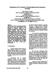
1. Introduction The multilayer mirror, which can reflect cold and very cold neutrons, is one of powerful neutron optical devices for interferometry. In addition to utilization of the long-wavelength neutrons, accurate alignment of multilayer mirrors with a large distance makes it possible to increase interaction time of neutrons with external potentials in the interferometer. Such a multilayer interferometer will be more sensitive in phase detection than the conventional silicon singlecrystal interferometers, and contribute to precise measurements of small interactions. We have recently developed a new type of multilayer neutron interferometer [1]. The multilayer interferometer consisted of a pair of beam splitting etalons (BSEs) (Figure 1) [2] with an air gap of 189 µm in spacing. Two paths of the interferometer were completely separated with a center-to-center distance of 328 ± 9 µm at an incident angle of 0.99 ± 0.05 degrees, while the previous multilayer interferometers had almost overlapped paths. Clear interferograms with maximum contrast of 67 % were also successfully observed. This progress enables us to carry out experiments in more various configurations than before. As one of the configurations, we demonstrated the optical thickness measurement of a phase object inserted into the one-side path using the multilayer interferometer. 2. Experiment and discussion The experimental setup is shown in Figure 2. A Jamin-type interferometer consisted of a pair of BSEs. In the interferometer, the incident neutron waves were firstly converted to superposition of the spin-up and spin-down states by the polarizer and the first π/2 RF spin flipper: √12 (|↑⟩ + |↓⟩). The superposition state was then split spatially by the first BSE. For the symmetric geometry, Published under licence by IOP Publishing Ltd
1
5th European Conference on Neutron Scattering Journal of Physics: Conference Series 340 (2012) 012039
IOP Publishing doi:10.1088/1742-6596/340/1/012039
magnetic magnetic mirror mirror (filter) spin-up spin-down
nonmagnetic mirror
54 mm
Figure 1. Schematic view (left) and photograph (right) of a beam splitting etalon (BSE). The BSE separates the incident spin superposition state into two parallel paths with the spin-up and the spin-down states.
neutron beam
spin-up
with phase object 2nd silicon spin-down BSE plate
slit π/2 flipper
π/2 flipper π flipper
polarizer
spin-up
slit
phaseshiftercoil
analyzer
detector
1st BSE spin-down
without phase object
Figure 2. Experimental setup. A weak magnetic field of about 10 G was generated vertically by a guide coil all over the beam (omitted in the figure). The distance between two BSEs was 300 mm. (
)
each spin state was reversed by the π RF spin flipper: √12 (|↑⟩ + |↓⟩) → √12 |↓⟩ + e2iχπ |↑⟩ , where χπ is the phase of oscillating magnetic field in the π RF spin flipper relative to the other π/2 RF spin flippers, and the phase factor e2iχπ is due to the spin state transition [3]. After the spin reversal, the spatially separate paths were recombined by the second BSE. Finally, the spin state from each path to the spin-up state by the second π/2 RF spin ( was converted ) flipper and the analyzer: 21 |↑⟩ + e2iχπ |↑⟩ . The interferograms were obtained by scanning the relative phase χπ . The change of χπ of 180 degrees gave a interferograms of one cycle. For the present measurement, a solenoid as a phase-shifter-coil was arranged behind the second BSE. The experiment was carried out at the monochromatic cold neutron beamline MINE2 [4] of Japan Research Reactor No.3 (JRR-3) in Japan Atomic Energy Agency (JAEA). The mean wavelength of the beam was λ0 = 0.88 nm with a bandwidth of 2.7% in full width at half-maximum. As verified in the previous studies [5, 6], the contrast of interferograms in the multilayer interferometer is proportional to the coherence function Γ(σk , L0 ) as [
1 Γ(σk , L0 ) = exp − (σk L0 )2 2
]
,
(1)
when we use semi-monochromatic beam with a mean wavenumber k0 and the standard deviation σk of Gaussian distribution. L0 is the optical path difference between the two paths and L0 of zero makes an “echo point”, that is, the maximum contrast point.
2
5th European Conference on Neutron Scattering Journal of Physics: Conference Series 340 (2012) 012039
IOP Publishing doi:10.1088/1742-6596/340/1/012039
In the case of the present demonstration, L0 is expressed as L0 = LB + Lb + Li
.
(2)
LB was provided by the phase-shifter-coil. The phase object inserted into the one-side path caused Lb . Li arose from the shift of relative angle between two BSEs. LB was proportional to the current j supplied to the phase-shifter-coil as LB = −αB j
.
(3)
The coefficient αB of the coil, which was also established in the previous studies [6], was 9.1λ0 /A. The insert was a silicon plate with the thickness DSi of 600 ± 25 µm. Lb is therefore expressed as Lb = − (n(k0 ) − 1) DSi 2πνb ≃ DSi , k02
(4) (5)
where n is the refractive index of the material for slow neutrons, b is the neutron scattering length of the nucleus, ν is the average number density, and k0 is the neutron wavenumber. The phase-shifter-coil induced the optical path differences LB of 0, 9.1λ0 , 18λ0 , 27λ0 , and 36λ0 , corresponding to the currents of 0, 1, 2, 3, and 4 A, respectively. These optical path differences affected the contrast of interferograms according to Equation 1. Four times measurements of interferograms at each current were carried out iteratively with/without the silicon plate. The sequential change of the contrast are shown in Figure 3 and 4. The transition of average contrast for each data set is shown in Figure 5. These transitions were fitted to Gaussian curves with a common σk and maximum contrast. The fitting gave the common σk of 0.079 ± 0.008 nm−1 , which reproduced well the wavelength dispersion of 0.082 nm−1 at the MINE2 beamline. The optical path difference Lb of the inserted silicon plate caused an echopoint-shift. The observed echo-point-shift was 15.1 ± 1.9λ0 . Within the margin of error, this shift was consistent with the expected value of 17.4 ± 0.7λ0 calculated by using the number of density ν of 5.00 × 10²² , and the scattering length b of 4.15 fm. 3. Conclusions We have succeeded in measuring the optical thickness of the phase object inserted into the one-side path for the first time using the multilayer neutron interferometer. This measurement demonstrated the functional feature of completely separate paths in our new interferometer. With improved phase stability we can advance this pilot experiment into precise measurements, for example, measurement of neutron scattering lengths [7] for the study of many-body-force between nucleons. Cold neutron interferometers have a great advantage in measuring scattering lengths because the phase shift due to the nuclear interaction is proportional to the square of neutron wavelength as shown in Equation 5. Acknowledgments This work was primarily supported by the interuniversity program for the common use of JAEA and KURRI. This work was also assisted financially by a Grant-in-Aid for Scientific Research (B) (No. 19340065) of JSPS, a Grant-in-Aid for Creative Scientific Research (No. 19gs0210) of MEXT, and a 47th Toray Science and Technology Grant. One of the authors (Y. S.) was supported by the JSPS Research Fellowships for Young Scientists and the Junior Research Associates Program of RIKEN.
3
5th European Conference on Neutron Scattering Journal of Physics: Conference Series 340 (2012) 012039
IOP Publishing doi:10.1088/1742-6596/340/1/012039
Phase-shifter-coil current
0A
1A
2A
3A
4A
140
Run number
Run1
70
0
Counts / 75 s
140
Run2
70
0 140
Run3
70
0 140
Run4
70
0 0
90
180
0
90
180
0
90
180
0
90
180
0
90
180
Phase of RF magnetic field in π flipper [deg.]
Figure 3. Transition of interferograms due to additional optical path differences induced by magnetic field of the phase-shifter-coil. No phase object was inserted into any paths of the interferometer. All the data were fitted by sine curves with the cycle fixed at 180 degrees.
Phase-shifter-coil current
0A
1A
2A
3A
4A
140
Run number
Run1
70
0
Counts / 75 s
140
Run2
70
0 140
Run3
70
0 140
Run4
70
0 0
90
180
0
90
180
0
90
180
0
90
180
0
90
180
Phase of RF magnetic field in π flipper [deg.]
Figure 4. Transition of interferograms due to additional optical path differences induced by magnetic field of the phase-shifter-coil. A silicon plate was inserted into the one-side path of the interferometer. All the data were also fitted by sine curves with the cycle fixed at 180 degrees.
4
5th European Conference on Neutron Scattering Journal of Physics: Conference Series 340 (2012) 012039
0.5
IOP Publishing doi:10.1088/1742-6596/340/1/012039
17.4 ± 0.7λ0 (expected)
Contrast
0.4 0.3 0.2 15.1 ± 1.9λ0 0.1 0
0
1 2 3 4 5 Phase-shifter-coil current [A]
6
Figure 5. Variation in average contrast of four times measurements. Solid circles and open triangles indicate the case of Figure 3 and 4, respectively. Observed shift of echo point corresponds to optical thickness of about 600-µm-thick silicon plate for 0.88-nm neutrons.
References [1] Seki Y, Funahashi H, Kitaguchi M, Hino M, Otake Y, Taketani K and Shimizu M H 2010 J. Phys. Soc. Jpn. 79 124201. [2] Kitaguchi M, Funahashi H, Nakura T, Hino M and Shimizu M H 2003 Phys. Rev. A 67 033609. [3] Yamazaki D 2002 Nucl. Instrum. Methods Phys. Res., Sect. A 488 623. [4] Suzuki J, Soyama K, Tasaki S and Ebisawa T 2001 Proc. 15th Meet. Int. Collaboration on Advanced Neutron Sources (Tsukuba: JAERI) p 547. [5] Morikawa Y and Otake Y 1990 Nuovo Cimento B 105 507. [6] Kitaguchi M, Funahashi H, Nakura T, Taketani K, Hino M, Otake Y and Shimizu M H 2003 J. Phys. Soc. Jpn. 72 3079. [7] Huber M G, Arif M, Black T C, Chen W C, Gentile T R, Hussey D S, Pushin D A, Wietfeldt F E and Yang L 2009 Phys. Rev. Lett. 102 200401.
5