Sensors2012, 12, 3269-3280; doi:10.3390/s120303269 OPEN ACCESS
sensors ISSN 1424-8220 www.mdpi.com/journal/sensors Article
Design and Fabrication of Single-Walled Carbon Nanonet Flexible Strain Sensors Ya-Ting Huang 1, Shyh-Chour Huang 1,*, Chih-Chao Hsu 2, Ru-Min Chao2 and Trung Kien Vu 1 1
2
Department of Mechanical Engineering, National Kaohsiung University of Applied Sciences, Kaohsiung 80778, Taiwan; E-Mails:
[email protected] (Y.-T.H.);
[email protected] (T.K.V.) Systems and Naval Mechatronics Engineering, National Cheng-Kung University, Tainan 701, Taiwan; E-Mails:
[email protected] (C.-C.H.);
[email protected] (R.-M.C.)
* Author to whom correspondence should be addressed; E-Mail:
[email protected]; Tel.: +886-7-381-4526 ext. 5313; Fax: +886-7-383-1373. Received: 21 January 2012; in revised form: 28 February 2012 / Accepted: 29 February 2012 / Published: 7 March 2012
Abstract: This study presents a novel flexible strain sensor for real-time strain sensing. The material for strain sensing is single-walled carbon nanonets, grown using the alcohol catalytic chemical vapor deposition method, that were encapsulated between two layers of Parylene-C, with a polyimide layer as the sensing surface. All of the micro-fabrication was compatible with the standard IC process. Experimental results indicated that the gauge factor of the proposed strain sensor was larger than 4.5, approximately 2.0 times greater than those of commercial gauges. The results also demonstrated that the gauge factor is small when the growth time of SWCNNs is lengthier, and the gauge factor is large when the line width of the serpentine pattern of SWCNNs is small. Keywords: Parylene-C; single-walled carbon nanonets; strain sensor
1. Introduction Bone strains are vital factors for osteogenic responses [1]. A complete understanding of the biomechanical behavior of human bone under daily activity conditions is crucial for the development of post-surgical therapies, which must be adapted to the healing stage [2]. Real-time monitoring of the musculoskeletal condition through bone strain recording would help doctors gain instant and detailed
Sensors 2012, 12
3270
information for rehabilitation monitoring, as well as improve clinical studies for advanced orthopedic operations [3]. In vivo bone strain measurement through an implantable sensor is one of the most suitable solutions for these requirements [4]. A high-sensitivity implantable monitoring sensor is required for measuring strain because strain is an easy and quick way to determine surface variation of the bone or the amount of joint compression. Metallic foil gauges are commercially available because of their low cost and stable fabrication, but they have some disadvantages, such as low sensitivity, large size, and low biocompatibility, which limit their application for long-term solutions. The large pattern of metallic foil gauges also presents difficulty in implantable surgery and causes patient discomfort. Because of their reversible electromechanical [5,6] and biocompatible [7] characteristics, carbon nanotubes (CNTs) are excellent for bone strain gauges, in which the strain would be measured by recognizing electrical resistance changes [8–15]. CNTs are nanoscale materials that have interesting electrochemical, mechanical, and biological properties. They are macromolecules of carbon, and their elastic modulus is 1 TPa [16]. Two types of CNTs are available, that is, single-walled carbon nanotubes (SWCNTs) and multi-walled carbon nanotubes (MWCNTs). CNTs are assumed to be biocompatible with osteoblast cells, which have piezoresistive effect (the theoretical ability of the material for strain sensing) of up to 1,000, and a diameter of approximately 1 nm [17,18]. CNTs are fabricated using laser ablation, arc-discharge, and catalytic chemical vapor deposition (CCVD). However, laser ablation and arc-discharge do not result in mass growth of CNTs, and cannot be integrated into the MEMS process. However, CCVD can achieve mass growth of CNTs, and also allows sensors to increase the opportunity for major commercial productions. CNTs become carbon nanonets with a certain thickness by using CCVD. Thereby, the presented sensor was designed and fabricated with piezoresistive effect and MEMS process. The implantable sensor requires three parts, namely substrate, piezoresistive material, and a waterproof layer. Parylene-C is a biocompatible flexible, and waterproof polymer, that is widely used for producing a variety of products, such as micropumps, micronozzles, neural probes, and cell manipulation platforms. The Young modulus of Parylene is between 2 and 5 GPa, which is lower than those of the human cortical bone (20.5 GPa) and trabecular bone tissue (18 GPa). Therefore, Parylene can be fully attached to the bone [19–21]. In this study, a flexible strain sensor was designed and fabricated based on the piezoresistive effect of single-walled carbon nanonets (SWCNNs), and Parylene-C was used as the waterproof layer for ensuring biocompatibility. 2. Sensor Design and Fabrication 2.1. Design The commercial strain sensors were assembled by wire, metal foil (sensing element), laminate film (waterproof layer), and a base substrate. The resistance of the metal foil gauge changes with strain during stress loading, and the strain can be determined by the change in electrical resistance. A serpentine pattern is commonly used for commercial strain sensors. In this study, we used single-walled carbon nanonets (SWCNNs) to replace the customary metal foil. Parylene-C was used as
Sensors 2012, 12
3271
the waterproof layer, and another layer of Parylene-C was used as the base (Figure 1(a)). Further, to determine the Gauge Factor scale-down effects for the CNNs under different geometries, a serpentine pattern with different numbers of turns, a constant length and various widths of CNN was designed (Figure 1(b)). Figure 1. Strain sensor design: (a) 3D diagram (b) dimension of SWCNNs pattern. (a)
2.2. Fabrication Process The manufacturing process for the presented strain sensing device is summarized in Figure 2. First, a 500 nm oxide layer is grown on a silicon wafer (Figure 2(a)). The surface of the SiO2 layer is not naturally hydrophilic. In order to make the surface hydrophilic for uniform coating with nanosize metal catalysts, the surface of the oxide substrate is first treated with standard cleaning solutions 1 and 2 (SC1 and SC2) then, subsequently dipped in a Co/Mo solution. After dipping, the wafer was placed into the alcohol catalytic chemical vapor deposition (ACCVD) apparatus for growing CNNs (Figure 2(b)). Next, Reactive Ion Etching was used to etch CNNs to form the serpentine pattern (Figure 2(c)). The wafer with the SWCNN pattern was subsequently placed into the Parylene deposition equipment (Specialty Coating System, Model PDS-2010) for a 6 µm thick Parylene-C coating. A thermal release tape (green layer) was used to bond the Parylene-C layer with the CNN serpentine pattern (Figure 2(d,e)). Figure 2. Fabrication process.
Sensors 2012, 12
3272 Figure 2. Cont.
Then, a gold layer is used as the source drain electrodes using the lift-off process (Figure 2(g)). Finally, the device was placed into the Parylene deposition equipment again for another Parylene-C coating to form the waterproof layer. After these fabrication steps, the presented strain sensor was released from the thermal release tape by heating for 1 min at 120 °C. 2.3. Single-Walled Carbon Nanonets Growth In this study, the sensing material of the sensor, that is, single-walled carbon nanonets, which were grown using alcohol catalytic chemical vapor deposition equipment (ACCVD, as shown in Figure 3), was provided by National Nano Device Laboratories (NDL, Taiwan). The entire process is shown in Figure 4. Figure 3. ACCVD equipment diagram [22].
The process used dip set (Dip) to attach the catalytic metal to the fragments. The amount of attached catalytic metal attached is crucial; therefore, the SC1 and SC2 solutions were boiled to temporarily increase the surface hydrophilicity. The SC1 solution was prepared with H2O2-NH4OH-H2O in the ratio of 1:1:5, heated to 75 °C for 20 min. Subsequently, H2O2-HCl-H2O in the ratio of 1:1:6 was used to prepare the SC2 solution, which was heated to 75 °C for another 20 min. Then, the device was cleaned with deionized water and dipped in catalytic metal-Co/Mo solution, the ratio of which was
Sensors 2012, 12
3273
0.08 wt.% (Co: Mo-C2H5OH), for 10 min. Subsequently, the ACCVD was heated to 400 °C, and the stage quartz fragments were placed and sintered into ACCVD for 7 min and 30 s to allow the catalytic metal to be fixed on the Si substrate. The temperature in the ACCVD process was set to 750 °C, which resulted in gas formation, to restore the oxidation of the catalytic metal. The ACCVD was maintained at 750 °C environment during the growth stage of single-walled carbon nanonets for carbon—alcohol vapor in the chamber. Finally, only Ar gas was passed into the chamber for cooling to complete the growth of the single-walled carbon nanonets. Figure 4. Single-walled carbon nanonets growth process flowchart. SC1
H O :NH OH:H O =1:1:5
SC2
H O :HCl:H O =1:1:5
increase surface hydrophilicity
Dip Fragment
Sintering
Co Reduction
2
2
2
4
2
2
2
Co:Mo:C H OH =0.08wt% 2
5
400°C
400°C~750°C , NH
3
ACCVD Nano Carbon network growth
750°C , C H OH 2
5
Cooling
2.4. Fabrication Results The inset in Figure 5 shows a closer view of the CNNs and Parylene-C, another closer view shows the transfer result with the 10 µm pattern after the Parylene-C is pulled off the silicon substrate. Figure 5. Nanocarbon network and SEM images of Parylene-C.
Sensors 2012, 12
3274
In addition, the wider view of Figure 5 shows the CNNs serpentine pattern. Further, after the micro-fabrication, the device with thermal release tape is placed on the hot plate, and the presented strain sensor is released from the thermal release tape by heating for 1 min at 120 °C. The final flexible nano-carbon network strain sensor is shown in Figure 6. Figure 6. Flexible nanocarbon network strain sensor complete map.
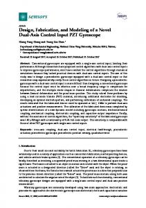
3. Electromechanical Testing An acrylic plate, of 200 mm length with a width of 50 mm, was placed in an Instron testing machine (model 1130). The Parylene-based SWCNNs strain sensor was attached on the plate with special glue “M-Bond 200” for the device at the length of 10 cm and the rear of the plate. Figure 7. The photo of the tensile testing system.
The plate was then attached to a commercial metallic foil strain sensor (KYOWA Electronic Instruments Co., LTD). A strain amplifier (KYOWA, model DPM-711B) was used to obtain the
Sensors 2012, 12
3275
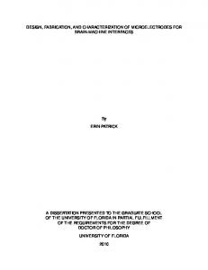
output strain signal as voltage (1 V = 5,000 micro-strain) from the commercial metallic foil strain sensor (The voltage input for the metal foil gauge is 3.7 V). The output signal of resistance from the Parylene-based SWCNNs strain sensor was acquired by a data logger system (Keithley, model 2700), the strain of the plate was measured by a 1/4 bridge Wheatstone bridge with a commercial metallic gauge. The tensile testing experiment is shown in Figure 7. 4. Results and Discussions In tensile testing, a commercial strain sensor was used to measure the strain of the test piece. Figure 8 shows the resistance variation and strain variation of a commercial strain sensor and the SWCNNs strain sensor (with growing time of 20 min, line width of 10 μm). Figure 8 shows that, within 0 to 15 s, no variation of resistance of commercial strain sensor occurred; however, a slight variation resistance of SWCNNs strain sensor was observed. Figure 8. SWCNNs strain sensors and commercial strain sensors measurement.
The tensile test specimens began to stretch within 15 to 33 s, and the resistance values of the commercial sensors and SWCNNs sensors increased. The strain curves of the commercial sensors and SWCNNs sensors began to overlap slowly when the stretch reached 1,800 microstrains. The noise did not have any interference effect on the SWCNNs strain sensors when the strain amount was sufficiently large. The curve began to produce non-linear phenomena when the stretch reached 4,000 microstrains, which indicates that the tensile test specimens began to produce plastic deformation. Therefore, the stretch test scope was limited to 3,500 microstrains in the later tests. Figures 9 and 10 show the experimental results for the tensile test of the Parylene-based SWCNN strain sensors. Nine strain sensors with various lengths were obtained. The relative changes of the resistance of the strain sensors were increased when tension loading was applied. The gauge factor was calculated from the graph by the following equation:
△R/R=G × ε
(1)
Sensors 2012, 12
3276
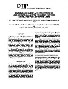
where ΔR/R is the relative change in resistance, and ε is the strain measured by the strain gauge. G is the gauge factor of the SWCNNs strain sensors. The average gauge factor of the SWCNN strain sensors was 5.05. The gauge factors were higher than those of the commercial metallic foil strain gauge (the GF of the metal foil gauge is 2.1). Figure 9. The strain sensitivities of the SWCNN strain sensor (growth time of 10 min, sample 2).
Figure 10. The strain sensitivities of the SWCNN strain sensor (growth time of 20 min, sample 4).
Figure 9 shows the single-walled carbon nanonet (growth time of 10 min and Sample 2) with the strain sensitivities of the strain sensor in the tensile test. We obtained the gauge factor of the sensor by
Sensors 2012, 12
3277
calculating the slope of the curve from Figure 9. As shown in Figure 9, the gauge factor of 10 μm is 6.09 to 6.44, that of 30 μm is 5.32 to 5.48, and that of 50 μm is 4.58 to 4.92. Similarly, Figure 10 shows the single-walled carbon nanonet (growth time of 20 min and Sample 4) with the strain sensitivities of the strain sensor in tensile test. As shown in Figure 10, the gauge factor of 10 μm is 5.49 to 5.56, that of 30 μm is 4.92 to 4.99, and that of 50 μm is 4.64 to 4.71. As shown in Figures 9 and 10, the sensors with the same width have measure curves that are closer to each other, which indicate the proximity of the gauge factor. The relationship between gauge factors and resistances is shown in Figure 11. As seen in this figure, generally, the gauge factor of SWCNNs sensors with a growth time of 10 min is larger than that with a growth time of 20 min. Figure 11. The relationship of resistance andgauge factor.
The line width effect on the gauge factor is shown in Figure 12. As shown, under the same number, the small line width has a large gauge factor. The difference in the number width and the gauge factor curve is smaller when the growth time is 20 min. This indicates that the higher the density of the single-walled carbon nanonet, the length change from the number has a smaller effect on the relation curve difference between line width and gauge factor. Figure 13 shows the relationship of resistance and gauge factor. As seen resistance and gauge factor are positively correlated. The electronic conductive path decrease as the network density decreases, resulting in an increase in resistance. Also, when the device is during a tension loading, the sparse network became more sparse, that resulting in an increase in gauge factor. Under the same line width and bar number, the large resistance indicates that the density of the single-walled carbon nanonet is low.
Sensors 2012, 12
3278 Figure 12. Therelationship of line width and gauge factor.
Figure 13.The relationship of resistance andgauge factor ( with same line width and number of bar).
5. Conclusions This study presents the design and fabrication of a strain sensor that uses single-walled carbon nanonets for strain sensing. The sensor was encapsulated between two layers of Parylene-C. These flexible strain sensors exhibited excellent strain sensitivities, and can be used to measure bone surface strain.
Sensors 2012, 12
3279
Acknowledgements The authors acknowledge and thank the National Science Council and National Nano Device Laboratories for financial support of this work under contract Number NSC 99-2221-E-151-004-MY2 and NDL98-C02M2P-091. References 1. 2.
3. 4. 5.
6.
7. 8. 9. 10. 11.
12. 13. 14.
15.
Yang, P.F.; Bruggemann, G.P.; Rittweger, J. What do we currently know from in vivo bone strain measurements in humans? J. Musculoskelet & Neuronal Interact. 2011, 11, 8-20. Umbrecht, F.; Wagli, P.; Dechand, S.; Gattiker, F.; Neuenschwander, J.; Sennhauser, U.; Hierold, C. Wireless implantable passive strain sensor: Design, fabrication and characterization. J. Micromechanic. Microengineer. 2010, doi:10.1088/0960-1317/20/8/085005. Yang, G.Y.; Johnson, G.; Tang, W.C.; Keyak, J.H. Parylene-based strain sensors for bone. IEEE Sens. J. 2007, 7, 1693-1697. Yuehuei, H.A.; Robert, A.D. Mechanical Testing of Bone and the Bone-Implant Interface; CRC Press: Boca Raton, FL, USA, 2000. Tombler, T.W.; Zhou, C.W.; Alexseyev, L.; Kong, J.; Dai, H.J.; Lei, L.; Jayanthi, C.S.; Tang, M.J.; Wu, S.Y. Reversible electromechanical characteristics of carbon nanotubes under local-probe manipulation. Nature 2000, 405, 769-772. Semet, V.; Binh V.T.; Guillot, D.; Teo, K.B.K.; Chhowalla, M.; Amaratunga, G.A.J.; Milne, W.I.; Legagneux, P.; Pribat, D. Reversible electromechanical characteristics of individual multiwall carbon nanotubes. Appl. Phys. Lett. 2005,87, 223103. Lin, C.M.; Lee, Y.T.; Yeh, S.R.; Fang, W. Flexible carbon nanotubes electrode for neural recording. Biosens. Bioelectron. 2009, 24, 2791–2797. Lu, J.W.; Wang, W.L.; Liao, K.J.; Wan, B.Y. Strain-induced resistance changes of carbon nanotube films. Int. J. Mod. Phys. B. 2005, 19, 627-629. Jang, H.S.; Lee, Y.H.; Na, H.J.; Nahm, S.H. Variation in electrical resistance versus strain of an individual multiwalled carbon nanotube. J. Appl. Phys. 2008, 104,114304 Park, M.; Kim, H.; Youngblood, J.P. Strain-dependent electrical resistance of multi-walled carbon nanotube/polymer composite films. Nanotechnology 2008, 19,055705. Slobodian, P.; Riha, P.; Lengalova, A.; Olejnik, R.; Kimmer, D.; Saha, P. Effect of compressive strain on electric resistance of multi-wall carbon nanotube networks. J. Exp. Nanosci. 2011, 6, 294-304. Dharap, P.; Li, Z.L.; Nagarajaiah, S.; Barrera, E.V. Nanotube film based on single-wall carbon nanotubes for strain sensing. Nanotechnology 2004, 15, 379-382. Li, X.; Levy, C.; Elaadil, L. Multiwalled carbon nanotube film for strain sensing. Nanotechnology 2008, 19, 045501. Yamada, T.;Hayamizu, Y.; Yamamoto, Y.;Yomogida, Y.; Izadi-Najafabadi, A.; Futaba, D.N.; Hata, K. A stretchable carbon nanotube strain sensor for human-motion detection. Nature Nanotechnol. 2011, 6, 296-301. Chang, N.K.; Su, C.C.; Chang, S.H. Fabrication of single-walled carbon nanotube flexible strain sensors with high sensitivity. Appl. Phys. Lett. 2008, 92, 063501.
Sensors 2012, 12
3280
16. Liu, Y.; Chakrabartty, S.; Gkinosatis, D.S.; Mohanty, A.K.; Lajnef, N. Multi-Walled Carbon Nanotubes/Poly(L-lactide) Nanocomposite Strain Sensor for Biomechanical Implants. In Proceedings of IEEE Biomedical Circuits and Systems Conference, BIOCAS 2007, Montreal, QC, Canada, 27–30 November 2007; pp. 119-122. 17. Stampfer, C.; Jungen, A.; Linderman, R.; Obergfell, D.; Roth, S.; Hierold, C. Nanoelectromechanical displacement sensing based on single-walled carbon nanotubes. Nano Lett. 2006, 6, 1449-1453. 18. Jan, E.; Kotov, N.A. Successful differentiation of mouse neural stem cells on layer-by-layer assembled single-walled carbon nanotube composite. Nano Lett. 2007, 7, 1123-1128. 19. Giacchino, L.; Tai, Y.C. Parylene-membrane piezoresistive pressure sensors with XeF2-Etched cavity. In Proceedings of 2008 IEEE Sensors, Lecce, Italy, 26−29 October 2008; pp. 1568-1571. 20. Ziegler, D.; Suzuki, T.; Takeuchi, S. Fabrication of flexible neural probes with built-in microfluidic channels by thermal bonding of parylene. J. Microelectromech. Syst. 2006, 15, 1477-1482. 21. Yang, G.Y.; Johnson, G.; Tang, W.C.; Keyak, J.H. Parylene-based strain sensors for bone. IEEE Sens. J. 2007, 7, 1693-1697. 22. Shiau, S.H.; Liu, C.W.;Gau, C.; Dai, B.T. Growth of a single-wall carbon nanotube film and its patterning as an n-type field effect transistor device using an integrated circuit compatible process. Nanotechnology 2008, 19, 105303. © 2012 by the authors; licensee MDPI, Basel, Switzerland. This article is an open access article distributed under the terms and conditions of the Creative Commons Attribution license (http://creativecommons.org/licenses/by/3.0/).