4112
IEEE TRANSACTIONS ON MAGNETICS, VOL. 47, NO. 10, OCTOBER 2011
Design Considerations for Achieving High Radial Stiffness in an Attraction-Type Magnetic Bearing With Control in a Single Direction Isaias da Silva , José R. Cardoso , and Oswaldo Horikawa Department of Chemical Engineering, Federal University of São Paulo-UNIFESP, Diadema-SP, Brazil Escola Politécnica, University of São Paulo-USP, São Paulo-SP, Brazil In past work, the authors have proposed a radial magnetic bearing architecture where the rotor was kept suspended only by means of magnetic forces produced by permanent magnets working in attraction mode and the rotor was actively controlled only in one degree of freedom (d.o.f.), i.e., its axial direction. Although the presented architecture is simpler than those bearings with active control in two or more d.o.f., it presented limitations mainly of low radial stiffness. So, in this context this paper discusses ways to enhance the radial stiffness in this kind of bearing and presents simplified analytical methods used to find magnets and actuator optimal dimensions that gives both ring magnets radial stiffness and actuator force/current ratio maximum intensities. Index Terms—Hybrid magnetic bearing, single axis controlled magnetic bearing, stiffness improvement.
I. INTRODUCTION
I
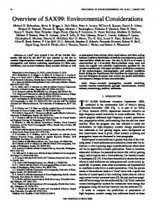
N A PAST work [1], the authors have presented a radial magnetic bearing with control only in one degree of freedom of a rotor. Fig. 1 shows the schematics of such bearing. A rotor having a permanent magnet fixed to each of its ends passes through two sets of a ring permanent magnets combined with an electromagnet. All magnets are axially magnetized and mounted so as to have an attraction force between facing magnets. These attraction forces assure a positive rigidity in terms of radial displacements and tilting of the rotor. Since the rigidity in terms of axial displacement is negative, in this direction the stability is assured by an active control loop composed of a gap sensor, a controller, a power amplifier, and two electromagnets. Concerning this bearing, this work discusses strategies to improve both its radial stiffness and actuator force/current ratio.
Fig. 1. Single axis controlled magnetic bearing.
II. IMPROVEMENT IN THE RADIAL STIFFNESS Yonnet [2] presented in his works an analytical formulation for radial and axial stiffness in a pair of ring magnets, operating in attraction mode, placed concentrically, as depicted in Fig. 2. Although restricted, these equations can be used as a first step in the design and analysis of the magnetic bearings passive portion and the results used as boundary conditions in a finite element analysis, saving computation time and providing directions to improve bearing performance. Yonnet’s equations can also be used to find the ring magnets dimensions and magnetization values that maximize the radial stiffness. This is achieved when the gap is as narrow as the mechanical clearance allows and the magnetization intensities (module of ) are as high as possible. Also, in Fig. 2 the following should be satisfied:
Fig. 2. Concentric ring magnets.
According to Earnshaw’s theorem [3], for bearings made solely of permanent magnets, the sum of bearing stiffnesses is equal to zero, i.e., (1) For ring magnets and observing Fig. 2, , which yields to
Manuscript received February 13, 2011; accepted April 11, 2011. Date of current version September 23, 2011. Corresponding author: I. da Silva (e-mail:
[email protected]). Digital Object Identifier 10.1109/TMAG.2011.2144959
and (2)
Equation (2) shows that the improvement in the radial stiffness implies the increase in the axial negative stiffness. There-
0018-9464/$26.00 © 2011 IEEE
DA SILVA et al.: DESIGN CONSIDERATIONS FOR ACHIEVING HIGH RADIAL STIFFNESS IN AN ATTRACTION-TYPE MAGNETIC BEARING
Fig. 3. Theoretical and numerical radial stiffness results. (a) Radial stiffnesses variations vs radial displacement, , when the magnet height (Fig. 2) is changing. increasing. (b) Radial stiffnesses variations vs radial displacement, , when the magnet radius,
fore, the electromagnetic actuator characteristics must be improved concomitantly. So, using a finite element software package, some numerical analyses were performed and the results compared with those given by Yonnet’s equations [2]. The ring magnets used in these analyses are Nd-Fe-B with mm, mm, mm, mm, mm, mm, and mm, see Fig. 2. The numerical and analytical results given by [2] are shown in Fig. 3. Observing this figure, one can see that because of the simplifications assumed by Yonnet’s equations there is a small divergence between numerical and analytical results. Despite of this divergence the results showed that the radial stiffness varies significantly with the ring magnets and dimensions and, as predicted by [2], the maximum stiffnesses intensities are reached when converge to zero and approaches . III. HYBRID ELECTROMAGNETIC ACTUATOR DESIGN AND ANALYSES In order to any bearing architecture be stable, the sum of all stiffnesses must be positive. However, (2) shows that the positive value of implicates in a negative value of . Thus, these stiffnesses are highly coupled. So, radial bearings are unstable along axial direction and the higher the radial stiffness, which is desired, e.g., to improve bearing radial load capacity, the higher the axial unstable stiffness. Thereby, along axial direction the necessary positive stiffness, , must be assured by a control system loop composed of electromagnetic actuators, a sensor and a controller [4]. Despite the controller worthiness to the system, the actuator plays the main role in assuring bearing axial stability; therefore its design is very significant in both the development and improvement stages of radial bearings. Generally, these stages are accomplished using numeric analyses, for example FEM [5] and [6]. Notwithstanding the use of FEM tools essential for more realistic actuator performance predictions at the design stage, it is not always possible for the designer to have previous insight into the actuator behavior, i.e., the way each parameter of the system actually alters its response, e.g., the force/current ratio, . Thereby, the use of simpler electromagnetic theory to model the actuator under development can give the designer some directions and boundary conditions besides contributing to save computational time.
4113
(Fig. 2), is
Fig. 4. The electromagnetic actuator.
So, considering the solenoidal actuator type depicted in Fig. 4 and assuming it is symmetric around the axis, the axial electromagnetic force, , exerted by the coil on magnet , assumed uniformly magnetized, i.e., , and also the magnetic force, , between this magnet and the actuator iron core can be calculated using the following procedure: a) Neglect the pure magnetic force that acts between the magnets and because this force does not affect the actuator electromagnetic force and it can be determined separately [2]. b) Determine the magnetic flux density, along the axis using Biot–Savart law, resulting in
(3)
is the average coil radius and for represents the distance from the centre of the coil to the magnet inner and outer faces, respectively. c) Using the magnet charge model [7], the interaction force between the coil and the magnet is computed according to where
(4)
4114
IEEE TRANSACTIONS ON MAGNETICS, VOL. 47, NO. 10, OCTOBER 2011
where and are the magnet volume and superficial charge densities, respectively. d) Putting the result given by (3) into (4) and using the fact that , , and solving the integral on magnet cross section, the stiffness and the force between coil and magnet along direction results in
TABLE I ACTUATOR MAIN DIMENSIONS
(5)
. Eq. (5) clearly shows the depenwhere dence on , and . e) Again, using the magnet charge model [7] and assuming that the magnet is in free space, i.e., , the field outside the magnet is computed according to:
(6) Fig. 5. Magnetic force versus current: case (I).
where is a vector that represents the distance between magnet’s faces and a point where the field need to be evaluated. So, evaluating (6), the magnet field component is
(7) f) The force between the magnet and the coil’s iron core along the axis can be determined using the Maxwell stress tensor [8] together with (7), resulting in:
Fig. 6. Magnetic force versus current: case (I).
IV. ANALYTICAL VERSUS NUMERICAL RESULTS COMPARISON (8)
where is the iron core cross section. g) Finally, using (5) and (8), the actuator axial resultant force is (9)
Considering the actuator of Fig. 4 and aiming improvements in the actuator gain, i.e., the force/current ratio, , three different sets of dimensions are considered for comparison: cases (I)–(III) in Table I. Calculated curves are shown in Figs. 5–8. In the figures, results calculated using analytical expressions are shown together with those obtained by numerical analysis performed using the finite element method (Ansys Maxwell 3D). As depicted in Figs. 5 and 6, does not vary significantly, despite the iron in the actuator core. The iron contributes only in
DA SILVA et al.: DESIGN CONSIDERATIONS FOR ACHIEVING HIGH RADIAL STIFFNESS IN AN ATTRACTION-TYPE MAGNETIC BEARING
4115
due to the simplifications assumed when formulating the theoretical (5) and (8), e.g., the fringing effect was not considered in the theoretical model but it is considered in FEM analysis. V. CONCLUSIONS
Fig. 7. Magnetic force versus current: case (II).
This work presented some guidelines to aid the design of the magnetic pairs and the electromagnetic actuators so as to improve the radial stiffness in a single axis controlled magnetic bearing. Based on ordinary analytical models the design criteria to reach both the highest magnetic radial stiffness and force/current ratio were shown. The analytical results were compared with several numerical results obtained by FEM analyses which demonstrated the viability of the proposed methodology in helping to enhance the actuator design in the first development stages. One other aspect that should be considered on improving stiffness characteristics of this bearing is the fact that, as presented, the actuators work with the magnetic circuit opened, i.e., partially closed by the air. The study of a bearing topology with a closed magnetic circuit will be considered in another work. ACKNOWLEDGMENT This research project is supported by Fundação de Amparo à Pesquisa do Estado de São Paulo, FAPESP, process number 2006/58773-1. The authors thank Professor Sergio Gama from Federal University of São Paulo, UNIFESP, for his invaluable comments and suggestions.
Fig. 8. Magnetic force versus current: case (III).
shifting up the forces, as predicted by (8), not affecting as commented in (5). The same is observed with respect to Figs. 7 and 8. In these cases, the iron core was suppressed and some actuator parameters were varied (cases II and III, Table I). These changes resulted in almost 50% increase in without any elevation in the number of coil turns. In fact, higher values of are reached when the lengths, and are reduced, the is kept as narrow as the mechanical clearance allows, the magnet cross section is increased and the magnet magnetization is as high as possible. On the other hand, the value of must not be very high when compared with magnet , because (5) shows that as higher is as lower is the . The divergence between theoretical and FEM results in Figs. 7 and 8 is mainly
REFERENCES [1] I. Silva and O. Horikawa, “An 1-dof controlled attraction type magnetic bearing,” IEEE Trans. Ind. Applicat., vol. 36, no. 4, pp. 1138–1142, 2000. [2] J. P. Yonnet, “Permanent magnetic bearing and couplings,” IEEE Trans. Magn., vol. 17, no. 1, pp. 1169–1173, 1981. [3] S. Earnshaw, “On the nature of the molecular forces which regulate the constitution of the luminiferous ether,” Trans. Cam. Phil. Soc., vol. 7, pt. 1, pp. 97–112, 1839. [4] I. Silva and O. Horikawa, “Experimental development of a one-degree of freedom controlled magnetic linear bearing,” IEEE Trans. Magn., vol. 41, no. 10.1109, pp. 4257–4260, 2005. [5] M. V. K. Chari and J. D’ Angelo, “Finite element analysis of magnetomechanical devices,” in Proc. 5th Int. Workshop on Re-Co P.M., K. J. Strnat, Ed., Roanoke, VA, 1981, pp. 237–256. [6] P. P. Silvester and R. L. Ferrari, Finite Element for Electrical Engineers, 2nd ed. New York: Cambridge Univ. Press, 1990. [7] E. P. Furlani, Permanent Magnet and Electromechanical Devices. New York: Academic Press, 2001. [8] D. A. Lowther and P. P. Silvester, Computed-Aided Design in Magnetics. New York: Springer-Verlag, 1986.