winding transformers, electric vehicles. I. INTRODUCTION. BATTERY LIFE is one of the major factors presently limiting the realization of economically viable ...
28
IEEE TRANSACTIONS ON INDUSTRY APPLICATIONS, VOL. 35, NO. 1, JANUARY/FEBRUARY 1999
Design Considerations for Charge Equalization of an Electric Vehicle Battery System Nasser H. Kutkut, Member, IEEE, Herman L. N. Wiegman, Deepak M. Divan, Fellow, IEEE, and Donald W. Novotny, Fellow, IEEE
Abstract— Charge equalization for series-connected battery strings has important ramifications on battery life. It enhances the uniformity of the battery cells and, hence, improves the life of the battery as a whole. A new charge equalization technique for a series string of battery cells has been recently proposed by the authors. The basic technique utilizes a simple isolated dc-to-dc converter with a capacitive output filter along with a multiwinding transformer. The possibility of integrating the trickle charge function with the charge equalization function is potentially very attractive, as it can lead to an efficient and low-cost implementation.
converters and magnetic components with tightly controlled parasitics and highly symmetrical transfer characteristics. The coaxial winding transformer has been demonstrated to have these properties. In this paper, design considerations for the proposed technique as applied to an EV battery system will be discussed. Experimental data will be provided to verify the concepts presented.
Index Terms— Battery charging, charge equalization, coaxial winding transformers, electric vehicles.
II. SERIES-CONNECTED BATTERY MODULES
I. INTRODUCTION
B
ATTERY LIFE is one of the major factors presently limiting the realization of economically viable electric vehicles (EV’s). In an EV application, the main motive power source is realized using series-connected battery strings with bus voltages in the range of 300–400 V. It has been shown that battery life, under a normal operating cycle, tends to degrade almost exponentially as the battery string length is increased. Series-connected battery strings are prone to dramatic reduction in life and potential damage if high rate charging is continued after the onset of gassing. In order to improve battery life, individual cells need to be maintained at an equalized charge level. A new technique for charge equalization of a seriesconnected battery string has been proposed by the authors in [1]. The proposed technique utilizes the property of individual module voltages having the same value once they have reached the final state of charge. As a result, it is possible to use only one power converter to provide charge equalization for all the modules in the stack. In addition, the trickle charge function can be integrated with the charge equalizer to yield an efficient and low-cost implementation. However, the main challenge in implementing such a technique is the ability to realize Paper IPCSD 98–64, presented at the 1995 IEEE Applied Power Electronics Conference and Exposition, Dallas, TX, March 5–9, and approved for publication in the IEEE TRANSACTIONS ON INDUSTRY APPLICATIONS by the Industrial Power Converter Committee of the IEEE Industry Applications Society. Manuscript released for publication August 3, 1998. N. H. Kutkut is with PowerDesigners, LLC, Middleton, WI 53562 USA. H. L. N. Wiegman and D. W. Novotny are with the Department of Electrical and Computer Engineering, University of Wisconsin, Madison, WI 53706 USA. D. M. Divan is with Soft Switching Technologies Corporation, Middleton, WI 53562 USA. Publisher Item Identifier S 0093-9994(99)00453-3.
As pointed out earlier, in an EV application, the main power source is realized using series-connected battery strings. Hence, individual battery modules are charged serially. Different schemes and algorithms have been developed to achieve this task. One algorithm uses a multistep constant current charging [2]. The charging process starts with the maximum current the charger can deliver to the battery pack at low state of charge. As the state of charge builds up, the charging current is reduced in steps. Rest (cooling) periods are also incorporated in the algorithm to minimize temperature differences between the cold and warm cells. In addition, equalization charging is applied at low current levels to improve the battery capacity. A new fast charging algorithm has been recently proposed in [3]. It consists of three operational modes: an active-charge mode, an active-discharge mode, and an inactive rest mode. During the first mode, positive pulses apply energy to the battery. In the second mode, a sharp depolarization pulse of much shorter duration is applied to position the electrolyte ions away from the plates. Finally, a stabilization/rest period is used to position the ions at an optimum distance from the plate surfaces. Battery cell monitoring is used to optimize the charging algorithm. Other schemes and algorithms have been reported in the literature, as well. However, since all of these schemes deal with the battery pack as a whole, individual cell equalization cannot be easily achieved. Normal differences in cell chemistries and temperature gradients along a battery stack can lead to large nonuniformities in cell charge levels and corresponding cell terminal voltages. As a result, some of the modules will charge more quickly than others. Continued high rate charging may well result in overcharging these modules. On the other hand, if the charging process is stopped when some of the modules are fully charged, then the undercharged modules can go into polarity reversal during deep discharge.
0093–9994/99$10.00 1999 IEEE
KUTKUT et al.: CHARGE EQUALIZATION OF AN ELECTRIC VEHICLE BATTERY SYSTEM
29
Fig. 1. Charge equalization using ICE’s.
In addition, the capacity of the battery in this case will not be fully utilized. In order to prevent the adverse effects of unequalized charging of battery modules, individual modules need to be maintained at an equalized charge level. One approach to achieve this task is by using individual cell equalizers (ICE’s) across each battery module, as shown in Fig. 1 [4]. The ICE is a voltage-controlled current shunt which diverts the current away from the cell during trickle charging. This scheme prevents fully charged cells from getting overcharged while undercharged modules can still be trickle charged. The ICE scheme can be implemented using low-power dcto-dc converters across each battery module [5]. However, such a scheme is considered to be expensive due to the additional hardware and control associated with each battery module. III. PROPOSED CHARGE EQUALIZATION SCHEME A new scheme for charge equalization of a series-connected battery string has been proposed by the authors in [1]. The new proposed scheme consists of two parts: a bulk/fast charging system and a charge equalization system, as shown in Fig. 2. During fast/bulk charging, each individual battery module, or a stack of modules, is monitored for overcharging via the voltage-sensing wires. If any of these stacks reaches its nominal voltage, or if gassing is detected, bulk charging is shut off and charge equalization is enabled. The sensing wires are also used by the charge equalization circuitry. The charge equalization technique utilizes a simple isolated dc-to-dc converter with a capacitive output filter along with a multiwinding transformer, as shown in Fig. 3. The coaxial transformer is known for its properties of low and controlled leakage inductance and accurate control of all fluxes [6], [7]. These properties form the basis for realizing a fully symmetrical circuit. The transformer and converter design need to be optimized so that the full converter rating can be used to charge the weakest module (stack of modules), and will gradually phase back into equal charging currents for all modules as the individual module voltages equalize. Once the final equalization voltage
Fig. 2. Block diagram of the proposed charging system.
Fig. 3. Charge equalization of
n-battery
cells.
is reached, the converter can be turned off, if so desired. The charge equalizer can be operated in parallel with the bulk charger to optimally charge the battery stack. IV. MULTIWINDING TRANSFORMERS As stated earlier, the proposed scheme utilizes a multiwinding transformer to equalize individual modules independently. The main challenge is to realize a transformer structure with controlled parasitics and highly symmetrical transfer characteristics. A. Multicircuit Transformer Theory Multicircuit transformer theory has been discussed in detail windings all [8], [9]. Fig. 4 shows a transformer having placed on a common core. In this analysis, the currents taken by the transformer capacitances are negligibly small except at very high frequencies and, hence, are neglected. As a result, the broken-line ground connection assumed in Fig. 4 will not alter the relations among the terminal voltages of the various windings.
30
IEEE TRANSACTIONS ON INDUSTRY APPLICATIONS, VOL. 35, NO. 1, JANUARY/FEBRUARY 1999
Fig. 4. Circuit diagram of an
n-circuit transformer. Fig. 6. CWT cross section.
(a)
(b)
Fig. 5. Equivalent circuit of a four-circuit transformer. Fig. 7. Three-output CWT structure.
The -circuit transformer can be analyzed using nodecurrent equations with each node magnetically coupled to all other nodes. The steady-state vector current equations can be written as (1) where is the vector winding currents, is the vector terminal voltage of the windings, and is the complex self and mutual is the self-admittance of admittances of the nodes. In (1), is the mutual admittance of nodes and node , while In order to represent an -circuit transformer with an equivalent circuit, the equivalent circuit must have the same terminals. However, if the number of free terminals, i.e., currents taken by transformer capacitances are neglected, an circuit transformer can be represented by an equivalent circuit terminals. Fig. 5(a) shows an equivalent circuit of a with four-circuit transformer. The equivalent circuit of Fig. 5(a) can be further simplified if the magnetizing currents are very small compared to the winding currents. In this case, the excitation can be omitted. The equivalent circuit reduces admittances to that shown in Fig. 5(b). The values of the branch admittances of Fig. 5 can be determined experimentally by a number of tests where one of the windings is excited with all others short circuited. Since the inner winding is totally enclosed by the outer winding, all the flux produced by the outer winding will link the inner one. In addition, the leakage field can only exist in the winding space between the inner and the outer windings. As a result, the leakage inductance can be controlled by controlling the interwinding space. B. Multioutput Coaxial Winding Transformer As pointed out earlier, the challenge in implementing the proposed charge equalization technique lies in realizing a multiwinding transformer with symmetrical and tightly controlled parasitics. Yet, the transformer structure needs to be simple and inexpensive. The coaxial winding transformer (CWT) has
been demonstrated to have these properties [7], [8]. A cross section of a 1 : 1 CWT is shown in Fig. 6. A multioutput CWT structure for this implementation has been proposed in [1]. Fig. 7 shows a cross-sectional view of the winding structure for a three-output CWT. As shown in Fig. 7, the transformer winding is a bundle of shielded or coaxial cables wound around a magnetic core. The cross section of the winding shows a bundle of three coaxial cables where the outer conductors, connected in parallel, form the primary winding, while each of the inner conductors forms one of the secondary windings. C. Equivalent Circuit of a Multioutput CWT The equivalent circuit of a multiwinding transformer has been shown earlier in Fig. 5. However, for a multioutput CWT, the equivalent circuit can be further simplified. This is due to the fact that the leakage field between the primary winding and each of the secondary windings is dominated by the spacing between each individual secondary and its corresponding primary tube. At high frequencies, proximity effects force the bulk of the return current of each of the secondary windings to exist primarily in their corresponding outer primary tube. As a result, very little leakage coupling exists between the individual secondary windings. This phenomenon can be seen by carrying out a field analysis for one of the windings, as shown in Fig. 8. The problem of Fig. 8 can be solved using Maxwell’s equations in cylindrical coordinates. The resulting current and outer density distribution within the inner conductor are given by the conductor (2) (3)
KUTKUT et al.: CHARGE EQUALIZATION OF AN ELECTRIC VEHICLE BATTERY SYSTEM
31
Fig. 10. Equivalent circuit of the multioutput CWT. Fig. 8. A cross section of a CWT winding.
(a)
(b)
Fig. 11. System-level implementation with trickle charge.
A. System-Level Design Fig. 9. Current density distribution of a CWT winding.
where and are the modified Bessel functions of first and are the modified and second kind of order zero, Bessel functions of the first and second kind of order one, is the total current within the windings, while is defined as (4) where is the skin depth. The current density distribution within the winding is shown in Fig. 9. In this figure, the ac current density has been normalized to the value corresponding to a uniform current density distribution over one skin depth. In this case, the thickness of the outer shield is assumed to be , while the inner winding radius is assumed to be These are typical dimensions at high frequencies. As shown in Fig. 9, due to proximity effects, the bulk of current is concentrated near the winding space between the inner and outer windings, which is the high field region. This justifies the assumption that, at high frequencies, very little leakage coupling exists between the separate secondary windings. The equivalent circuit of a multioutput CWT is shown in Fig. 10, which is obtained by omitting the secondaryto-secondary coupling admittance links in Fig. 5(b) (Note: is the self-inductance of each winding). V. SCHEME IMPLEMENTATION AND DESIGN CONSIDERATIONS The proposed charge equalization scheme consists of a dcto-dc converter, a multiwinding transformer, and capacitive output filters. The implementation of the proposed scheme, as applied to an EV battery system, and the ratings of the different components are discussed in this section.
A battery charging system has three fundamental modes to fully charge a battery stack: bulk charging, trickle charging, and charge equalization. The trickle charge function can be performed by either stage of the proposed charging scheme (Fig. 2). If the trickle charge function is assumed by the bulk charger, the charge equalizer can be directly fed off the battery so as to redistribute charge within the stack [Fig. 11(a)]. However, the bulk charger is normally not optimized for trickle charge operation. On the other hand, if the charge equalizer of Fig. 2 is operated after the termination of bulk charging, it must assume both the charge equalization function as well as the trickle charge function. This is rather a more optimal solution, since the charge equalizer is optimized for low-power operation. In this case, both the bulk charger and the charge equalizer will be fed from the same ac line [Fig. 11(b)]. The charge equalization converter can be operated simultaneously with bulk charging to optimally charge the battery stack. These different modes of operation will impact the charge equalizer power ratings. B. Converter Ratings The power ratings of the charge equalization converter depend mainly on the battery rating and specifications in addition to the battery state of charge after high rate charging is terminated. As an example, the battery capacity of the GM Impact EV is in the range of 13 kWh. Assuming that the battery state of charge after high rate charging is 90% and, since the charge equalizer assumes both trickle and charge equalization functions, the charge equalization stage has to supply the additional 10%. As a result, the charge equalization converter rating will be 1300 Wh. If charge equalization is set to take about 4 h, a 300-W converter will be needed.
32
IEEE TRANSACTIONS ON INDUSTRY APPLICATIONS, VOL. 35, NO. 1, JANUARY/FEBRUARY 1999
Fig. 12. Per-winding equivalent circuit for a capacitive output forward converter.
In the above example, if the battery state of charge after high rate charging is less than 90%, a higher converter rating will be needed. Alternatively, the same proposed converter can be used if the charge equalizer/trickle charger is allowed to take a longer time. In addition, the converter rating can be further lowered if charge equalization is enabled before the termination of bulk charging. This will preferentially pump more power into the weakest modules, resulting in a higher battery state of charge when bulk charging is terminated. C. Converter Topologies The specific choice of a multiple output dc/dc converter topology impacts the simplicity and control of the charge equalization scheme. The charge equalization function is to direct charge from a source to the weakest modules in the battery stack. The weakest modules tend to have lower voltages relative to the fully charged ones, assuming the temperature and age of all the modules are the same. Two simple topologies which transfer current (charge) to the lowest voltage outputs are the Capacitive Output Forward Converter and the Flyback Converter. The application of the Capacitive Output Forward Converter for charge equalization using the CWT was shown in [1]. For this implementation, the charging rate of a given module is the battery module voltage dictated by the input voltage and the transformer leakage inductance as shown in Fig. 12. The transformer and converter design need to be designed so that the full converter rating can be used to charge the weakest module and gradually phase back into equal charging currents for all modules as their voltages equalize. By using a preregulator stage, the input voltage can be controlled to coincide with the voltage of the weakest module within the stack and then increased slowly to charge other modules, as shown in Fig. 13. In this figure, the ascending order subscripts refer to the weakest modules’ order. A conventional wound transformer could also be used with the forward converter topology. However, due to the presence of leakage-to-leakage coupling between windings, directing charge to the weakest module within the stack is not as straightforward. The charging currents would be directed to both weak modules and low leakage windings. As a result, the charging process will not be optimal compared with the coaxial transformer winding where the charging current is only directed to weak modules due to the absence of leakage-toleakage coupling and the fact that the leakage inductance of all windings is symmetrical.
Fig. 13. Input voltage control for charge tapering.
Another possible topology for charge equalization is the Flyback Converter. The Flyback Converter ideally transfers a specific amount of energy to the lowest voltage module every switching cycle. A simple input voltage feedforward control scheme is needed to regulate the input energy per cycle. The transfer of energy to the lowest voltage module is accomplished via a well-coupled multiwinding transformer. However, if the secondary-to-secondary coupling is weak, the stored energy will be distributed over many modules rather than just the weakest one.
D. Transformer Design Considerations As pointed out earlier, the implementation of the proposed charge equalization scheme requires transformers with symmetrical characteristics, low and controlled leakage inductances with multiple outputs to achieve a quick and wellbalanced equalization scheme. The coaxial wound transformer was shown to be an excellent choice for the Capacitive Output Forward Converter scheme. A conventional foil wound transformer can also be used, but the relative equalization rate between modules will no longer be linear with module voltage. To take advantage of the CWT’s characteristics, a 1:1 turns ratio results between each of the primary and secondary windings (Fig. 7). This would require a low-voltage source which is approximately equal to the module rated voltage. Since the charge equalizer is supplied by a high-voltage dc source (Fig. 11), a step-down stage is needed. In addition, in order to provide control to direct charge to the weakest module within the stack, an additional preregulator stage is required. These two stages can be either combined or a step-down transformer with a simple preregulator can be used. The charge equalization scheme must assume that one module may demand a high percentage of the equalization charge every cycle. Using the 300-W converter rating proposed earlier, the worst case winding current is nearly 24 A for a 12.5-V module voltage. This worst case scenario dictates that each output winding must be rated for a large portion of the rated current. However, such a current is rather high for charge equalization purposes. In practice, the windings are sized for can be a portion of the rated current. A scaling factor used to define the maximum winding current as a percentage of the rated current. For the above example, a scaling factor of 25% can be used to design the windings for a current to 6 A maximum.
KUTKUT et al.: CHARGE EQUALIZATION OF AN ELECTRIC VEHICLE BATTERY SYSTEM
Fig. 14.
33
An example for a (4 : 1 : 1 : 1 : 1) winding structure.
The Flyback topology, unlike the Forward topology, does not benefit significantly from the CWT technology. This is due to the fact that the Flyback topology transfers stored energy in the transformer’s magnetizing inductance, rather than the primary side, to the secondary side. When a conventional foil wound transformer with stepdown turns ratio is used, a high-voltage bus can be used to feed the converter. Attention must be paid to minimize the leakage inductances between secondaries and core if a Flyback topology is used. An example of a (4 : 1 : 1 : 1) winding structure for a Flyback implementation is shown in Fig. 14. E. Capacitive Filter Ratings The capacitive output filters are needed to filter out the high-frequency ripple supplied by the converter in addition to decoupling the unequal lead inductances between the transformer secondaries and the individual battery modules. The rating of the capacitive filter elements depends on the converter topology and rating. Since both the forward and flyback topologies have triangular current waveforms, the rms capacitor current is nearly the same as the average output current. In addition, the voltage rating of these capacitors is the rated module voltage. For the 300-W converter rating proposed earlier, and assuming a maximum average winding current of 6 A, a 15-V/6-A capacitor is needed. The value of capacitance is a function of the switching frequency and the lead inductance between the transformer secondaries and the individual battery modules. The minimum capacitance needed is given by (5) is the switching frequency and is the lead where inductance. At 100 kHz, and assuming a minimum of 1.0 H of lead inductance, a minimum of 2.5- F capacitor is needed. F. Protection The most serious failure mode during charge equalization is having a low-voltage cell or a dead cell within a module. As a result, the charging current of this module may be quite high. Such a module would continue accepting a high rate charging current without affecting its terminal voltage. A lowvoltage module can be detected using the voltage sensing wires across it. This can be achieved by comparing the measured voltage with a preset lower threshold below which a control action is taken. If this condition is detected, it is desirable to
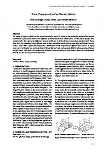
Fig. 15. Recorded module voltages with the forward topology.
disconnect the low-voltage module while continuing to provide equalization for the rest of the stack. A simple protection scheme for the above-mentioned failure mode can be implemented using fuses in series with each of the secondary windings, as shown earlier in Fig. 3. If a module voltage falls below a certain threshold, the controller action will be such that the fuse of its corresponding winding is cleared. This can be achieved by raising the input voltage so as to cause a current higher than the fuse rating. Once the fuse clears, the failed module is disconnected from the equalizer and charge equalization can proceed for the rest of the stack. The main control unit would then inform the user about the faulty modules so they can be repaired or replaced. VI. EXPERIMENTAL VERIFICATION In order to verify the concepts presented in this paper, two 100-W prototype charge equalization converters using the Forward and Flyback topologies were built in the laboratory. For the Forward Converter implementation, a three-winding coaxial winding transformer was built in the laboratory. The operating frequency was selected to be 50 kHz. The 4 : 4 coaxial windings were constructed using an AWG-14 round litz wire threaded through an AWG-14 braided litz. The selected core was an E55-3C85 from Phillips. The resultant and the transformer leakage inductances for each winding were measured to be magnetizing inductance H nH
nH nH.
Three Titan 12-V deep cycle gel-cell batteries from Exide were used in series. Their full charge voltage was 13.6 V, and they can be discharged down to 9.5 V. These modules were charged/discharged individually to have different initial states of charge. The initial value of the battery voltages were 12.37, 13.07, and 13.39, from top to bottom, respectively. The charge equalization converter was enabled for 3.5 h, and the individual cell voltages were recorded every 6 min. The resulting cell voltages were plotted, as shown in Fig. 15. It is clear from this figure that the individual cells charge to the same nominal value at the end of the charge equalization mode.
34
IEEE TRANSACTIONS ON INDUSTRY APPLICATIONS, VOL. 35, NO. 1, JANUARY/FEBRUARY 1999
(a) (a)
(b) Fig. 18. (a) Secondary charging currents at t = 0 (Current: 2 A/div, time: 5 �s/div). (b) Secondary charging currents at t = 3:5 h (Current: 2 A/div, time: 5 �s/div). (b) Fig. 16. (a) Secondary charging currents at t = 0 (Current scale: 2 A/div, time: 5 �s/div). (b) Secondary charging currents at t = 3:5 h (Current scale: 2 A/div, time: 5 �s/div).
The secondary current waveforms at the beginning and end of charge equalization are shown in Fig. 18(a) and (b), respectively. As in the previous case, the individual cells charge to the same nominal value at the end of the charge equalization mode. However, with the Flyback implementation, the charge cannot be directed to the weakest cell due to the secondaryto-secondary coupling. VII. CONCLUSIONS
Fig. 17.
Recorded module voltages with the Flyback topology.
The secondary current waveforms at the beginning and end of charge equalization are shown in Fig. 16(a) and (b), respectively. Note here that the weakest cell draws more current than the other cells [Fig. 16(a)]. As that cell charges, the charging current decreases, as shown in Fig. 16(b). For the Flyback implementation, a 3 : 1 : 1 : 1 conventional foil wound transformer was built for this purpose. The switching frequency was chosen to be 50 kHz and the duty cycle of the transistor was set to 45% to guarantee the reset of the magnetizing energy. The same battery modules were used with the same initial state of charge. The charge equalization converter was enabled for 2 h, and the individual cell voltages were recorded every 6 min. The resulting cell voltages were plotted, as shown in Fig. 17.
In this paper, design considerations for charge equalization of an EV battery system were discussed. The proposed scheme utilizes a simple isolated dc-to-dc converter with a multiwinding transformer. The proposed scheme provides a simple converter topology serving both trickle charging and charge equalization functions. It utilizes transformers with highly symmetrical transfer characteristics (CWT). In addition, it utilizes the sensing wires for monitoring and charge equalization. The proposed scheme offers a low-cost implementation and improved battery stack life. REFERENCES [1] N. H. Kutkut, D. M. Divan, and D. W. Novotny, “Charge equalization for series connected battery strings,” in Conf. Rec. IEEE-IAS Annu. Meeting, Oct. 1994, pp. 1008–1015. [2] C. C. Chan, W. S. Leung, and K. C. Chu, “A Microprocessor based intelligent charger for electric vehicle lead acid batteries,” in Proc. Electric Vehicle Symp., Hong Kong, 1990, vol. EVS-10, pp. 456–466. [3] Y. Podrazhansky and P. W. Popp, “Rapid battery charger, discharger and conditioner,” U.S. Patent 4 829 225, May 9, 1989. [4] B. Lindemark, “Individual cell voltage equalizers (ICE) for reliable battery performance,” in Conf. Rec. INTELEC, Kyoto, Japan, 1991, pp. 196–201. [5] S. T. Tung, D. C. Hopkins, and C. R. Mosling, “Extension of battery life via charge equalization,” IEEE Trans. Ind. Electron., vol. 40, pp. 96–104, Feb. 1993. [6] M. S. Rauls, D. W. Novotny, and D. M. Divan, “Design considerations for high frequency coaxial winding transformers,” IEEE Trans. Ind. Applicat., vol. 29, pp. 375–381, Mar./Apr. 1993.
KUTKUT et al.: CHARGE EQUALIZATION OF AN ELECTRIC VEHICLE BATTERY SYSTEM
[7] M. S. Rauls, D. W. Novotny, D. M. Divan, R. Bacon, and R. W. Gascoigne, “Multi-turn high frequency coaxial winding power transformers,” in Conf. Rec. IEEE-IAS Annu. Meeting, Oct. 1992, pp. 1453–1457. [8] L. F. Blume, Transformer Engineering. New York: Wiley, 1938. [9] MIT Staff, Magnetic Circuits and Transformers. New York: Wiley, 1943. [10] N. H. Kutkut, D. M. Divan, D. W. Novotny, and H. L. Wiegman, “Battery charging using a transformer with a single primary winding and plural secondary windings,” U.S. Patent 5 659 237, Aug. 19, 1997.
Nasser H. Kutkut (S’90–M’90) ) received the B.Sc. degree in electrical engineering from Jordan University of Science and Technology, Irbid, Jordan, in 1989, the M.Sc. degree in electrical engineering and computer science from the University of Illinois, Chicago, in 1990, and the Ph.D. degree in electrical engineering from the University of Wisconsin, Madison, in 1995. Between 1995 and 1998, he was a Senior Scientist with Soft Switching Technologies Corporation, Middleton, WI, where he was involved in the design and development of power electronic apparatus and systems. He is the founder and current CEO of Power Designers, LLC, Middleton WI, a power electronics design and consulting company. His main research interests include soft-switching converter topologies, high-power converters, and highfrequency magnetics design, in addition to electric vehicle battery charging and equalization. Dr. Kutkut is a member of the IEEE Industry Applications (IAS) and Power Electronics Societies, Sigma Xi, New York Academy of Science, and American Association for the Advancement of Science. He won the Second Prize Paper Award of the Industrial Power Converter Committee of the IAS in 1994.
Herman L. N. Wiegman was born in New Hampshire in 1966. He received the B.S. degree from Worcester Polytechnic Institute, Worcester, MA, in 1988 and the M.S. degree in power electronics and electric machines in 1991 from the University of Wisconsin, Madison, where he is currently working towards the Ph.D. degree. Following receipt of the M.S. degree, he joined General Electric’s Corporate Research and Development Center, Schenectady, NY, where he was responsible for developing custom power supply solutions and transitioning them to the General Electric businesses and other international firms. In 1996, he received a Netherlands–America Foundation Fellowship, administered in close association with the Fulbright Commitee, and spent one year at the Technical University of Eindhoven, The Netherlands. His major interest is the development of high fuel economy, low-emission hybrid electric vehicles (HEV’s). He and the student-run HEV team at the University of Wisconsin, Madison, have had great success developing both series and parallel hybrid vehicles. His doctoral research focuses on applying an on-line electrothermal model to predict the bidirectional power capability of power buffering batteries.
35
Deepak M. Divan (S’78–M’78–SM’91–F’98) received the B.Tech. degree from the Indian Institute of Technology, Kanpur, India, in 1975 and the M.S. and Ph.D. degrees from the University of Calgary, Calgary, Alta., Canada, in 1979 and 1983, respectively, all in electrical engineering. He has been a Professor at the University of Wisconsin, Madison, since 1985 and is an Associate Director of the Wisconsin Electric Machines and Power Electronics Consortium (WEMPEC). He is presently on leave from the university and is President and CEO of Soft Switching Technologies Corporation, Middleton, WI, a manufacturer of power conversion equipment based in He is the holder of 20 issued and pending patents and has authored over 90 technical publications, including several prize papers.
Donald W. Novotny (M’62–SM’77–F’87) received the B.S. and M.S. degrees in electrical engineering from Illinois Institute of Technology, Chicago, in 1956 and 1957, respectively, and the Ph.D. degree from the University of Wisconsin, Madison, in 1961. Since 1961, he has been a member of the faculty of the University of Wisconsin, Madison, where he is currently Grainger Professor of Power Electronics and Co-director of the Wisconsin Electric Machines and Power Electronics Consortium (WEMPEC), an educational and research support organization with over 50 industry sponsors. He served as Chairman of the Electrical and Computer Engineering Department from 1976 to 1980 and as an Associate Director of the University–Industry Research Program from 1972 to 1974 and from 1980 to 1993. He has been an active consultant to many organizations and has also been a Visiting Professor at Montana State University, the Technical University of Eindhoven, Eindhoven, The Netherlands, the Catholic University of Leuven, Leuven, Belgium, and a Fulbright Lecturer at the University of Ghent, Ghent, Belgium. He has authored more than 100 published technical articles on electric machines, variable-frequency drives, and power electronic control of industrial systems. Dr. Novotny is the winner of nine Prize Paper Awards from the IEEE Industry Applications Society. He is a member of the American Society for Engineering Education, Sigma Xi, Eta Kappa Nu, and Tau Beta Pi and a Registered Professional Engineer in the State of Wisconsin.