and custom-built robots. Numerous factors were considered to determine the viability of the platform to perform the task of providing precise mobility to a radar ...
Design, Fabrication, and Evaluation of a Mobile Robot for Polar Environments Eric L. Akers, Hans P. Harmon, Richard S. Stansbury, and Arvin Agah Department of Electrical Engineering and Computer Science The University of Kansas, Lawrence, KS 66045 USA Abstract—This paper describes the design, fabrication, and evaluation of a mobile robot as part of a radar system for measuring ice characteristics in Greenland and Antarctica. The robot can survive the polar environments, navigate the terrains, is capable of carrying the necessary radar equipment while providing power, can tow an antenna, and can provide precise positioning for the bistatic synthetic aperture radar (SAR). Keywords-polar robots, mobile robots for harsh environments.
I.
INTRODUCTION
The Polar Radar for Ice Sheet Measurements (PRISM) project’s goal is to measure the characteristics of ice sheets in polar environments [6]. It has been shown that utilizing mobile robots for harsh environments can improve the effectiveness and efficiency of polar tasks [1,4,8]. This paper describes the design and implementation of a mobile robot which can survive the polar environments, can navigate the terrain, and is capable of carrying the necessary radar equipment, and towing an antenna. The construction and evaluation of the robot comprised of a number of phases: platform assessment, platform modification, actuation, winterization, virtual prototyping, sensors, and field testing. Possible base platforms assessed included cars, tracked vehicles, ATVs, snowmobiles, and custom-built robots. Numerous factors were considered to determine the viability of the platform to perform the task of providing precise mobility to a radar system. Several vehicles were analyzed for their ability to survive various environmental conditions, the ease of automation, and available space for extra equipment. A tracked, amphibious ATV was selected as the base platform [7], and a suitable body was built for it to house the radar system, communication devices, and other necessary equipment. The robot also provided power to the onboard equipment. The platform was then converted into a computer controlled robot through the use of actuators to control its movements. The winterization phase involved the thorough weatherproofing of the robot’s exteriors to handle cold temperatures, harsh winds, and blowing snow. A virtual prototype model of the robot was built in order to perform realistic simulation experiments to determine safe operating parameters for the robot. Based on the physical robot, a model was generated, and tests were performed using the model to determine how well it performs basic tasks such as pulling the antenna while turning and what slopes the robot can climb. In order to equip the polar robot with the ability to sense its surroundings and its own internal conditions, sensor modalities were tested for operation on ice sheets to ensure that the robot This work was supported by the National Science Foundation (grant #OPP-0122520), the National Aeronautics and Space Administration (grants #NAG5-12659 and NAG5-12980), the Kansas Technology Enterprise Corporation, and the University of Kansas.
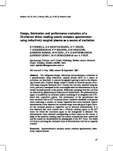
has the required reliability and precision. In order to reduce complexity, the sensor selection was directed toward commercial off-the-shelf systems. The robot was equipped with a variety of sensory modalities which includes laser range finder, gyroscope, GPS, temperature sensor, camera, and weather station. The robot was tested extensively in local parks, and was deployed and successfully tested in Greenland. The goal is to utilize the robot to operate in both Greenland and Antarctica with limited supervision (refueling and remote monitoring). A picture of the robot deployed in Greenland as part of a field experiment is shown in Figure 1.
Figure 1. Field testing of the mobile robot in Greenland.
II.
SESNORS
A suite of sensors [2] were selected to integrate with the robot, based on three categories of requirements: tasks, environmental, and proprioception (internal sensing). The sensor selection criteria included cost, power consumption, size, weight, ruggedness, accuracy and reliability. After evaluating potential sensors, the following sensors were selected: Topcon’s Legacy-E RTK GPS System for Global Positioning, LMS221 Laser Range Finder from the Sick Corporation, TCM2-50 from Precise Navigation Inc. for Tilt and Temperature Sensor, Rainwise WS-2000 Weather Station, and Pelco Esprit pan/tilt/zoom camera. The hardware and software integration of these sensors is discussed in this section. The hardware integration involves the actual mounting and placement of each sensor on and in the robot. The software integration involves the integration of the sensors via the software API that defines how the robot’s control system will interface with the sensors.
A. Hardware Integration Sensor connectivity was a major concern when selecting sensors. However, for most robotic sensors, RS-232 still remains the common method of data input/output. To facilitate the large number of RS-232 connections that are required to support all of the sensors, RocketPort RS-232 to USB hubs were used, supporting up to four RS-232 devices. In software, connections may be made to the additional com ports just as they are made to onboard RS-232 ports. A rugged laptop was selected as the robot’s brain. In terms of the physical mounting of sensors that operate outside of the vehicle’s heated enclosure, since these sensors are vulnerable to the outside climate conditions, special care must be taken so that their mounting is both appropriate and secure. The weather station was designed to be mounted on a pole so that it may be elevated above any surrounding structures. The GPS Receiver is composed of two components that reside outside of the vehicle: the GPS and radio antennas. The GPS antenna is typically mounted on a pole which is carried by an individual who is performing survey work. This pole is mounted to the rover just as the weather station was mounted. The radio antenna is identical to a typical external cell phone antenna seen and it is mounted similar to that of a car. The physical installation of the pan/tilt camera is done to obtain full visibility along the forward path. Thus, the camera is bolted to the vehicle’s roof near the center. Mounting the laser range finder requires more care since as the sensor is tilted downward, the peripheral vision of the sensor becomes diminished. This is primarily because the sensor’s scanning window is a plane and as the sensor tilts, the plane becomes more skewed and thus smaller obstacles may be overlooked along the sides. Therefore, it would be ideal to determine a position and tilt angle for the sensor on the vehicle so that the sensor provides maximum coverage with the least amount of sensor tilt. To determine this position, we first determined several key parameters. We wish to be capable of detecting obstacles before they are within 10 meters of the vehicle. We must determine a minimum obstacle height which must be detectable at 10 meters. We must also determine a maximum range in which the sensor will intersect the ground. Given these values, trigonometry may be used to determine possible heights and tilts for the sensor on the vehicle. Based on the limitations of the vehicle, the sensor’s height must be between one and two meters. The downward tilt should be less than 10 degrees. One of the several potential configurations is selected that offers the most range and the least tilt. The remaining sensors are mounted within the vehicle’s heated interior. While the GPS antennas were mounted externally, the receivers and radios are stored internally. Among the externally mounted sensors, each has power supplies that are stored within the vehicle as well. During the 2003 field season, the equipment was initially strapped down to a bookshelf like structure. However, it was concluded that this resulted in a tangle of power cords, connectors, etc. For the 2004 season, many of the sensors and sensor accessories within the vehicle are being integrated into rack mountable cases. Each of these cases has its own power supply.
B. Software Integration In this section, the software API for sensors is presented. One of the goals of developing the Software API has been to abstract the control system away from the underlying details of the physical robot. By doing so, components such as sensors or actuators may be interchanged without disrupting the overall control system. The Sensor API is part of the overall API that focuses on abstraction of sensors. To accomplish this task, a set of base sensor classes were defined. These classes represent the basic sensor types of the robot, including: bump, distance to obstacle, heading, level position, temperature, and weather. The BumpSensor interface defines the common functions that would be associated with an array of bump sensors surrounding a robot. The DistanceSensor interface supports sensors such as sonar or a laser range finder. Since each sensor outputs its values relative to its own scale (inches, centimeters, etc.), a function provides the raw integer measurements from the sensor. The HeadingSensor interface supports sensors that provide heading values. The InertiaSensor interface supports sensors that provide the current x, y, and z acceleration values. The LevelSensor interface was designed to support any sensor that monitors a level such as fuel level or battery charge. The PositionSensor interface supports sensors that determine the robot’s current position. The position is represented as a twodimensional point within a given area. The sensor can return either the X position, the Y position, or the point represented by both. The TemperatureSensor interface supports sensors that provide temperature. Temperature may be queried for Farenheight, Celcius, or both. The WeatherSensor interface defines functions for a weather station type sensor. Functions are available to query: humidity, barometric pressure, wind direction, and wind speed. Each of the interfaces above, also provide support for events and event listeners. The robot’s control system only updates state values whenever it receives events from the sensors. Thus, each sensor has its own event class, and a listener interface. Events represent changes in a sensors state. The sensor events are generated at a rate dependent on the actual sensor. A listener is an object that is listening for the event generated by the sensor. Listeners may be added or removed from each sensor’s list of listeners. Whenever an event is generated, the sensor propagates the event through its list of listeners. For each of the sensors, a brief description of its software implementation will be discussed. Primarily, each of these classes involve the parsing of data from the sensor and representing the data in a form that is specified by the above interfaces. The TopconGPSReceiver class supports the Topcon Legacy-E GPS receiver using a proprietary communication language known as the GPS Receiver Interface Language (GRIL). Using this command language, the receiver can be configured to output data strings at a rate up to 20 times per second. The Navigation Position string specified by GRIL provides all of the information that may be needed. The string includes: heading, position (in latitude and longitude), time of day, and the current receiver status (link quality, number of visible satellites, etc.). Upon receiving an update, appropriate heading and position events are produced and transmitted to the
appropriate listeners. The SickLaserRangeFinder class supports the SICK LMS221 laser range finder, providing data and events regarding the current range to obstacles. The I/O of this sensor is defined by a Datagram Specification which defines commands and data being transmitted in packets that also include header information, sensor status, and a checksum. Data from the receiver is transmitted as a single packet containing 722 bytes of data. The data may be divided into 361 high/low byte pairs representing the measured distance for each of the 361 measured points. This class provides the data as either an array of integers representing the distance in centimeters, or as an array of floats representing the distance scaled to meters. The MotionpakII class supports the MotionPak II gyroscope, it reads data and propagates update events for either of these sensor types whenever the values are updated. Each of the sensors provide two bytes of data. The unit possesses seven outputs: the x, y, and z angular rates, the x, y, z acceleration, and the unit temperature. The TCMTiltTempSensor class supports three sensors of heading, temperature, and tilt. The sensor is continually polled for data. Data is transmitted from the sensor as a NMEA 0183 string. Most of these values are quite intuitive. The WeatherStation class supports the Rainwise WS-2000, the sensor is polled twice a second to capture up-to-date weather information. The data is transmitted as a comma delimited string and upon receiving new data, events indicating a change in temperature and weather are propagated to all listening objects. The TL30FuelSensor class monitors the fuel level of a single fuel tank. If the TL30 is monitoring more than one tank, an instance of this class must be created for each tank. The class is configured so that only one of the instances will actually configure the serial communication interface. This class reads NMEA 0183 strings. Upon receiving an update, an update event is transmitted. III.
ACTUATION
The mobile platform is a skid steering driven vehicle, i.e., it is controlled by using two brakes and a throttle. The throttle controls overall speed while the brakes cause one side of the vehicle to stop, allowing it to turn in place. Actuating this platform was done by adding one actuator to control the throttle and two actuators for the control of the brakes. The linear electromagnetic motors from LinMot [3] were used and mounted in the robot. A microcontroller was used to control the motors using a LinMot controller box that received commands from an RS232 port on a PC. IV.
VIRTUAL PROTOTYPING
In order to evaluate a number of deign parameters of the rover, a virtual prototype of the rover was modeled and built using the MSC.visualNastran realistic simulation package [5]. Simulation of vehicles or components of vehicles have been used by researchers in order to design and improve vehicles models. Simulation experiments were performed to answer specific questions about the performance of the rover. Example parameters included the maximum slope the rover could climb, the placement of payload, wheeled versus the tracked options, and the towing of the antenna. Figure 2 shows the tracked and wheeled virtual prototypes of the polar robot.
Figure 2. The virtual prototypes of the polar robot (tracked and wheeled).
V.
EXPERIMENTS
During the summer of 2003, the PRISM team traveled to the North GRIP research camp (75.1 N, 42.3W) in Greenland for field experimentation. The rover survived shipping and all seals were intact, no snow accumulated inside the vehicle over a two-month period of sitting on the ice. Starting took some warming up as the vehicle battery had drained during the wait. After starting, the vehicle performed just as it had on the dirt. The next two weeks consisted of constant driving and sensor data gathering for future automation. During the driving, some of the automotive weather stripping fell off. For the most part anything that used glue or tape did not stay on, and eventually lead to snow getting inside. The snow did not affect the performance of the vehicle; it just added a little more weight when it melted. Turning in the snow was not a problem; tight turns could cause the vehicle to slowly bury itself in soft snow. Tight turns are not a problem as they also result in running over the antenna and so will be avoided. A mock antenna and rack mount computer were also added to simulate the radar. The rover had no difficulty towing the antenna on the polar terrain. During this field experiment, we were given an opportunity to validate the performance of the vehicle and its onboard equipment. Each sensor was tested thoroughly both individually and while integrated. In addition to the experiments, data collection was extensively performed while in the field. In particular, we collected data simultaneously from all sensors while approaching potential obstacles. This data will be utilized for obstacle avoidance techniques. With only a limited opportunity for field experiments, it was vital that we carefully defined the goals of our experiments: verify proper operation of all sensors in polar conditions, determine the communication link range for the GPS radio link, and examine satellite visibility and GPS accuracy in polar region. VI.
EVALUATION
In this section, the evaluation of the sensor suite is presented. For each sensor, the goals are to verify that: the sensor meets the needs of the researchers; the sensors can operate properly within polar climates and determine any potential weaknesses; the hardware and software integration of sensors within the suite are performing correctly; and sensors within the suite are viable. Validating that each sensor is capable of surviving and operating within the harsh polar environment is paramount. External sensors must be capable of surviving wind speeds up to 100 KPH and temperatures as low
as -30 degrees Celsius. While each sensor has been specified to operate within these environmental conditions, it is quite easy to confirm these specifications. During the 2003 Greenland Field Season, each sensor was tested both individually and integrated within the rover to ensure that it was operating correctly in the Artic climate. Since temperatures never dropped below -20 degrees, additional experiments were performed using a temperature chamber. During these additional experiments, the external sensors were subjected to temperatures as low as -30 degrees. Verification of the performance of the GPS System is critical to determine if the system meets the stringent needs of fellow PRISM researchers. First, the relative and absolute must be determined. The stability of these measurements are calculated. Finally, the systems performance in Greenland is determined by monitoring the number of visible satellites over a 24-hour period. In order to verify the accuracy of the GPS system, known points must be available. Relative accuracy may be determined by measuring the position of each of these points. The accuracy may be determined by comparing the measured distance between these points versus the known difference. The number of visible satellites has a major impact on the performance of RTK GPS. A minimum of five satellites must be visible to receive RTK corrections. The number of visible satellites may be reduced in Greenland because of its location above the Arctic Circle. Therefore, the number of satellites will be monitored for a 24-hour period. The results measured at Greenland are compared to measurements at the University of Kansas. The stability of the GPS measurements indicates the error bounds for the measurements. In general, plotting repeated measurements from the same location will appear within a circle surrounding the actual point. This circle represents the error bounds of the measurements. The experimental procedure to determine the measurements stability is as follows: (1) starting at one meter away from the base station, collect twenty measurements of the receiver’s position; (2) move an additional five meters away from the base station and collect 20 additional measurements; (3) repeat the above procedure for up to 100 meters; And (4) for each point, calculate the mean and standard deviation for Easting (X), Northing (Y), and Elevation (Z). In order to test the Sick LMS 221 laser range finder, a series of experiments were performed to test the configuration of the sensor’s tilt and height. Profiles of known obstacles will also be used to test the viability of the sensor within the field. The data collected while performing these experiments may also be utilized for developing a robust obstacle avoidance algorithm. In order to test the configuration of the sensor’s tilt and height, a small target was created. The target was mounted such that the height of the target may be adjusted. The values collected demonstrate the viewing window available by the laser range finder at the given designated height. The wall profile experiment was conducted, since sastrugies are a commonly encountered obstacle on ice caps, it would be convenient to collect data from the laser range finder in order to generate a profile of such an obstacle. At North GRIP, there
were not any sastrugies within the area. Therefore, a wall was erected such that we could simulate a sastrugi. While the LMS 221 is known for detecting typical above ground obstacles, little is known regarding the sensor’s ability to detected negative obstacles such as ditches, crevasses, gullies, etc. Therefore, while in Greenland, it was important to observe these obstacles using the laser range finder to determine if it may be a viable solution, or if some other mechanism is necessary. As with sastrugies, the North GRIP camp was not near any crevasses. Therefore, a snow pit was created with the dimensions 3 by 5 meters and height of 1 meter. The sensor’s default configuration was insufficient for detecting negative obstacles. Its angle of incidence with the surface was too small and the sensor would easily overlook the pit. Therefore, the sensor was raised to its maximum height and tilted downward to a point 15 meters in front of the vehicle. VII. CONCLUSION Currently the mobile robot is capable of waypoint navigation in an obstacle-free environment, i.e., the robot can move to locations as designated by their coordinates. These coordinates will be determined by the radar system as part of the required mapping. This function will be tested in the upcoming field experiments in Greenland. We have also begun work on autonomous obstacle detection in order to enable the robot to move and navigate in areas with obstacles. These issues will be addressed as part of the transition of the vehicle from a remotely operated robot to a semi-autonomous robot. Crevasse detection is a common concern for anyone operating in the polar region. Often researchers are not placed in a crevasse laden area without either a detailed map of their location, or some sort of crevasse detector. RADARSAT and prior traversals can often provide detailed information regarding the location of potential crevasses. However, it may be advantageous to acquire a ground penetrating radar for crevasse detection. Such issues will be further investigated. REFERENCES [1]
[2] [3] [4]
[5] [6] [7] [8]
Apostolopoulos, D., Wagner, M.D., Shamah, B., Pedersen, L., Shillcutt, K., and Whittaker, W.L. (2000). Technology and Field Demonstration of Robotic Search for Antarctic Meteorites. International Journal of Robotics Research. Everett, H.R. (1995). Sensors for Mobile Robots: Theory and Application. AK Peters, Massachusetts. LinMot. (2004). LinMot Motors. http://www.linmot.com. Moorehead, S., Simmons, R., Apostolopoulos, D., and Whittaker, W.L. (1999). Autonomous Navigation Field Results of a Planetary Analog Robot in Antarctica. International Symposium on Artificial Intelligence, Robotics and Automation in Space. MSC Software. (2004). MSC.visualNastran Desktop Tutorial Guide. http://www.mscsoftware.com. PRISM. (2004). Polar Radar for Ice Sheet Measurements. http://www.ku-prism.org. Recreatives Industries. (2004). Max All Terrain Vehicles. http://www.maxatvs.com. Wettergreen, D., Thorpe, C., and Whittaker W.L. (1993). Exploring Mount Erebus by Walking Robot. Robotics and Autonomous Systems, 1993.