revision of the Second Edition, extending the scope to include cold worked ...
Design manual for structural stainless steel, which was prepared by The Steel .....
For example, for an I-section a bending moment acting in the plane of the web.
Design Manual For Structural Stainless Steel (Third Edition)
2006 Euro Inox and The Steel Construction Institute ISBN 2-87997-204-3 (Second edition 2002: ISBN 2-87997-037-7) Euro Inox and The Steel Construction Institute have made every effort to ensure that the information presented here is technically correct. However, the reader is advised that the material contained therein is for general information purposes only. Euro Inox, The Steel Construction Institute and any other contributor specifically disclaim any liability or responsibility for loss, damage or injury, resulting from the use of the information contained in this publication. CD-ROM, 7 languages
ISBN 2-87997-187-X
Finnish version
ISBN 2-87997-208-6
French version
ISBN 2-87997-205-1
German version
ISBN 2-87997-210-8
Italian version
ISBN 2-87997-206-X
Spanish version
ISBN 2-87997-207-8
Swedish version
ISBN 2-87997-209-4
ii
PREFACE Third Edition This Third Edition of the Design Manual has been prepared by The Steel Construction Institute as a deliverable of the RFCS Project - Valorisation Project – Structural design of cold worked austenitic stainless steel (contract RFS2-CT-2005-00036). It is a complete revision of the Second Edition, extending the scope to include cold worked austenitic stainless steels and updating all the references to draft Eurocodes. The Third Edition refers to the relevant parts of EN 1990, EN 1991 and EN 1993. The structural fire design approach in Section 7 has been updated and new sections on the durability of stainless steel in soil and life cycle costing have been added. Three new design examples have been included to demonstrate the appropriate use of cold worked stainless steel. They were completed by the following partners: •
Universitat Politècnica de Catalunya (UPC)
•
The Swedish Institute of Steel Construction (SBI)
•
Technical Research Centre of Finland (VTT)
A project steering committee, including representatives from each partner and sponsoring organisation, oversaw the work and contributed to the development of the Design Manual. The following organizations participated in the preparation of the Third Edition: •
The Steel Construction Institute (SCI)
•
Centro Sviluppo Materiali (CSM)
•
CUST, Blaise Pascal University
•
Euro Inox
•
RWTH Aachen, Institute of Steel Construction
•
VTT Technical Research Centre of Finland
•
The Swedish Institute of Steel Construction (SBI)
•
Universitat Politècnica de Catalunya (UPC)
(Project co-ordinator)
Preface to the Second Edition This Design Manual has been prepared by The Steel Construction Institute as a deliverable of the ECSC funded project, Valorisation Project – Development of the use of stainless steel in construction (contract 7215-PP-056). It is a complete revision of the Design manual for structural stainless steel, which was prepared by The Steel Construction Institute between 1989 and 1992 and published by Euro Inox in 1994. This new edition takes into account advances in understanding in the structural behaviour of stainless steel over the last 10 years. In particular, it includes the new design recommendations from the recently completed ECSC funded project, Development of the use of stainless steel in construction (contract 7210-SA/842), which has led to the scope of the Manual being extended to cover circular hollow sections and fire resistant design. Over the last ten years a great many new European standards have been issued covering iii
stainless steel material, fasteners, fabrication, erection, welding etc. The Manual has been updated to make reference to current standards and data in these standards. A project steering committee, including representatives from each partner, sub-contractor and sponsoring organisation, oversaw the work and contributed to the development of the Manual. The worked examples were completed by the following partners: •
Centre Technique Industriel de la Construction Métallique (CTICM)
•
Luleå Institute of Technology
•
RWTH Aachen
•
VTT Technical Research Centre of Finland
•
The Steel Construction Institute (SCI)
The following people were members of the steering committee and/or completed the design examples: Nancy Baddoo
The Steel Construction Institute
Massimo Barteri
Centro Sviluppo Materiali (CSM)
Bassam Burgan
The Steel Construction Institute
Helena Burstrand Knutsson
The Swedish Institute of Steel Construction (SBI)
Lars Hamrebjörk
The Swedish Institute of Steel Construction (SBI)
Jouko Kouhi
VTT Technical Research Centre of Finland
Roland Martland
Health and Safety Executive (UK)
Enrique Mirambell
Universitat Politècnica de Catalunya (UPC)
Anders Olsson
AvestaPolarit AB (formerly, Luleå Inst. of Technology)
Thomas Pauly
Euro Inox
Esther Real
Universitat Politècnica de Catalunya (UPC)
Ivor Ryan
Centre Technique Industriel de la Construction Métallique
Heiko Stangenberg
RWTH Aachen Institute of Steel Construction
Asko Talja
VTT Technical Research Centre of Finland
ACKNOWLEDGEMENTS The following organisations provided financial support for this edition of the Design Manual and their assistance is gratefully acknowledged: •
Research Fund for Coal and Steel (RFCS) (formerly, European Coal and Steel Community (ECSC))
•
Euro Inox
The contribution made to this and the previous two editions by the European stainless steel producers and other organisations is also gratefully acknowledged. iv
FOREWORD This Design Manual has been prepared for the guidance of engineers experienced in the design of carbon steel structural steelwork though not necessarily in stainless steel structures. It is not in any way intended to have a legal status or absolve the engineer of responsibility to ensure that a safe and functional structure results. The Manual is divided into two parts: •
Part I
-
Recommendations
•
Part II
-
Design Examples
The Recommendations in Part I are formulated in terms of limit state philosophy and, where appropriate, are in compliance with the following Parts of Eurocode 3 Design of steel structures: EN 1993-1-1
Design of steel structures: General rules and rules for buildings
EN 1993-1-2
Design of steel structures: Structural fire design
EN 1993-1-3
Design of steel structures: General rules: Supplementary rules for cold-formed members and sheeting
EN 1993-1-4
Design of steel structures: General rules: Supplementary rules for stainless steels
EN 1993-1-5
Design of steel structures: Plated structural elements
EN 1993-1-8
Design of steel structures: Design of joints
EN 1993-1-9
Design of steel structures: Fatigue
EN 1993-1-10 Design of steel structures: Material toughness and through-thickness properties This Design Manual gives recommended values for certain factors. These values may be subject to modification at a national level by the National Annexes. The Design Examples contained in Part II demonstrate the use of the recommendations. A cross-reference system locates that section of the examples corresponding to a particular recommendation. The Recommendations and Design Examples are available online at Steelbiz, an SCI technical information system (www.steelbiz.org), and from the Euro Inox web site (www.euro-inox.org). A Commentary to the Recommendations, which includes a full set of references, is also available online at these web sites. The purpose of the Commentary is to allow the designer to assess the basis of the recommendations and to facilitate the development of revisions as and when new data become available. Opportunity is taken to present the results of various test programmes conducted specifically to provide background data for the Design Manual. The Recommendations, Design Examples and Commentary are also available on CD from Euro Inox.
v
An online design facility is available at www.steel-stainless.org/software for designing cold-formed stainless steel members subject to axial tension, bending or axial compression. The design facility calculates section properties and member resistances in accordance with the Recommendations in this Design Manual. The design recommendations presented in this document are based upon the best knowledge available at the time of publication. However, no responsibility of any kind for injury, death, loss, damage or delay, however caused, resulting from the use of the recommendations can be accepted by the project partners or others associated with its preparation.
vi
Contents Page No. PREFACE
iii
ACKNOWLEDGEMENTS
iii
FOREWORD
v
PART I – RECOMMENDATIONS 1
INTRODUCTION 1.1 Scope 1.2 Symbols 1.3 Conventions for member axes 1.4 Units
1 1 1 3 4
2
BASIS OF DESIGN 2.1 General requirements 2.2 Limit state design 2.3 Loading
5 5 5 7
3
MATERIALS: PROPERTIES, SELECTION AND DURABILITY 3.1 Material grades 3.2 Mechanical behaviour and design values of properties 3.3 Physical properties 3.4 Effects of temperature 3.5 Life cycle costing 3.6 Selection of materials 3.7 Durability
11 11 16 21 21 22 23 25
4
PROPERTIES OF SECTIONS 4.1 General 4.2 Maximum width-to-thickness ratios 4.3 Classification of cross-sections 4.4 Effective widths 4.5 Stiffened elements 4.6 Calculation of section properties 4.7 Resistances of cross-sections
34 34 34 34 38 43 46 49
5
MEMBER DESIGN 5.1 Introduction 5.2 Tension members 5.3 Compression members 5.4 Flexural members 5.5 Members subject to combinations of axial load and bending moments
54 54 54 54 58
JOINT DESIGN 6.1 General recommendations 6.2 Bolted connections
71 71 73
6
vii
68
6.3 6.4
Mechanical fasteners for thin gauge material Welded connections
78 78
7
DESIGN FOR FIRE RESISTANCE 7.1 General 7.2 Mechanical properties at elevated temperatures 7.3 Thermal properties at elevated temperatures 7.4 Determination of structural fire resistance
82 82 82 85 86
8
FATIGUE
94
9
TESTING 9.1 General 9.2 Stress-strain curve determination 9.3 Tests on members
95 95 95 95
10
FABRICATION ASPECTS 10.1 Introduction 10.2 Storage and handling 10.3 Shaping operations 10.4 Welding 10.5 Galling and seizure 10.6 Finishing
97 97 98 98 100 104 105
APPENDIX A
Correlation between stainless steel designations
107
APPENDIX B
Lateral-torsional buckling
109
APPENDIX C
Material data for deflection calculations
113
PART II – DESIGN EXAMPLES Design example 1
117
Design example 2
119
Design example 3
123
Design example 4
131
Design example 5
135
Design example 6
143
Design example 7
149
Design example 8
155
Design example 9
161
Design example 10
169
Design example 11
177
Design example 12
183
Design example 13
191
viii
PART 1 - RECOMMENDATIONS 1
INTRODUCTION
1.1
Scope
The recommendations given in this part of the Design Manual apply to the grades of stainless steel that are typically used in structural applications. The recommendations are intended primarily for the design of elements and secondary structural components of buildings, offshore installations and similar structures. They should not be applied to special structures such as those in nuclear installations or pressure vessels for which specific standards for stainless steel application already exist. The recommendations concern aspects of material behaviour, the design of cold formed and welded members, and their connections. They are applicable to the austenitic and duplex grades of stainless steel that are typically used in structural or architectural applications. The recommendations have been formulated using limit state philosophy.
1.2
Symbols
In general, the symbols used in this Design Manual are the same as used in EN 1993-1-1: Eurocode 3, Design of steel structures: General rules and rules for buildings. Extensive use is made of subscripts, e.g. Nb,z,Rd is the design resistance (subscript Rd) of a column under axial load (N) to buckling (subscript b) about the minor axis (subscript z). Dimensions and axes of sections are illustrated in Figure 1.1. Note that contrary to normal practice in many countries, the major axis of a section is normally y-y and the minor axis z-z, see Section 1.3. Latin upper case letters A C E F G I L M N Q R V W
Accidental action; Area Fixed value; Factor Modulus of elasticity; Effect of actions Action; Force Permanent action; Shear modulus Second moment of area Length; Span; System length Bending moment Axial force Variable action Resistance Shear force Section modulus
1
Greek upper case letters ∆
Difference in ........ (precedes main symbol)
Latin lower case letters a Distance between stiffeners; Throat thickness of a weld b Width; Breadth c Distance; Outstand d Diameter; Depth e Eccentricity; Shift of neutral axis; Edge distance; End distance f Strength (of a material) g Gap h Height i Radius of gyration; Integer k Coefficient; Factor l Buckling length m Constant n Number of ... p Pitch; Spacing q Distributed force r Radius; Root radius s Staggered pitch t Thickness uu Major axis vv Minor axis w Curling deformation xx, yy, zz Rectangular axes Greek lower case letters
α β γ
(alpha) (beta) (gamma)
Ratio; Factor Ratio; Factor Partial factor
ε
(epsilon)
235 E Strain; Coefficient = 210000 f y
λ
(lambda)
ρ σ τ ϕ χ ψ
(rho) (sigma) (tau) (phi) (chi) (psi)
0,5
Slenderness ratio (a bar above indicates non dimensional) Reduction factor Normal stress Shear stress Ratio Reduction factor (for buckling) Stress ratio; Reduction factor
Subscripts
a b c cr
Average Bearing; Buckling; Bolt Cross section Critical 2
d E eff e el f g i,j,k k LT M N net o pl R r S s t u V v w x y z σ τ
1.3
Design Euler; Internal force; Internal moment Effective Effective (with further subscript) Elastic Flange Gross Indices (replace by numeral) Characteristic Lateral-torsional (Allowing for) bending moment (Allowing for) axial force Net Initial Plastic Resistance Reduced value Secant Tensile stress (area); Stiffener Tension; Tensile; Torsion Major axis of cross-section; Ultimate (Allowing for) shear force Shear; Minor axis of cross-section Web; Weld; Warping Axis along member Yield (proof value); Axis of cross-section (major axis except for unsymmetric sections) Axis of cross-section (minor axis except for unsymmetric sections) Normal stress Shear stress.
Conventions for member axes
In general, the convention for member axes is: xx
along the length of the member.
yy
cross-section axis perpendicular to web, or the larger leg in the case of angle sections.
zz
cross-section axis parallel to web, or the larger leg in the case of angle sections.
The yy axis will normally be the major axis of the section and the zz axis will normally be the minor axis. For angle sections, the major and minor axes (uu and vv) are inclined to the yy and zz axes, see Figure 1.1. The convention used for subscripts which indicate axes for moments is: “Use the axis about which the moment acts”. For example, for an I-section a bending moment acting in the plane of the web is denoted My because it acts about the cross-section axis perpendicular to the web. 3
1.4
Units
For calculations, the following units are recommended: •
forces and loads
kN, kN/m, kN/m2
•
unit mass
kg/m3
•
unit weight
kN/m3
•
stresses and strengths
N/mm2 (= MN/m2 or MPa)
•
bending moments
kNm.
Note that, in accordance with European practice, a “,” symbol is used to separate the integer part from the decimal part in a number. b
z
z b
tw hw d y
h
y
y
d
y
tf
t
z z
z z v
t r h y
y
h
u y
y
t
u z v b
z b
Figure 1.1
Dimensions and axes of sections
4
2
BASIS OF DESIGN
2.1
General requirements
A structure should be designed and fabricated so that it can: •
remain fit for use during its intended life
•
sustain the loads which may occur during construction, installation and usage
•
localise damage due to accidental overloads
•
have adequate durability in relation to maintenance costs.
The above requirements can be satisfied by using suitable materials, by appropriate design and detailing and by specifying quality control procedures for construction and maintenance. Structures should be designed by considering all relevant limit states.
2.2
Limit state design
Limit states are limiting conditions which, when exceeded, make the structure unable to meet design performance criteria. Three classes of limit states are recognised: ultimate limit states, serviceability limit states and durability limit states. Ultimate limit states are those which, if exceeded, can lead to collapse of part or the whole of the structure, endangering the safety of people. Serviceability limit states correspond to states beyond which specified service criteria are no longer met. Durability limit states can be regarded as subsets of the ultimate and serviceability limit states depending on whether, for example, the corrosion affects the strength of the structure or its aesthetic appearance. Examples of these limit states are given below: Ultimate Limit State •
Strength (including general yielding, rupture, buckling and transformation into a mechanism)
•
Stability against over-turning and sway
•
Fracture due to fatigue
Serviceability Limit State •
Deflection
•
Vibration (e.g. wind induced)
•
Repairable damage due to fatigue
•
Creep
Durability Limit State •
Corrosion
•
Metallurgical stability
5
Ultimate limit states
For ultimate limit states, relationships of the following form have to be satisfied: Ed ≤ Rd
(2.1)
where: Ed
is the design value of the effect of actions such as an internal moment or vector in the member or element under consideration due to the factored applied loading (see Section 2.3) acting on the structure, and
Rd
is the corresponding design resistance, as given in the appropriate clause in these recommendations.
The design resistance, Rd, is generally given as Rk/γM where Rk is a characteristic resistance and γM is a partial factor. The partial factor γM takes on various values. Table 2.1 gives the γM values to be used with this Design Manual which are taken from EN 1993-1-4 and EN 1993-1-8. Reference should also be made to the National Annex (NA) to EN 1993-1-4 and other relevant parts of EN 1993 for the country for which the structure is being designed because modified values for γM may be given that should be used instead of the values given in Table 2.1. (If a NA is not available, then γM factors should be agreed with the relevant national regulator.) As an alternative to analysis, the design resistance may be assessed by testing of materials, components and structures (for guidance see Section 9). Table 2.1
Recommended values of γM
For resistance of:
Symbol
Value (EN 1993-1-4)
Cross-sections to excessive yielding including buckling
γM0
1,10
Members to instability assessed by member checks
γM1
1,10
Cross-sections in tension to fracture
γM2
1,25
Bolts, welds, pins and plates in bearing
γM2
1,25
For resistance of:
Symbol
Value (EN 1993-1-8)
Joints in hollow section lattice girder
γM5
1,00
Pins at the serviceability limit state
γM6,ser
1,00
Serviceability limit states
The corresponding relationship for serviceability limit states is: Ed ≤ Cd
(2.2)
where: Ed
is the design value of the effects of actions specified in the serviceability criterion e.g. member deflection response to forces and
6
moments in the member due to the unfactored applied loading (Fk, see Section 2.3.4), and Cd
is the limiting design value of the relevant serviceability criterion.
Durability limit states
These states require consideration of the corrosion phenomena addressed in Section 3.7.
2.3
Loading
2.3.1 General In the Eurocodes, loading is expressed terms of ‘actions’. defined as:
An ‘action’ is
•
A set of forces (loads) applied to the structure (direct action)
•
A set of imposed deformations or accelerations caused by, for example temperature changes, moisture variation, uneven settlement or earthquakes (indirect action).
Characteristic values (Fk) of individual actions are specified: •
in EN 1991 Actions on structures (taking into account possible additions and/or changes in the relevant National Annex) or other relevant loading code, or
•
by the client, or the designer in consultation with the client, provided that the minimum provisions specified in the relevant loading codes or by a competent authority are observed.
The design values of individual actions (Fd) are given by multiplying characteristic actions by partial factors for actions (γF). The design case is established by considering all realistic combinations of actions and identifying the critical case.
2.3.2 Ultimate limit state - Onshore factored loads The following types of action are recognised: •
“Permanent” actions (G) - e.g. self-weight of structures, fittings, ancillaries and fixed equipment.
•
“Variable” actions (Q) - e.g. imposed loads, wind loads, snow loads, and thermal loads.
•
“Accidental” actions (A) - e.g. explosions, fire and vehicle impact.
EN 1990 Basis of Structural Design gives combinations of actions for use in design of buildings and recommended values for partial factors for actions (γF). Reference should also be made to the National Annex to EN 1990 for the country for which the structure is being designed because it may give modified values for γF that should be used instead of the recommended values. The NA also gives recommended values for the combination factors (ψ factors) and the unfavourable permanent actions (ξ factors). (If a NA is not available, then γF,
ψ and ξ factors should be agreed with the relevant national regulator.) 7
Reference should be made to the National Annex of EN 1991 regarding numerical values for loads. As given in EN 1990, for normal usage, i.e. in situations not involving accidents, the combination of actions may be expressed as:
∑ γ G, j Gk, j j ≥1
∑ γ Q,iψ 0,iQk,i
+ γ Q,1 Q k,1 +
(2.3)
i >1
or alternatively, the less favourable of the following expressions
∑ γ G, j Gk, j j ≥1
+ γ Q,1ψ 0,1Qk,1 +
∑ ξ jγ G, j Gk, j j ≥1
+ γ Q,1 Q k,1 +
∑ γ Q,i ψ 0,iQk,i
(2.4a)
i >1
∑ γ Q,i ψ 0,iQk,i
(2.4b)
i >1
where: Gk,j
is the characteristic value of the permanent action
Qk,1
is the characteristic value of leading variable action 1 (i.e. the most unfavourable variable action)
Qk,i
are the characteristic values of the accompanying variable actions i
j
is the index for permanent action
i
is the index for variable action
γG,j
is the partial factor for the permanent action Gk,j
γQ,1
is the partial factor for the leading variable action 1
ξj
is a reduction factor for unfavourable permanent actions G
ψ0,i
is a reduction factor for combination value of a variable action Q.
However, reference again should be made to the NA for the particular country for which the structure is being designed. The following recommended values are given in EN 1990:
γG,j
= 1,35 (for unfavourable effects)
γQ,1
= 1,5
ξ
= 0,85
γQ,i
= 1,5
The value of ψ 0 depends on the type of loading (see EN 1990). Equations 2.4a and 2.4b were introduced because Equation 2.3 was unduly pessimistic for heavyweight structures. For steel structures, Equations 2.4a and 2.4b generally result in lighter loads than Equation 2.3.
2.3.3 Ultimate limit state - Offshore factored loads Reference may be made to API RP2A - LRFD Recommended Practice for Planning, Designing and Constructing Fixed Offshore Platforms - Load and Resistance Factor Design, First Edition, 1993. The following factored load combinations from AP1 RP2A for the in-place condition are suggested for use in this Design Manual in conjunction with the
8
loads specified in API RP2A for the design of topside stainless steel components. Note that the notation is as used in API RP2A. Operating conditions:
1,3D1 + 1,3D2 + 1,5L1 + 1,5L2 + 1,2(Wo + 1,25Dn)
(2.5)
Extreme storm conditions:
1,1D1 + 1,1D2 + 1,1L1 + 1,35(We + 1,25Dn)
(2.6)
When internal forces due to gravity loads oppose the internal forces due to wind, wave and current loads, the gravity loads should be reduced such that: 0,9D1 + 0,9D2 + 0,8L1 + 1,35(We + 1,25Dn)
(2.7)
where: D1
is the dead load, including self-weight of structures, fittings, ancillaries and permanent equipment
D2
is the dead load, including weight of equipment and other objects which may change from one mode of operation to another
L1
is Live load 1 (includes weight of consumable supplies in pipes and tanks)
L2
is Live load 2 (short duration forces arising from operations such as lifting of drill string, lifting by cranes, machine operations, vessel mooring and helicopter loadings)
Wo
is the operator defined operating wind, wave and current load or effects
We
are the extreme wind, wave and current load or effects (100 year return period)
Dn
are the inertial forces.
2.3.4 Serviceability limit state loads Serviceability limit states should be checked for the following combinations: •
characteristic
•
frequent
•
quasi-permanent load combinations.
EN 1990 gives combinations of actions for use in design of buildings. (Reference should also be made to the NA for the particular country for which the structure is being designed.) EN 1990 also requires that the acceptable deflection should be agreed with the client. For the characteristic combination, normally used for irreversible limit states, the following load combination should be used:
∑ Gk, j + Qk,1 + ∑ψ 0,i Qk,i j ≥1
(2.8)
i >1
where all terms are defined in Section 2.3.2.
9
Note that EN 1990 gives the appropriate combinations of actions to use in the following situations:
•
for calculating deflections under normal combinations of actions (Clause A.1.4.3(1))
•
when long term deformations due to shrinkage, relaxation or creep need to be considered (Clause A.1.4.3(6))
•
if the appearance of the structure or the comfort of the user or functioning of machinery are being considered (Clauses A.1.4.3(4) and (5)).
10
3
MATERIALS: PROPERTIES, SELECTION AND DURABILITY
3.1
Material grades
3.1.1 Introduction There are many different types of stainless steel. Not all of these are suitable for structural applications, particularly where welding is contemplated. There are five basic groups of stainless steel, classified according to their metallurgical structure: these are the austenitic, ferritic, martensitic, duplex and precipitation-hardening groups. The austenitic stainless steels and the duplex stainless steels are generally the more useful groups for structural applications. Austenitic stainless steels provide a good combination of corrosion resistance, forming and fabrication properties. Duplex stainless steels have high strength and wear resistance with very good resistance to stress corrosion cracking. The most commonly used grades, typically referred to as the standard austenitic grades, are 1.4301 (widely known as 304) and 1.4401 (widely known as 316). They contain about 17-18% chromium and 8-11% nickel. Grade 1.4301 is suitable for rural, urban and light industrial sites whilst grade 1.4401 is a more highly alloyed grade and will perform well in marine and industrial sites. The low carbon versions of these grades are 1.4307 (304L) and 1.4404 (316L). Grades 1.4301 and 1.4401 were formerly made with significantly higher carbon levels with implications for corrosion behaviour1. Either the ‘L’ grade, or a stabilised steel such as 1.4541 and 1.4571 would have been used where there was concern about corrosion performance in the as-welded condition. Grade 1.4318 is a low carbon, high nitrogen stainless steel which work hardens very rapidly when cold worked. It has a long track record of satisfactory performance in the railcar industry and is equally suitable for automotive, aircraft and architectural applications. Grade 1.4318 has similar corrosion resistance to 1.4301 and is most suitable for applications requiring higher strength than 1.4301 where large volumes are required. It is procured directly from the mill; specifiers interested in using 1.4318 should check availability directly with the mill. Its price is likely to be slightly higher than 1.4301, depending on the amount required. An increasing use of stainless steels for load bearing applications has led to a demand for ‘lean’ duplex grades in which the mechanical and corrosion properties of duplex grades are combined with a leanly alloyed chemical composition. In the forthcoming Parts 4 and 5 of EN 10088 (see Section 3.1.2), the newly developed duplex grade 1.4162 is included. Grade 1.4162 is suitable for many applications in the construction sector with a proof strength in
1
Carbon present in the steel reacts with chromium and precipitates chromium carbides on grain boundaries under certain thermal cycles, e.g. in the weld heat affected zones (HAZ). The local loss of chromium from the boundary region into the carbide particles allows preferential intercrystalline corrosion attack and the steel is said to be sensitized, or to suffer from weld decay (see Section 3.7.2). 11
the range of 450 – 530 N/mm2, a corrosion resistance between the austenitic grades 1.4301 and 1.4404 and a lean chemical composition. Only the rolled versions, as opposed to the cast versions, are considered. Guidance on grade selection for particular applications is given in Section 3.6.
3.1.2 Relevant standards Flat and long products
The relevant standard is EN 10088, Stainless steels. It comprises three parts:
•
Part 1, Lists of stainless steels, gives the chemical compositions and reference data on some physical properties such as modulus of elasticity, E.
•
Part 2, Technical delivery conditions for sheet, plate and strip of corrosion resisting steels for general purposes, gives the technical properties and chemical compositions for the materials used in forming structural sections.
•
Part 3, Technical delivery conditions for semi-finished products, bars, rods, wire, sections and bright products of corrosion resisting steels for general purposes, gives the technical properties and chemical compositions for the materials used in long products.
Parts 4 (flat products) and 5 (long products) of EN 10088 are now in preparation to cover material for construction purposes. They are likely to be published in 2007. The designation systems adopted in EN 10088 are the European steel number and a steel name. For example, grade 304L has a steel number 1.4307, where:
1.
43
07
Denotes steel
Denotes one group of stainless steels
Individual grade identification
The steel name system provides some understanding of the steel composition. The name of the steel number 1.4307 is X2CrNi18-9, where:
X
2
CrNi
18-9
Denotes high alloy steel
100 x % of carbon
Chemical symbols of main alloying elements
% of main alloying elements
Each stainless steel name has a unique corresponding steel number. Appendix A gives a table showing the designations for equivalent grades of stainless steel in various national and European standards. Table 3.1 gives minimum specified mechanical properties of common stainless steels to EN 10088-2. The chemical compositions of these grades are given in Table 3.2.
12
Both austenitic and duplex stainless steels can be assumed to be adequately tough and not susceptible to brittle fracture for service temperatures down to − 40°C. Design values of the mechanical properties are addressed in Section 3.2.4. Table 3.1
Specified mechanical properties of common stainless steels to EN 10088-2
Grade
Basic chromiumnickel austenitic steels
Molybdenumchromiumnickel austenitic steels
1.4301
1.4307
1.4401
1.4404
1.4541 Stabilised austenitic steels 1.4571 Low carbon, high nitrogen austenitic steel
1.4318
1.4362 Duplex steels 1.4462
Minimum 0.2% proof strength(2) (N/mm2)
Ultimate tensile strength (N/mm2)
Elongation after fracture (%)
8
230
540 – 750
45(3)
H
13,5
210
520 – 720
45(3)
P
75
210
520 – 720
45
C
8
220
520 –700
45
H
13,5
200
520 –700
45
P
75
200
500 – 700
45
Product form(1)
Max thickness (mm)
C
C
8
240
530 – 680
40
H
13,5
220
530 – 680
40
P
75
220
520 – 670
45
C
8
240
530 – 680
40
H
13,5
220
530 – 680
40
P
75
220
520 – 670
45
C
8
220
520 – 720
40
H
13,5
200
520 – 720
40
P
75
200
500 – 700
40
C
8
240
540 – 690
40
H
13,5
220
540 – 690
40
P
75
220
520 – 670
40
C
8
350
650 – 850
35
H
13,5
330
650 – 850
35
P
75
330
630 – 830
45
C
8
450
650 – 850
20
H
13,5
400
650 – 850
20
P
75
400
630 – 800
25
C
8
500
700 – 950
20
H
13,5
460
700 – 950
25
P
75
460
640 – 840
25
Notes: (1) C=cold rolled strip, H=hot rolled strip, P=hot rolled plate (2) Transverse properties (3) For stretcher levelled material, the minimum value is 5% lower
13
Table 3.2
Chemical composition to EN 10088-2 Content of alloying element (maximum or range permitted) weight %
Duplex steels
Austenitic steels
Grade
C
Cr
Ni
Mo
Others
1.4301
0,07
17,5 – 19,5
8,0 – 10,5
1.4307
0,03
17,5 – 19,5
8,0 – 10,5
1.4401
0,07
16,5 – 18,5
10,0 – 13,0
2,0 – 2,5
1.4404
0,03
16,5 – 18,5
10,0 – 13,0
2,0 – 2,5
1.4541
0,08
17,0 – 19,0
9,0 – 12,0
1.4571
0,08
16,5 – 18,5
10,5 – 13,5
1.4318
0,03
16,5 – 18,5
6,0 - 8,0
1.4362
0,03
22,0 – 24,0
3,5 – 5,5
0,1 – 0,6
N: 0,05 – 0,2
1.4462
0,03
21,0 – 23,0
4,5 – 6,5
2,5 – 3,5
N: 0,1 – 0,22
Ti: 5xC – 0,7 2,0 – 2,5
Ti: 5xC – 0,7
(1)
(1)
N: 0,1 – 0,2
Note: (1) Titanium is added to stabilise carbon and improve corrosion performance in the heat affected zones of welds. However, except for very heavy section construction, the use of titanium stabilised austenitic steels has been superseded largely by the ready availability of the low carbon grades, 1.4307 and 1.4404.
Bolts
Stainless steel bolts are covered by EN ISO 3506, Corrosion-resistant stainless steel fasteners. The specification gives chemical compositions and mechanical properties for fasteners in the austenitic, martensitic and ferritic groups. Alternative materials not specifically covered in the specification are permitted if they meet the physical and mechanical property requirements and have equivalent corrosion resistance. In EN ISO 3506, bolt and nut materials are classified by a letter: “A” for austenitic, “F” for ferritic and “C” for martensitic. It is recommended that austenitic bolts are used, for which the properties are as given in Tables 3.3 and 3.4 (taken from EN ISO 3506). The letter is followed by a number (1, 2, 3 4 or 5) which reflects the corrosion resistance; 1 representing the least durable and 5 the most durable. Steel grade A1 is specially designed for machining. Due to high sulfur content, the steels within this grade have lower resistance to corrosion than corresponding steels with normal sulfur content. Care should be exercised if Grade A1 bolts are being considered, see Section 3.6.1. Steels of grade A2 have equivalent corrosion resistance to grade 1.4301. Steels of grade A3 are stabilised stainless steels with equivalent corrosion resistance to grade 1.4541. (A stabilised steel is one which contains an addition of a strong carbide-forming agent such as titanium, which reacts preferentially with carbon and prevents formation of chromium carbides.) Steels of grade A4 contain molybdenum and have equivalent corrosion resistance to grade 1.4401. Steels of grade A5 are stabilised molybdenum-bearing stainless steels with properties of grade 1.4571 steel. 14
Austenitic bolts can be obtained in three ultimate strength levels (known as property classes), see Table 3.3. Note that values must be agreed for bolts larger than M39 for property class 50 and M24 for property classes 70 and 80 as the values depend on the alloy and manufacturing method. Bolts manufactured to property class 50 will be non-magnetic, but those to property classes 70 and 80 may demonstrate some magnetic properties. The condition of the alloy in property class 50 bolts is soft, resulting in the highest corrosion resistance. Property classes 70 and 80 are cold worked and this can affect corrosion resistance slightly. Property class 50 bolts having machined threads may be more prone to thread galling, see Section 10.5. Consideration should be given to matching the strength and corrosion resistance of the bolts and parent material. EN 14399 gives rules for the CE marking of bolts. Table 3.3
Minimum specified mechanical properties of austenitic grade bolts and nuts to EN ISO 3506 Bolts
Grade(1)
A1, A2, A3, A4 and A5
Property class
50
Thread diameter range
Nuts
Ultimate tensile strength(2) (N/mm2)
Stress at 0,2% permanent strain (N/mm2)
500
210
500
≤ M39
Proof load stress (N/mm2)
70
≤ M24
700
450
700
80
≤ M24
800
600
800
(3) (3)
Notes: (1) In addition to the various steel types covered in EN ISO 3506 under property class 50, 70 and 80, other steel types to EN 10088-3 may also be used. (2) The tensile stress is calculated on the stress area. (3) For fasteners with nominal thread diameters d>24 mm, the mechanical properties shall be agreed upon between user and manufacturer and marked with grade and property class according to this table.
15
Table 3.4 Grade
Chemical composition of bolts to EN ISO 3506 Chemical composition (percentage weight)
(1)
C
Cr
Ni
Mo
Si
Mn
P
S
A1
0,12
16,0 – 18,0
5,0 10,0
0,7
1,0
6,5
0,20
0,15 0,35
A2
0,1
15,0 – 20,0
8,0 – 19,0
(2)
1,0
2,0
0,05
0,03
A3
0,08
17,0 19,0
9,0 12,0
(2)
1,0
2,0
0,045
0,03
A4
0,08
16,0 18,5
10,0 15,0
2,0 3,0
1,0
2,0
0,045
0,03
A5
0,08
16,0 18,5
10,5 14,0
2,0 3,0
1,0
2,0
0,045
0,03
Others
Either Ti: ≥ 5xC – 0,8 Or Nb/Ta: ≥ 10xC – 1,0
Either Ti: ≥ 5xC – 0,8 Or Nb/Ta: ≥ 10xC – 1,0
Note: (1) Values are maxima unless indicated otherwise (2) Molybdenum may be present at the discretion of the manufacturer
3.2
Mechanical behaviour and design values of properties
3.2.1 Basic stress-strain behaviour The stress-strain behaviour of stainless steels differs from that of carbon steels in a number of respects. The most important difference is in the shape of the stress-strain curve. Whereas carbon steel typically exhibits linear elastic behaviour up to the yield stress and a plateau before strain hardening is encountered, stainless steel has a more rounded response with no well-defined yield stress (see Figure 3.1). Therefore, stainless steel “yield” strengths are generally quoted in terms of a proof strength defined for a particular offset permanent strain (conventionally the 0,2% strain), as indicated in the Figure 3.1. Note that Figure 3.1 shows typical experimental stress-strain curves. The curves shown are representative of the range of material likely to be supplied and should not be used in design. Stainless steels can absorb considerable impact without fracturing due to their excellent ductility (especially the austenitic grades) and their strain hardening characteristics.
16
σ N/mm² 600
1.4462
E
σ 0,2
1.4318
Carbon steel (grade S355)
400
σ 0,2
1.4301/1.4401
200 E
0
0,002
0,005
0,010
0,015
(σ0,2 is the 0,2% proof strength) Figure 3.1
ε
Typical stress-strain curves for stainless steel and carbon steel in the annealed condition (for longitudinal tension)
3.2.2 Factors affecting stress-strain behaviour There are factors that can change the form of the basic stress-strain curve for any given grade of stainless steel. These factors are to some extent interdependent and include: Cold working
Strength levels of austenitic and duplex grades are enhanced by cold working (such as imparted during cold forming operations including roller levelling/flattening and also during fabrication). Associated with this enhancement is a reduction in ductility but this normally is of slight consequence due to the initial high values of ductility, especially for the austenitic stainless steels. Table 3.5 gives the cold worked levels specified in EN 1993-1-4 which are taken from the European material standard for stainless steel, EN 10088. Cold worked steels may be specified either in terms of minimum 0,2% proof strength or ultimate tensile strength or hardness, but only one parameter can be specified. As stainless steel is cold worked, it tends to exhibit non-symmetry of tensile and compressive behaviour and anisotropy (different stress-strain characteristics parallel and transverse to the rolling directions). The degree of asymmetry and anisotropy depends on the grade, level of cold working and manufacturing route. Figure 3.2 shows stress-strain curves for grade 1.4318 cold worked to C850; the compression strength in the longitudinal direction lies below the tensile strength in both the transverse and longitudinal direction (the values traditionally given in material standards such as EN 10088 and reported accordingly by suppliers). Care is therefore needed in the choice of design strength for cold worked material (see Section 3.2.4). Additional information about values related to other types or directions of loading should be sought from the supplier.
17
The price of cold worked stainless steel is slightly higher than the equivalent annealed material, depending on the grade, product form and level of cold working. Cold worked strength levels in EN 10088-2 (applicable to material of thickness ≤ 6 mm)
Table 3.5 Cold worked condition
Minimum 0,2% proof strength1) 2)
CP350
350
700
3)
1.4301, 1.4541, 1.4401, 1.4571
CP500
500
850
3)
1.4301, 1.4541, 1.4401, 1.4571, 1.4318
CP700
700
1000
Minimum tensile strength1) 2)
Available steel grades in the cold worked condition
3)
1.4318, 1.4301
C700
350
3)
700
1.4301, 1.4541, 1.4401, 1.4571
C850
500
3)
850
1.4301, 1.4541, 1.4401, 1.4571, 1.4318
C1000
700
3)
1000
1.4318, 1.4301
Note: (1) Intermediate 0,2% proof strength or tensile strength values may be agreed. (2) Maximum product thickness for each strength level decreases with strength. Maximum product thickness and remaining elongation are also dependent on the work hardening behaviour of the steel and the cold working conditions more exact information may be requested from the manufacturer. (3) Not specified, indicative minimum values.
1000
σ N/mm²
800 600 400 200 0
0,005
0,010
0,015
0,020
0,025
0,030
ε
Longitudinal - tensile Longitudinal - compression Transverse - tensile Transverse - compression
Figure 3.2
Typical stress-strain curves for grade 1.4318 cold worked to strength level C850
During the fabrication of a section, a 0,2% proof strength enhancement by a factor of about 50% is typical in cold formed corners of cross sections. However, the effect is localised and the increase in member resistance is dependent on the location of the corners within the section; e.g. in a beam, little benefit would be obtained for corners close to the neutral axis. The strength enhancement easily compensates for any effect due to thinning of the material at cold worked corners. If advantage is to be made of localised increased strength arising from fabrication, this should be proved by testing (see Section 9). 18
Subsequent welding of the member will have a partial annealing effect with a consequential reduction in any enhanced strength properties arising from cold working - Section 6.4.4 gives guidance on the design of welded connections between members from cold worked material. Strain-rate sensitivity
Strain-rate sensitivity is more pronounced in stainless steels than in carbon steels. That is, a proportionally greater strength can be realised at fast strain rates for stainless steel than for carbon steel. Heat treatment
Annealing, or softening, reduces the strength enhancement and the anisotropy.
3.2.3 Typical values of properties It should be apparent from Sections 3.2.1 and 3.2.2 above that more factors are involved when considering the mechanical properties of stainless steels than for carbon steels. Their metallurgy is more complex and the manufacturing process has a higher impact on their final properties. For any given grade it is to be expected that there will be differences in properties for materials made by different manufacturers. However, the mechanical properties, being dependent on chemical composition and thermo-mechanical treatment, are therefore largely under the control of the manufacturers and it is possible to negotiate desired properties with individual manufacturers. From a structural point of view, the margin by which the actual 0,2% proof stress exceeds the minimum specified value is significant. Typical mean proof stresses lie between 20 and 35% above the specified minima. The proportions of enhancement observed for proof stresses are not shared by ultimate tensile strength values, which typically are only about 10% above specified minima.
3.2.4 Design values of properties Flat products
Three options may be considered: minimum specified values, verified material test data or mill certificate data. (i) Design using minimum specified values Annealed material Take the characteristic yield strength, fy, and the characteristic ultimate tensile strength, fu as the minimum values specified in EN 10088-2 (given in Table 3.1). Cold worked material Increased nominal values of fy and fu may be adopted for material delivered in the cold worked conditions specified in EN 10088. For material delivered to a specified 0,2% proof strength (e.g. CP350), the minimum 0,2% proof strength in Table 3.5 may be taken as the characteristic strength. To take into account asymmetry of the cold worked material in those cases where compression in the longitudinal direction is a relevant stress condition (i.e. column behaviour or bending), the characteristic value should be taken as 0.8 × 0.2% proof strength in
19
Table 3.5. A higher value may be used if supported by appropriate experimental data. For material delivered to a specified tensile strength (e.g. C700), the minimum tensile strength in Table 3.5 may be taken as the characteristic strength; the minimum 0,2% proof strength should be obtained from the supplier. Note 1: Rectangular hollow sections are available in material cold worked to intermediate strengths between CP350 and CP500 with the yield and ultimate tensile strength guaranteed by the producer (the yield strength being valid in tension and compression). Note 2: The design rules in this Design Manual are applicable for material up to grade CP500 and C850. For higher cold worked strength levels, design should be by testing according to Section 9. An exception is members with Class 1, 2 and 3 cross-sections which are not subject to local or global instability, for which the cross-section resistance may be calculated according to Section 4.
(ii)
Design using test data This should only be considered as an option where tensile testing has been carried out on coupons cut from the plate or sheet from which the members are to be formed or fabricated. The designer should also be satisfied that the tests have been carried out to a recognised standard, e.g. EN 10002-1, and that the procedures adopted by the fabricator are such that the member will be actually made from the tested material and positioned correctly within the structure. A value for the design strength can be derived from a statistical approach carried out in accordance with the recommendations in Annex D of EN 1990. It is recommended that the characteristic ultimate tensile strength, fu, should still be based on the specified minimum value given in EN 10088-2.
(iii)
Design using mill certificate data Measured values of the 0,2% proof stress are given on the mill (or release) certificate. A value for the design strength can be derived from a statistical approach carried out in accordance with the recommendations in Annex D of EN 1990. It is recommended that the characteristic ultimate tensile strength, fu, should still be based on the specified minimum value given in EN 10088-2.
A value of 200 000 N/mm2 is given by EN 10088-1 for Young’s modulus for all the standard austenitic and duplex grades typically used in structural applications. For estimating deflections, the secant modulus is more appropriate, see Section 5.4.6. For these grades, a value of 0,3 can be taken for Poisson’s ratio and 76 900 N/mm2 for the shear modulus, G. Bolts
For calculating the resistance of a bolt under tension or shear or combined tension and shear, take the basic strength fub as: 20
fub = σub where σub is the specified minimum ultimate tensile strength given in Table 3.3 for the appropriate property class. When it is necessary to consider the long term resistance of a bolt, reference should be made to EN 1990 for the appropriate combination of actions at the Ultimate Limit State.
3.3
Physical properties
Table 3.6 gives the room temperature physical properties in the annealed condition of the range of EN 10088 grades covered in this Design Manual. Physical properties may vary slightly with product form and size but such variations are usually not of critical importance to the application. Table 3.6 Grade
Room temperature physical properties, annealed condition Density (kg/m3)
Thermal expansion 20 – 1000C (10-6/0C)
Thermal conductivity (W/m0C)
Heat capacity (J/kg0C)
1.4301
7900
16
15
500
1.4307
7900
16
15
500
1.4401
8000
16
15
500
1.4404
8000
16
15
500
1.4541
7900
16
15
500
1.4571
8000
16,5
15
500
1.4318
7900
16
15
500
1.4362
7800
13
15
500
1.4462
7800
13
15
500
From a structural point of view, the most important physical property is the coefficient of linear expansion which, for the austenitic grades, differs considerably from that for carbon steel (12 x 10-6/°C). Where carbon and stainless steel are used together, the effects of differential thermal expansion should be considered in design. Duplex and ferritic grades are magnetic. Where the non-magnetic properties of the austenitic grades are important to the application, care must be exercised in selecting appropriate welding consumables to minimise the ferrite content in the weldment. Heavy cold working, particularly of the lean alloyed austenitic steel, can also increase magnetic permeability; subsequent annealing would restore the non-magnetic properties. For non-magnetic applications, it is recommended that further advice be obtained from a steel producer.
3.4
Effects of temperature
Austenitic grades are used for cryogenic applications. At the other end of the temperature scale, austenitic and duplex grades retain a higher proportion of their strength above about 550°C than carbon steel. However, the design of structures subject to long term exposure at cryogenic temperatures or to long 21
term exposure at high temperatures is outside the scope of this Design Manual. Suffice it to say that other mechanical properties and types of corrosion than those considered in this Section 3 take on a greater significance. Other stainless steels than those selected here are in most cases better suited for high temperature applications and further advice should be sought. Duplex steels should not be used for long periods at temperatures above about 300°C, due to the possibility of embrittlement. Section 7 covers fire resistant design and gives mechanical and physical properties at high temperatures.
3.5
Life cycle costing
There is increasing awareness that life cycle (or whole life) costs, not just initial costs, should be considered when selecting materials. Life cycle costs take account of:
•
initial costs,
•
operating costs,
•
residual value.
Stainless steel is sometimes considered to be an expensive material. However, experience has shown that using a corrosion resistant material in order to avoid future maintenance, downtime and replacement costs can save costs which far outweigh higher initial material costs. The initial cost of a structural stainless steel product is considerably higher than that of an equivalent carbon steel product, depending on the grade of stainless steel. However, savings will arise from the omission of surface coatings at regular (repeated) intervals in time. The excellent corrosion resistance of stainless steel can offer many benefits including:
•
reduced inspection frequency and costs,
•
reduced maintenance costs,
•
long service life.
Stainless steel has a high residual value (i.e. value at the end of a structure's life), though this is rarely a deciding factor for a structure with a long projected life (for instance over 50 years). Life cycle costing uses the standard accountancy principle of discounted cash flow to reduce all those costs to present day values. The discount rate encompasses inflation, bank interest rates, taxes and, possibly, a risk factor. This allows a realistic comparison to be made of the options available and the potential long term benefits of using stainless steel to be assessed against other material selections.
22
3.6
Selection of materials
3.6.1 Grades In the great majority of structural applications utilising stainless steel, it is the metal's corrosion resistance, which is being exploited, whether this be for reasons of aesthetics, minimal maintenance or long-term durability. Corrosion resistance must therefore be the primary factor in choosing a suitable grade. Stainless steels derive their corrosion resistance from the presence of a passive surface film which, given adequate access to oxygen or suitable oxidising agents, tends to be self-healing when damaged. This oxide film is primarily a consequence of the chromium content of the steel, though the addition of nickel and other alloying elements can substantially enhance the protection offered by the film. In particular, a small percentage of molybdenum is used to improve the pitting resistance of the steel (see Section 3.7.2). It is when the surface oxide film is damaged, possibly by electro-chemical attack or by mechanical damage, that corrosion might initiate. Careful design should ensure trouble-free performance, but designers should be aware that even stainless steels may be subject to various forms of corrosion under certain circumstances. Notwithstanding the existence of these degradation effects, it is perfectly possible to employ stainless steels extremely effectively, provided that a few elementary principles are kept in mind. It is only when these materials are used without consideration for the principles behind their corrosion properties that problems might be encountered. The selection of the correct grade of stainless steel must take into account the environment of the application, the fabrication route, surface finish and the maintenance of the structure. It might be noted that the maintenance requirement is minimal: merely washing down the stainless steel, even naturally by rain, will markedly assist in extending the service life. The first step is to characterise the service environment, including reasonably anticipated deviations from the design conditions. In categorising atmospheric environments, special attention should be given to highly localised conditions such as proximity to chimneys venting corrosive fumes. Possible future developments or change of use should also be considered. The surface condition and the temperature of the steel, and the anticipated stress, could also be important parameters (see Section 3.7.2). Candidate grades can then be chosen to give overall satisfactory corrosion resistance in the environment. The selection of a candidate steel should consider which possible forms of corrosion might be significant in the operating environment. To do this requires some appreciation of the nature of corrosion found in stainless steels. Section 3.7 outlines the broad principles underlying the corrosion of stainless steels, and indicates conditions where use of stainless steels should be free of undue risk and complication. It is also intended to illustrate general points of good practice, as well as the circumstances where stainless steels might have to be used with caution. In these latter conditions specialist advice should be sought, for in many cases the steels can still be successfully used. Consideration should then be given to mechanical properties, ease of fabrication, availability of product forms, surface finish and costs. 23
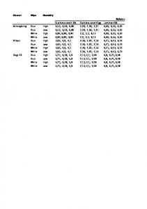
Assessing the suitability of grades is best approached by referring to experience of stainless steels in similar applications and environments. Table 3.7 gives guidance for selecting suitable grades for atmospheric environments. National regulations should also be checked, since in some cases they may be more onerous. In the case of immersed stainless steel, see Section 3.7.3. When stainless steel comes into contact with chemicals, expert advice should always be sought. Caution should be exercised when considering the use of free-machining stainless steels for fasteners. The addition of sulfur in the composition of these steels in the austenitic class renders them more liable to corrosion, especially in industrial and marine environments. In particular, this applies to fasteners in EN ISO 3506 grade A1 materials, see Table 3.3. Table 3.7
Suggested grades for atmospheric applications Location
Steel grade
Rural
Urban
Industrial
L
M
H
L
M
H
L
Basic chromium-nickel austenitic steels (e.g. 1.4301, 1.4307, 1.4541, 1.4318)
T
T
T
T
T
Molybdenum-chromium-nickel austenitic steels (e.g. 1.4401, 1.4404, 1.4571) and duplex 1.4362
0
0
0
0
T
T
T
Duplex steel grade 1.4462
0
0
0
0
0
0
0
Marine
M
H
L
M
H
(T) (T) (T)
X
T
(T)
X
T
(T)
T
T
(T)
0
T
0
0
T
L
Least corrosive conditions within that category, e.g. tempered by low humidity, low temperatures.
M
Fairly typical of that category.
H
Corrosion likely to be higher than typical for that category, e.g. increased by persistent high humidity, high ambient temperatures, and particularly aggressive air pollutants.
O
Potentially over-specified from a corrosion point of view.
T
Probably the best choice for corrosion resistance and cost.
X
Likely to suffer excessive corrosion.
(T)
Worthy of consideration if precautions are taken (i.e. specifying a relatively smooth surface and if regular washing is carried out).
NOTE: National regulations may contain more onerous requirements.
3.6.2 Availability of product forms General types of product form
Sheet, plate and bar products are all widely available in the grades of stainless steel considered in this Design Manual. Tubular products are available in austenitic grades and also the duplex grade 1.4462 (2205). Tubular products in the duplex grade 1.4362 (2304) are not widely available as this is a relatively new grade to the construction industry, although it has been used for some years for offshore blast walls. There is a range of rolled sections (angles, channels, tees, rectangular hollow sections and I-sections) in standard austenitic grades such as 1.4301 and 1.4401 but none for duplex grades. Generally, sections may be produced by cold forming (rolling or bending), or fabricated by welding.
24
Material in the cold worked condition is available in various product forms including plate, sheet, coil, strip, bars and hollow sections:
•
plate, sheet, coil, strip (in thicknesses typically ≤ 6.0 mm)
•
round bar (diameters from 5 mm to 60 mm)
•
square and rectangular hollow sections (cross-section dimensions up to 400 mm, thicknesses from 1.2 to 6 mm).
The grades of stainless steel which are commercially available in the cold worked condition are given in Table 3.5. Cold forming
It is important that early discussion with potential fabricators takes place to ascertain cold forming limits as stainless steels require higher forming loads than carbon steels. The length of brake-pressed cold formed sections is necessarily limited by the size of machine or by power capability in the case of thicker or stronger materials. Duplex grades require approximately twice the forming loads used for the austenitic materials and consequently the possible range of duplex sections is more limited. Furthermore, because of the lower ductility in the duplex material, more generous bending radii should be used. Further information may be found in Section 10.3.2. Surface finish
In certain applications, surface finish and appearance are important. Manufacturers offer a range of standard finishes, from mill finish through dull finishes to bright polish. They may also offer proprietary textured finishes. It should be noted that although the various finishes are standardised, variability in processing introduces differences in appearance between manufacturers and even from a single producer. Bright finishes are frequently used in architectural applications and it should be noted that bright finishes will exaggerate any out-of-flatness of the material, particularly on panel surfaces. Rigidised, embossed, textured, patterned or profiled sheets with a rigid supporting frame will alleviate this tendency. Bolts
Bolts to EN ISO 3506 property class 70 are the most widely available. Certain size and length restrictions apply to bolts in property classes 70 and 80, see Table 3.3. It is possible to have “specials” made to order and indeed, this sometimes produces an economical solution. Bolts can be produced by a number of techniques, e.g. machining, cold forming and forging. Machined threads should not be used in very aggressive environments (e.g. marine), due to potential problems with crevice corrosion. Rolled threads are also to be preferred because they are generally stronger than machined threads and provide greater resistance to thread galling.
3.7
Durability
3.7.1 Introduction Stainless steels are generally very corrosion resistant and will perform satisfactorily in most environments. The limit of corrosion resistance of a given stainless steel depends on its constituent elements, which means that each grade has a slightly different response when exposed to a corrosive environment. 25
Care is therefore needed to select the most appropriate grade of stainless steel for a given application. Generally, the higher the level of corrosion resistance required, the greater the cost of the material. For example, grade 1.4401 steel costs more than grade 1.4301 because of the addition of molybdenum. Material in the cold worked condition has a similar corrosion resistance to that in the annealed condition. The most common reasons for a metal to fail to live up to expectations regarding corrosion resistance are: (a) incorrect assessment of the environment or exposure to unexpected conditions, e.g. unsuspected contamination by chloride ions (b) the way in which the stainless steel has been worked or treated may introduce a state not envisaged in the initial assessment. Although stainless steel may be subject to discolouration and staining (often due to carbon steel contamination), it is extremely durable in buildings. In aggressive industrial and marine environments, tests have shown no indication of reduction in component capacity even where a small amount of weight loss occurred. However, the user may still regard unsightly rust staining on external surfaces as a failure. As well as careful material grade selection, good detailing and workmanship can significantly reduce the likelihood of staining and corrosion; practical guidance is given in Section 10. Experience indicates that any serious corrosion problem is most likely to show up in the first two or three years of service. In certain aggressive environments, some grades of stainless steel will be susceptible to localised attack. Six mechanisms are described below although the last three are very rarely encountered in buildings onshore. It should be emphasised that the presence of moisture (including that due to condensation) is necessary for corrosion to occur.
3.7.2 Types of corrosion and performance of steel grades Pitting corrosion
As the name implies, pitting takes the form of localised pits. It occurs as a result of local breakdown of the passive layer, normally by chloride ions although the other halides and other anions can have a similar effect. In a developing pit, corrosion products may create a very corrosive solution, often leading to high corrosion rates. In most structural applications, the extent of pitting is likely to be superficial and the reduction in section of a component is negligible. However, corrosion products can stain architectural features. A less tolerant view of pitting should be adopted for services such as ducts, piping and containment structures. Since the chloride ion is by far the most common cause of pitting, coastal and marine environments are rather aggressive. The probability of a certain medium causing pitting depends on, besides the chloride content, factors such as the temperature, acidity or alkalinity and the content of oxidising agents. The pitting resistance of a stainless steel is dependent on its chemical composition. Chromium, molybdenum and nitrogen all enhance the resistance to pitting. An approximate measure of pitting resistance is given by the Pitting Index or Pitting Resistance Equivalent (PRE) defined as: 26
PRE = % wt Cr + 3,3(% wt Mo) + 30(% wt N)
for austenitic grades
PRE = % wt Cr + 3,3(% wt Mo) + 16(% wt N)
for duplex grades
The PRE of a stainless steel is a useful guide to its ranking with other stainless steels, but has no absolute significance. Grade 1.4301 has the lowest PRE of the grades covered in this Design Manual and hence is the most unsuitable grade for architectural applications in marine environments except, perhaps, for internal structural components effectively shielded from sea spray and mist. Grade 1.4301 may also show unacceptable levels of pitting in severe industrial atmospheres and therefore grade 1.4401 or a duplex grade is to be preferred. Crevice corrosion
Crevice corrosion occurs in the same environments as pitting corrosion. Corrosion initiates more easily in a crevice than on a free surface because the diffusion of oxidants necessary for maintaining the passive film is restricted. The severity of a crevice is very dependent on its geometry: the narrower and deeper the crevice, the more severe the corrosion conditions. It is only likely to be a problem in stagnant solutions where a build up of chlorides can occur. Crevices may result from a metal to metal joint, a gasket, biofouling, deposits and surface damage such as deep scratches. Every effort should be made to eliminate crevices, but it is often not possible to eliminate them entirely. As in pitting corrosion, the alloying elements chromium, molybdenum and nitrogen enhance the resistance to attack and thus the resistance to crevice corrosion increases from grade 1.4301 through 1.4401 to 1.4462. Bimetallic (galvanic) corrosion
When two dissimilar metals are in electrical contact and are also bridged by an electrolyte (i.e. an electrically conducting liquid such as sea water or impure fresh water), a current flows from the anodic metal to the cathodic or nobler metal through the electrolyte. As a result the less noble metal corrodes. This form of corrosion is particularly relevant when considering joining stainless steel and carbon or low alloy steels. It is important to select welding consumables that are at least as noble as the parent material. In corrosive environments where water may be present such as heavy industrial environments, marine atmospheres, and where immersion in brackish or sea water may occur, martensitic and ferritic bolts (see Section 3.1.2) should be avoided for joining austenitic stainless steels. Bimetallic corrosion need not be a problem with stainless steels, though sometimes its prevention can require precautions which at first sight might seem surprising. The prevention of bimetallic corrosion, in principle, is to prevent current flow by:
•
insulating dissimilar Section 6.1.1).
•
preventing electrolyte bridging, i.e. breaking the electrolytic path by paint or other coating. Where protection is sought by this means and it is impracticable to coat both metals, then it is preferable to coat the more
metals, i.e.
27
breaking the metallic path (see
noble one (i.e. stainless steel in the case of a stainless/carbon steel connection). The risk of a deep corrosion attack is greatest if the area of the more noble metal (i.e. stainless steel) is large compared with the area of the less noble metal (i.e. carbon steel). Special attention should be paid to the use of paints or other coatings on the carbon steel. If there are any small pores or pinholes in the coating, the small area of bare carbon steel will provide a very large cathode/anode area ratio, and severe pitting of the carbon steel may occur. This is, of course, likely to be most severe under immersed conditions. For this reason it is preferable to paint the stainless steel; any pores will lead to small area ratios. Adverse area ratios are likely to occur with fasteners and at joints. Carbon steel bolts in stainless steel members should be avoided because the ratio of the area of the stainless steel to the carbon steel is large and the bolts will be subject to aggressive attack. Conversely, the rate of attack of a carbon steel member by a stainless steel bolt is much slower. It is usually helpful to draw on previous experience in similar sites because dissimilar metals can often be safely coupled under conditions of occasional condensation or dampness with no adverse effects, especially when the conductivity of the electrolyte is low. The prediction of these effects is difficult because the corrosion rate is determined by a number of complex issues. The use of electrical potential tables ignores the presence of surface oxide films and the effects of area ratios and different solution (electrolyte) chemistry. Therefore, uninformed use of these tables may produce erroneous results. They should be used with care and only for initial assessment. Stainless steels usually form the cathode in a bimetallic couple and therefore do not suffer corrosion. Contact between austenitic stainless steels and zinc or aluminium may result in some additional corrosion of the latter two metals. This is unlikely to be significant structurally, but the resulting white/grey powder may be deemed unsightly. The couple with copper should generally be avoided except under benign conditions. The general behaviour of metals in bimetallic contact in rural, urban, industrial and coastal environments is fully documented in BS PD 6484 Commentary on corrosion at bimetallic contacts and its alleviation. Stress corrosion cracking
The development of stress corrosion cracking (SCC) requires the simultaneous presence of tensile stresses and specific environmental factors unlikely to be encountered in normal building atmospheres. The stresses do not need to be very high in relation to the proof stress of the material and may be due to loading, residual effects from manufacturing processes such as welding or bending. Duplex stainless steels usually have superior resistance to stress corrosion cracking than the austenitic stainless steels covered in this Design Manual. Higher alloy austenitic stainless steels such as grades 1.4539, 1.4529, 1.4547 and 1.4565 (not covered in this Design Manual) have been developed for applications where SCC is a corrosion hazard. Caution should be exercised when stainless steel members containing high residual stresses (e.g. due to cold working) are used in chloride rich environments (e.g. indoor swimming pools, marine, offshore). EN 1993-1-4
28
advises that for load-bearing members in atmospheres containing chlorides that cannot be cleaned regularly (e.g. in suspended ceilings above swimming pools), only grades 1.4529, 1.4547, 1.4565 should be used, unless the concentration of chloride ions in the pool water is (unusually) ≤ 250 mg/l, in which case grade 1.4539 is also suitable. Alternative grades which have been shown to have equivalent resistance to stress corrosion cracking in these atmospheres may also be used. General (uniform) corrosion
Under normal conditions typically encountered in structural applications, stainless steels do not suffer from the general loss of section that is characteristic of rusting in non-alloyed irons and steels. Stainless steel is resistant to many chemicals; indeed it is sometimes used for their containment. However, reference should be made to tables in manufacturers' literature, or the advice of a competent corrosion engineer should be sought, if the stainless steel is to come into contact with chemicals. Intergranular corrosion (sensitisation) and weld decay
When austenitic stainless steels are subject to prolonged heating in the range 450°C to 850°C, the carbon in the steel diffuses to the grain boundaries and precipitates chromium carbide. This removes chromium from the solid solution and leaves a lower chromium content adjacent to the grain boundaries. Steel in this condition is termed sensitized. The grain boundaries become prone to preferential attack on subsequent exposure to a corrosive environment. This phenomenon is known as weld decay when it occurs in the heat affected zone of a weldment. There are three ways to avoid intergranular corrosion:
•
use steel having a low carbon content
•
use steel stabilised with titanium or niobium, because these elements combine preferentially with carbon to form stable particles, thereby reducing the risk of forming chromium carbide
•
use heat treatment, however this method is rarely used in practice.
Grades of stainless steel with a low carbon content (0,03% maximum) up to 20 mm thick should not suffer from intergranular corrosion after arc welding.
3.7.3 Corrosion in selected environments Air
Atmospheric environments vary, as do their effect on stainless steels. Rural atmospheres, uncontaminated by industrial fumes or coastal salt, are very mild in terms of corrosivity, even in areas of high humidity. Industrial and marine atmospheres are considerably more severe. Table 3.7 should be referred to for guidance on selecting suitable types of stainless steel. The most common causes of atmospheric corrosion are metallic iron particles, arising from fabrication operations either in the workshop or at site, and chlorides originating from the sea, industrial processes or from calcium chloride used to make cement. Some deposited particles, although inert, are able to absorb weak acid solutions of sulfur dioxide from the atmosphere which may locally break down the passive film. 29
General appearance of exposed stainless steel is affected by surface finish (the smoother the better) and whether or not regular washing down is carried out (either intentionally or by rain). Sea water
Sea water, including brackish water, contains high levels of chloride and hence is very corrosive, particularly when the water current is low (under about 1.5 m/s). At low current flows, severe pitting of grades 1.4301 and 1.4401 can occur. Also, these grades can suffer attack at crevices, whether these result from design details or from fouling organisms such as barnacles. Salt spray may cause as much attack as complete immersion because the chloride concentration is raised by the evaporation of water or because of salt crystal deposits. The possibility of severe bimetallic corrosion must be considered if stainless steel is used with other metals in the presence of sea water. Other waters
Austenitic stainless steels usually perform satisfactorily in distilled, tap and boiler waters. Where acidity is high, grade 1.4401 is to be preferred, otherwise 1.4301 will usually suffice. Grade 1.4401 is also suggested as being more suitable where there are minor amounts of chloride present to avoid possible pitting and crevice corrosion problems. River water needs special consideration; biological and microbiological activity can cause pitting in austenitic stainless steels within a comparatively short time. The possibility of erosion-corrosion should be considered for waters containing abrasive particles. Chemical environments
The range of application of stainless steel in chemical environments is wide and it is not appropriate here to cover this subject in detail. It should be noted, however, that in many applications steels other than those considered in this Design Manual may be more suitable. The advice of a specialist corrosion engineer should be sought. Charts published by manufacturers showing results of corrosion tests in various chemicals require careful interpretation. Although giving a guide to the resistance of a particular grade, service conditions (temperatures, pressures, concentrations, etc.) vary and will generally differ from the test conditions. Also, the effect of impurities and the degree of aeration can have a marked effect on results. Soils
External corrosion of buried stainless steel is dependent on soil chemistry and resistivity. Soils differ in their corrosiveness depending on moisture level, pH, aeration, presence of chemical contamination, microbiological activity and surface drainage. Stainless steels generally perform well in a variety of soils and especially well in soils with high resistivity, although some pitting has occurred in low resistivity, moist soils. The presence of aggressive chemical species such as chloride ions as well as types of bacteria and stray current (caused by local direct current electric transportation systems such as railways or tram systems) can cause localized corrosion. The development of stray 30
current can be suppressed with a proper electrical insulation of the pipe (coatings or wrappings) and/or cathodic protection. For grade selection purposes, it is recommended to consider the corrosion resistance of buried stainless steel firstly in relation to the presence of chloride ions and secondly according to the soil resistivity and pH, assuming poorly drained soils in all cases. Table 3.8 recommends suitable grades for different soil conditions. Table 3.8
Stainless steel grades for use in different soil conditions
Typical location
Soil condition
Inland
Cl
< 500 ppm
Resistivity
>1000 ohm.cm
pH
> 4.5
Cl
< 1500 ppm
Resistivity
>1000 ohm.cm
pH
> 4.5
Cl
< 6000 ppm
Resistivity
>500 ohm.cm
pH
> 4.5
Marine – non-tidal zone
Marine – tidal zone
Grade of stainless steel 1.4301 1.4404
1.4404
1.4410 1.4547
Note: 1.4410 is a duplex grade and 1.4547 is a super-austenitic grade. These grades are not generally used in construction applications and fall outside the scope of this Design Manual.
Design for corrosion control
The most important step in preventing corrosion problems is selecting an appropriate grade of stainless steel with suitable fabrication procedures for the given environment. However, after specifying a particular steel, much can be achieved in realising the full potential of the steel's resistance by careful attention to detailing. Anti-corrosion actions should ideally be considered at the planning stage and during detailed design. Table 3.9 gives a check list for consideration. Not all points would give the best detail from a structural strength point of view and neither are the points intended to be applied to all environments. In particular, in environments of low corrosivity or where regular maintenance is carried out, many would not be required. Figure 3.3 illustrates poor and good design features for durability.
31
Table 3.9
Design for corrosion control
Avoid dirt entrapment
•
orientate angle and channel profiles to minimise the likelihood of dirt retention
•
provide drainage holes, ensuring they are of sufficient size to prevent blockage
•
avoid horizontal surfaces
•
specify a small slope on gusset stiffeners which nominally lie in a horizontal plane
•
use tubular and bar sections (seal tubes with dry gas or air where there is a risk of harmful condensates forming)
•
specify smooth finishes.
Avoid crevices
•
use welded rather than bolted connections
•
use closing welds or mastic fillers
•
Preferably, dress/profile welds
•
prevent biofouling.
Reduce the likelihood of stress corrosion cracking in those specific environments where it may occur (see Section 3.7.2):
•
minimise fabrication stresses by careful choice of welding sequence
•
shot peen (but avoid the use of iron/steel shot).
Reduce likelihood of pitting (see Section 10):
•
remove weld spatter
•
pickle stainless steel to remove unwanted welding products. Strongly oxidising chloride-containing reagents such as ferric chloride should be avoided; rather a pickling bath or a pickling paste, both containing a mixture of nitric acid and hydrofluoric acid, should be used. Welds should always be cleaned up to restore corrosion resistance.
•
avoid pick-up of carbon steel particles (e.g. use workshop area and tools dedicated to stainless steel)
•
follow a suitable maintenance programme.
Reduce likelihood of bimetallic corrosion (see Section 3.7.2):
•
provide electrical insulation
•
use paints appropriately
•
minimise periods of wetness
•
use metals that are close to each other in electrical potential.
32
T
X
Sharp corners
Rounded corners, weld line off bottom
Spot weld
Figure 3.3
Fill crevice
Poor and good design features for durability
33
4
PROPERTIES OF SECTIONS
4.1
General
The recommendations in Sections 4 and 5 apply to cross-sections with elements complying with the dimensional limits of Section 4.2. The width-to-thickness ratios of elements that are partly or wholly in compression determine whether they are subject to local buckling, with a consequential reduction in the resistance of the cross-section. Elements and cross-sections are classified as Class 1, 2, 3 or 4 depending on the susceptibility to local buckling and their rotation capacity (Class 1 and 2), see Section 4.3. The reduced resistance of Class 4 cross-sections may be allowed for in design by the use of effective widths of elements, see Section 4.4.1. Mid-line dimensions may only be used for calculating section properties of coldformed members and sheeting. For other sections, the overall dimensions should be used. EN 1993-1-3 and EN 1993-1-5 permit mid-line dimensions to be used in calculating resistances. EN 1993-1-1 also allows the use of mid-line dimensions in calculating resistances in certain cases (see 6.2.1(9) but also 6.2.5(2) of EN 1993-1-1).
4.2
Maximum width-to-thickness ratios
Table 4.1 gives maximum width-to-thickness ratios for stainless steel elements.
4.3
Classification of cross-sections
4.3.1 General In principle, stainless steel cross-sections may be classified in the same way as those of carbon steel. Four classes of cross-section are defined as follows: Class 1
cross-sections are those which can form a plastic hinge with the rotation capacity required from plastic analysis.
Class 2
cross-sections are those which can develop their plastic moment resistance, but have limited rotation capacity.
Class 3
cross-sections are those in which the calculated stress in the extreme compression fibre of the steel member can reach its yield strength, but local buckling is liable to prevent development of the plastic moment resistance.
Class 4
cross-sections are those in which local buckling will occur before the attainment of yield stress in one or more parts of the cross-section.
34
Table 4.1
Maximum width-to-thickness ratios
a) Flat element or intermediately stiffened element connected to a web along one edge with the other edge unsupported:
b/t ≤ 50
b) Flat element or intermediately stiffened element connected to a web along one edge and provided with a small simple lip along the other edge
b/t ≤ 60
c) Flat element or intermediately stiffened element connected along both edges to webs or flanges:
b/t ≤ 400
b
b
b
b
c/t ≤ 50 c
b
b
h/t ≤ 400 h
Note:
Flat elements supported as in a) above with b/t ratios greater than approximately 30 and flat elements supported otherwise with b/t ratios greater than approximately 75 are likely to develop visual distortion at serviceability design loads.
The classification of a cross-section depends on the highest (least favourable) class of its constituent parts that are partially or wholly in compression. It should be noted that the cross-section classification can vary according to the proportion of moment or axial load present and thus can vary along the length of a member.
4.3.2 Classification limits for parts of cross-sections Sections are classified as Class 1, 2, or 3 depending on the limits set out in Table 4.2. Those sections which do not meet the criteria for Class 3 sections are classified as Class 4.
35
Maximum width-to-thickness ratios for compression parts
Table 4.2
Internal compression parts Stress distribution (compression +ve) + fy + fy h
c
t
t
c
c
Axis of bending
t
ψf y
t
t
c
t
c
αc
c
–
c
fy – Plastic
Elastic
c Axis of bending
Class
Part subject to bending
Part subject to compression
Part subject to bending and compression when α > 0,5 :
c / t ≤ 56,0ε
1
c / t ≤ 308ε /(13α − 1)
c / t ≤ 25,7ε
when α ≤ 0,5 : c / t ≤ 28ε / α when α > 0,5 : c / t ≤ 320ε /(13α − 1)
2
3
c / t ≤ 58,2ε
c / t ≤ 26,7ε
c / t ≤ 74,8ε
c / t ≤ 30,7ε
when α ≤ 0,5 : c / t ≤ 29,1ε / α c / t ≤ 15,3ε kσ For kσ see 4.4.1
235
ε =
f y
E 210 000
0,5
Grade
1.4301
1.4401
1.4462
fy (N/mm2)
210
220
460
ε
1,03
1,01
0,698
Notes: For hollow sections, c may conservatively be taken as (h-2t) or (b-2t) E = 200 000 N/mm2
α = 1 1 + 2
N Ed fy c
∑
t w
for sections which are symmetrical about the major axis
36
Table 4.2 (continued) Maximum width-to-thickness ratios for compression parts Outstand flanges Stress distributions (compression +ve) tip in tension tip in compression c
t c
c
+
+
–
–
c
Elastic αc
Elastic αc
t
+
+
–
–
Plastic
Class
c / t ≤ 10,0ε
Cold formed
1
Welded
3
c/t≤
c / t ≤ 9,4ε
Tip in tension
10ε
c/t≤
c / t ≤ 10,4ε
Welded
Tip in compression c/t≤
c / t ≤ 9,0ε
Cold formed
2
Part subject to bending and compression
Part subject to compression
Type of section
Plastic
c/t ≤
c/t≤
α
9ε
10ε α α 9ε
c/t ≤
α 10,4ε
c/t≤
α 9,4ε
α α 10,4ε
α α
c/t≤
α
9,4ε α α
Cold formed
c / t ≤ 11,9ε
c / t ≤ 18,1ε kσ
For kσ see 4.4.1.
Welded
c / t ≤ 11,0ε
c / t ≤ 16,7ε kσ
For kσ see 4.4.1.
Angles
Refer also to Outstand flanges Does not apply to angles in continuous contact with other components h
h
t
Class
235 f y
t
b
Section in compression h/t ≤ 11,9 ε ;
3 ε =
b
E 210 000
(b + h)/2t ≤ 9,1 ε Grade
0,5
1.4301
1.4401
1.4462
fy (N/mm )
210
220
460
ε
1,03
1,01
0,698
2
Note: E = 200 000 N/mm2
α = 1 1 + 2
N Ed fy c
∑
t w
for sections which are symmetrical about the major axis
37
Table 4.2 (continued) Maximum width-to-thickness ratios for compression parts Tubular sections
d t Class
Section in bending
Section in compression
1
d / t ≤ 50ε 2
d / t ≤ 50ε 2
2
d / t ≤ 70ε 2
d / t ≤ 70ε 2
3
d / t ≤ 280ε 2
d / t ≤ 90ε 2
Note for d / t > 280ε EN 1993-1-6
235 E ε = f y 210 000
2
see
Note for d / t > 90ε 2 see EN1993-1-6
Grade
1.4301
1.4401
1.4462
fy (N/mm2)
210
220
460
ε
1,03
1,01
0,698
0,5
Note: E = 200 000 N/mm2
4.4
Effective widths
4.4.1 Effective widths of elements in Class 4 cross-sections The properties of Class 4 cross-sections may be established by calculation using the effective widths of the component parts in full or partial compression. Alternatively, testing may be utilised, see Section 9. The effective area of a Class 4 cross-section in full or partial compression, Aeff, is the gross area of the cross-section minus the sum of the ineffective areas of each slender element making up the cross-section. The effective area of each Class 4 element is the effective breadth beff calculated below multiplied by the element thickness. When the cross-section is subject to bending, an effective moment of inertia Ieff and effective section modulus Weff also need to be calculated. The effective widths of elements in full or partial compression may be obtained from Table 4.3 for internal elements, and from Table 4.4 for outstand elements. The effective widths of flange elements in compression may be based on the stress ratio ψ determined for the gross cross-section (ψ is defined in Tables 4.3 and 4.4). The effective width of a web element should be based on the stress
38
ratio ψ determined for a cross-section comprising the effective area of the compression flange but the gross area of the web and tension flange. The reduction factor ρ may be calculated as follows: Cold formed or welded internal elements:
ρ =
0,772
λp
−
0,125 2 λp
but ≤ 1
(4.1a)
Cold formed outstand elements:
ρ =
1
λp
−
0,231 2
λp
but ≤ 1
(4.1b)
Welded outstand elements:
ρ =
1
λp
−
0,242 2
λp
but ≤ 1
(4.1c)
where λ p is the element slenderness defined as:
λp =
b/t 28,4ε kσ
(4.2)
in which: t
is the relevant thickness
kσ
is the buckling factor corresponding to the stress ratio ψ from Table 4.3 or Table 4.4 as appropriate
b
is the relevant width as follows:
ε
b
= d for webs (except RHS)
b
= flat element width for webs of RHS, which can conservatively be taken as h-2t
b
= b for internal flange elements (except RHS)
b
= flat element width for flanges of RHS, which can conservatively be taken as b-2t
b
= c for outstand flanges
b
= h for equal leg angles and unequal leg angles
is the material factor defined in Table 4.2.
Generally, the neutral axis of the effective section will shift by a dimension e compared to the neutral axis of the gross section, see Figures 4.1 and 4.2. This should be taken into account when calculating the properties of the effective cross-section. When the cross-section is subject to axial compression, the recommendations of Section 5.5.2 take account of the additional moment ∆MEd given by:
∆MEd =NEd eN 39
where eN is the shift of the neutral axis when the cross-section is subject to uniform compression, see Figure 4.2. Internal compression elements
Table 4.3
Stress distribution (compression positive)
Effective width beff
ψ =1 :
σ1
σ2 b e1
b e2
beff = ρb
b
be1 = 0,5 beff
be2 = 0,5 beff
1 >ψ ≥ 0 :
σ1 b e1
b e2
σ2 beff = ρb
b be1 =
bc
2 beff 5 −ψ
be2 = beff - be1
ψ < 0:
bt
σ1 b e1
beff = ρ bc = ρb / (1-ψ)
σ2
b e2 b
be1 = 0,4 beff
be2 = 0,6 beff
ψ = σ2/σ1
1
1>ψ>0
0
0 > ψ > -1
-1
-1 > ψ > -3
Buckling factor kσ
4,0
8,2 / (1,05 + ψ)
7,81
7,81 – 6,29ψ + 9,78ψ2
23,9
5,98 (1 - ψ)2
40
Outstand compression elements
Table 4.4
Stress distribution (compression positive)
Effective width beff 1 >ψ ≥ 0 :
b eff
σ1
σ2
beff = ρ c
c
bt
ψ ψ ≥ 0 :
beff = ρ c
σ1
σ2 c
b eff
ψ ψ>0
0
0 > ψ > -1
-1
Buckling factor kσ
0,43
0,578 / (ψ + 0,34)
1,70
1,7 - 5ψ + 17,1ψ2
23,8
41
Non-effective area Neutral axis
Neutral axis of effective area
eM
Non-effective area
Neutral axis of effective area
Neutral axis eM
Gross cross-section
Figure 4.1
Effective cross-section
Class 4 cross-section subject to bending moment
Neutral axis of gross cross-section
eN
Neutral axis of effective cross-section
Non-effective zones Non-effective zone
Gross cross-section
Figure 4.2
Effective cross-section
Class 4 cross-section subject to compression
4.4.2 Effects of shear lag Shear lag in flanges may be neglected if b0 < Le /50, where b0 is taken as the flange outstand or half the width of an internal element and Le is the length between points of zero bending moment. Where this limit for b0 is exceeded, the effects of shear lag in flanges should be considered; the guidance for carbon steel in EN 1993-1-5 is applicable. Note that EN 1993-1-5 requires that shear lag be taken into account at both the ultimate and the serviceability limit states.
4.4.3 Flange curling The effect on the load bearing resistance of curling (i.e. inward curvature towards the neutral plane) of a very wide flange in a profile subjected to flexure, or of a flange in an arched profile subjected to flexure in which the concave side is in compression, should be taken into account unless such curling is less than 5% of the depth of the profile cross-section. If the curling is larger, 42
then the reduction in load bearing resistance, for instance due to a decrease in the length of the lever arm for parts of the wide flanges, and the possible effect of the bending of the webs should be taken into account. Width-to-thickness ratios of flanges in typical stainless steel beams are unlikely to be susceptible to flange curling. Where required, the guidance for carbon steel in EN 1993-1-3 is applicable.
4.5
Stiffened elements
4.5.1 Edge stiffeners The guidance for carbon steel in EN 1993-1-3 is applicable.
4.5.2 Intermediate stiffeners The guidance for carbon steel in EN 1993-1-3 is applicable.
4.5.3 Trapezoidal sheeting profiles with intermediate flange stiffeners The effective cross-section of a flange with intermediate stiffeners and subject to uniform compression should be assumed to consist of the reduced effective areas As,red including two strips of width 0,5beff or 15t adjacent to the stiffener, see Figure 4.3 and 4.4.
0,5b eff
0,5b eff
15t
bp
15t
br
Cross section to calculate A s
0,5b2,eff
Cross section to calculate I s
min(15t;0,5b p,2)
bp
b p,1
br
b p,2
0,5b 1,eff 15t
br
b p,1
be br a bo
bs
Figure 4.3
a be
Compression flange with one, two or multiple stiffeners
43
b1
b2
b p,1 b 1,e1
b p,2
b 1,e2
b 2,e1
a
a bs
Figure 4.4
b 2,e2
Intermediate stiffener As , I s
Intermediate stiffener
For one central flange stiffener, the elastic critical buckling stress σ cr,s (used for determining λ d ) should be obtained from:
σ cr,s =
4,2 k w E As
Is t3
4b p2 ( 2bp + 3bs )
(4.3)
where: bp
is the notional flat width of the plane element shown in Figure 4.3, 4.4 and 4.5
bs
is the stiffener width, measured around the perimeter of the stiffener, see Figure 4.3, 4.4 and 4.5
As
is the cross-sectional area of the stiffener cross-section according to Figure 4.3, 4.4 and 4.5
Is
is the second moment of area of the stiffener cross-section according to Figure 4.3, 4.4 and 4.5
kw
is a coefficient that allows for partial rotational restraint of the stiffened flange by the webs or other adjacent elements, see below. For the calculation of the effective cross-section in axial compression the value kw=1,0.
For two symmetrically placed flange stiffeners, the elastic critical buckling stress σ cr,s should be obtained from:
σ cr,s =
4,2 k w E As
Is t3
8b12 (3be − 4b1 )
(4.4)
in which: be = 2bp,1 + bp,2 + 2bs
(4.5)
b1 = bp,1 + 0,5br
(4.6)
where: bp,1
is the notional flat width of an outer plane element, as shown in Figure 4.4,
bp,2
is the notional flat width of the central plane element, as shown in Figure 4.4
br
is the overall width of a stiffener, see Figure 4.3.
44
The value of kw may be calculated from the compression flange buckling wavelength lb as follows: if
lb ≥ 2, sw
if
lb < 2, sw
k w = k wo
(4.7)
k w = k wo − ( k wo
2 2l lb b − 1) − sw sw
(4.8)
where: sw
is the slant height of the web, see Figure 4.5. g
bp
r
X P r
t
φ /2
φ /2
X is intersection of midlines P is midpoint of corner r m = r + t/2 g r = rm [tan( φ /2) - sin( φ /2)]
a) Midpoint of corner or bend b bp sw
φ b
p
sw
hw h
c) Notional flat width b p for a web (b p slant height s w ) b p,c c b p,d
bp
d
b bp
bp
bp
b
p
b p,c c
b) Notional flat width b p of plane elements b, c and d
Figure 4.5
d) Notional flat width b p of plane elements adjacent to stiffeners
Notional widths of plane elements bp allowing for corner radii
Alternatively, the rotational restraint coefficient kw may conservatively be taken as equal to 1,0 corresponding to a pin-jointed condition. The values of lb and kwo may be determined from:
45
a) for a compression flange with one intermediate stiffener: lb = 3,07
4
I s bp2 ( 2bp + 3bs )
(4.9)
t3
sw + 2bd sw + 0,5bd
(4.10)
with bd = 2bp + bs
(4.11)
k wo =
b) for a compression flange with two or three intermediate stiffeners: lb = 3,65 k wo =
4
I s b12 (3be − 4b1 )
(4.12)
t3
( 2be + sw )(3be − 4b1 ) b1 ( 4be − 6b1 ) + sw (3be − 4b1 )
(4.13)
The reduced effective area of the stiffener As,red allowing for distortional buckling should be taken as:
As,red = χ d As
f y / γ MO
σ com,ser
but As,red ≤ As
(4.14)
where:
σcom,ser is the maximum compressive stress in the stiffener (calculated on the basis of the effective cross-section) under serviceability limit state loading.
If the webs are unstiffened, the reduction factor χ d should be obtained from the following: if
λ d ≤ 0,65 ,
χ d = 1,0
(4.15)
if
0,65 < λ d < 1,38 ,
χ d = 1,47 − 0,723λ d
(4.16)
if
λ d ≥ 1,38 ,
χd =
where λ d =
0,66
λd
(4.17)
f y / σ cr,s .
If the webs are also stiffened, reference should be made to EN 1993-1-3. In determining effective section properties, the reduced effective area As,red should be represented by using a reduced thickness tred = t Ared / As for all the elements included in As.
4.6
Calculation of section properties
4.6.1 General The calculation of section properties should be carried out in accordance with normal good practice taking into account any reduction in the gross area due to 46
local buckling or holes as necessary. Thinning of material at cold formed corners can be neglected, because of the strength increase afforded by work hardening.
4.6.2 Influence of rounded corners The influence of rounded corners on cross-section resistance may be neglected if the internal radius r≤5t and r≤0.10bp and the cross-section may be assumed to consist of plane elements with sharp corners. For cross-section stiffness properties the influence of rounded corners should always be taken into account. The influence of rounded corners on section properties may be taken into account with sufficient accuracy by reducing the properties calculated for an otherwise similar cross-section with sharp corners, see Figure 4.6, using the following approximations: Ag
= Ag,sh (1 - δ)
(4.18)
Ig
= Ig,sh (1 - 2δ)
(4.19)
Iw
= Iw,sh (1 - 4δ)
(4.20)
in which: n
= 0,43
δ
∑
j =1
rj
φj 90 o
m
/
∑ b p, i i =1
(4.21)
where: Ag
is the area of the gross cross-section
Ag,sh is the value of Ag for a cross-section with sharp corners bp,i
is the notional flat width of the plane element i for a cross-section with sharp corners
Ig
is the second moment of area of the gross cross-section
Ig,sh
is the value of Ig for a cross-section with sharp corners
Iw
is the warping constant of the gross cross-section
Iw,sh
is the value of Iw for a cross-section with sharp corners
φj
is the angle between two plane elements
m
is the number of plane elements
n
is the number of curved elements
rj
is the internal radius of curved element j.
The reductions given above may also be applied in calculating the effective section properties Aeff, Iy,eff, Iz,eff and Iw,eff, provided that the notional flat widths of the plane elements are measured to the points of intersection of their midlines.
47
b p,i
=
Real cross-section
Figure 4.6
Idealised cross-section
Real and idealised cross-section
4.6.3 Gross cross section When calculating gross cross section properties, holes for fasteners need not be deducted but allowance should be made for larger openings.
4.6.4 Net section The net area of a section or element of a section should be taken as its gross area less appropriate deductions for all openings, including holes for fasteners. In the deductions for fasteners, the nominal hole diameter should be used. Provided that the fastener holes are not staggered, the total area to be deducted for fastener holes should be the maximum sum of the sectional areas of the holes in any cross-section perpendicular to the member axis (see failure plane (2) in Figure 4.7). When the fastener holes are staggered, the total area to be deducted should be the greater of: •
the deduction for non-staggered holes
•
s2 t nd 0 − ∑ 4 p
where: s
is the staggered pitch, the spacing of the centres of two consecutive holes in the chain measured parallel to the member axis
p
is the spacing of the centres of the same two holes measured perpendicular to the member axis
t
is the thickness
n
is the number of holes extending in any diagonal or zig-zag line progressively across the member or part of the member, see Figure 4.7
d0
is the diameter of the hole.
For sections such as angles with holes in both legs, the gauge should be measured along the centre of the thickness of the material, see Figure 4.8. For angles connected by one leg, see Section 6.2.
48
1
p
s
Figure 4.7
2
s
Staggered holes and critical fracture lines 1 and 2
p
Figure 4.8
4.7
Gauge length for angle with holes in both legs
Resistances of cross-sections
4.7.1 General This Section relates to the resistance of cross-sections only; a check on possible buckling modes is also required to establish member resistance. Buckling of members is addressed in Section 5. The γM factors used in this Section are given in Table 2.1. The work-hardening associated with cold forming operations during fabrication (see Section 3.2.2) will generally increase the cross-sectional resistance but sufficient data are not yet available for stainless steel to enable design recommendations to be made. It is suggested that when the benefits of work-hardening are to be utilised, the cross-sectional resistance should be established by tests (see Section 9). Under exceptional circumstances, it may be permissible to utilise the strain hardening material property of stainless steel in design, see Section 4.7.7.
4.7.2 Cross-sections subject to tension The resistance of cross-sections subject to uniform tensile stresses only, Nt.Rd, may be taken as the smaller of: a) the design plastic resistance of the gross cross-section N
pl, Rd
=
Ag f y
γ
(4.22)
M0
b) the design ultimate resistance of the net cross-section at holes for fasteners 49
N
=
u, Rd
k r A net f u
γ
(4.23)
M2
where: Ag
is the gross area
Anet
is the net cross-sectional area (see Section 4.6.4)
fy
is the characteristic yield strength (generally taken as the minimum specified 0,2% proof strength, see Table 3.1)
fu
is the characteristic ultimate tensile strength (generally taken as the minimum specified value, see Table 3.1)
kr
= [1 + 3r ( d 0 / u − 0,3)] but kr ≤ 1,0
r
= [number of bolts at the cross-section]/[total number of bolts in the connection]
d0
is the nominal bolt hole diameter
u
= 2e2 but u ≤ p2 .
(4.24)
4.7.3 Cross-sections subject to compression The resistance of a cross-section subject to compression, Nc,Rd, with a resultant acting through the centroid of the gross section (for Class 1, 2 and 3 cross-sections) or the effective section (Class 4 cross-sections) may be taken as:
Nc.Rd = Ag fy/γM0
for Class 1, 2 or 3 cross-sections
(4.25)
Nc.Rd = Aeff fy/γM0
for Class 4 cross-sections
(4.26)
Note: Class 4 sections which are not doubly symmetric should be assessed in accordance with 4.7.6 to account for the additional bending moment ∆MEd due to the eccentricity of the centroidal axial of the effective sections, see Section 4.4.1.
4.7.4 Cross-sections subject to bending moment In the absence of shear and axial forces, the design moment resistance of a cross-section subject to a uniaxial moment, Mc,Rd, should be taken as:
Mc,Rd = Wpl fy/γM0 for Class 1 or 2 cross-sections
(4.27)
Mc,Rd = Wel,min fy/γM0 for Class 3 cross-sections
(4.28)
Mc,Rd = Weff,min fy/γM0 for Class 4 cross-sections
(4.29)
where:
Wpl
is the plastic section modulus
Wel,min
is the elastic section modulus corresponding to the fibre with the maximum elastic stress (but see Section 4.1 for cold formed crosssections)
Weff,min
is the elastic modulus of effective section corresponding to the fibre with the maximum elastic stress (but see Section 4.1 for cold formed cross-sections).
50
For cross-sections where bending is applied about both axes, see Section 4.7.6.
4.7.5 Cross-sections subject to shear The plastic shear resistance of a cross-section, Vpl,Rd may generally be taken as: Vpl,Rd = Av ( f y / 3) / γ M0
(4.30)
where:
Av
is the shear area, which may be taken as follows: a) rolled I and H sections, load parallel to web A − 2bt f + (t w + 2r ) t f but not less than ηhw t w b) rolled channel sections, load parallel to web A − 2bt f + (t w + r )t f c) rolled T-section, load parallel to web 0,9( A − bt f ) d) welded I, H and box sections, load parallel to web η
∑ (hw t w )
e) welded I, H, channel and box section, load parallel to flanges (h w t w ) A−
∑
f) rolled rectangular hollow sections of uniform thickness i. load parallel to depth Ah /(b + h) ii. load parallel to width Ab /(b + h) g) circular hollow sections and tubes of uniform thickness 2 A / π where:
A
is the cross-sectional area
b
is the overall breadth
h
is the overall depth
hw
is the depth of the web
r
is the root radius
tf
is the flange thickness
tw
is the web thickness (if the web thickness is not constant, tw should be taken as the minimum thickness).
η
see EN 1993-1-5. (EN 1993-1-4 recommends η = 1,20.) Note: The same value of η should be used for calculating the shear buckling resistance as is used for calculating the plastic shear resistance.
The resistance to shear buckling should be also checked, see Section 5.4.3.
4.7.6 Cross-sections subject to combination of loads When an axial force is present, allowance should be made for its effect on the plastic moment resistance. For Class 1 and 2 cross sections, the following criterion should be satisfied:
51
M Ed ≤ M N,Rd
(4.31)
where: MN,Rd is the design plastic moment resistance reduced due to the axial force NEd. For doubly symmetrical I- and H-sections or other flange sections, allowance need not be made for the effect of the axial force on the plastic resistance moment about the y-y axis when both the following criteria are satisfied:
N Ed ≤ 0,25 N pl,Rd and
(4.32a)
N Ed ≤ 0,5hw t w f y / γ M0
(4.32b)
In the absence of shear force, for Class 3 and Class 4 cross-sections the maximum longitudinal stress should satisfy the criterion:
σ x,Ed ≤ f y / γ M0
(4.33)
where:
σ x,Ed is the design value of the local longitudinal stress due to moment and axial force, taking account of fastener holes where relevant. For Class 4 cross-sections, the following criterion should also be met: M y, Ed + N Ed e Ny M z, Ed + N Ed e Nz N Ed + + ≤1 Aeff f y γ M 0 Weff , y, min f y γ M 0 Weff , z, min f y γ M 0
(4.34)
where: Aeff
is the effective area of the cross-section when subjected to uniform compression
Weff,min is the effective section modulus of the cross-section when subjected only to moment about the relevant axis eN
is the shift of the relevant centroidal axis when the cross-section is subjected to compression only.
Note that for angles, the y and z axes in the above should be taken as the u and v axes respectively. When VEd exceeds 50% of Vpl.Rd, the design resistance of the cross-section to combinations of moment and axial force should be calculated using a reduced yield strength (1 - ρ) fy for the shear area, where ρ = (2VEd/ Vpl.Rd -1)2.
4.7.7 Utilisation of strain hardening behaviour In certain circumstances, such as beams under short term accidental loads, it is permissible to recognise the benefits of the strain hardening properties of stainless steel more fully in design. This may be achieved by utilising an enhanced proof stress, σ0, in place of the 0,2% proof stress fy in all calculations. It is recommended that in the absence of a more detailed appraisal, perhaps involving non-linear finite element analysis, the following restrictions should be observed:
52
•
The cross-section should be of Class 1 or Class 2 as calculated by using σ0 in place of fy when calculating ε in Table 4.2.
•
The cross-section is subject to major axis bending only.
•
The member concerned is not subject to instability caused by any form of buckling (flexural, torsional, lateral-torsional or distortional - see Section 5), again using σ0 in all calculations.
•
Connections to adjacent members and the members themselves are sufficiently strong to realise the enhanced resistance of the member.
Particular attention requirements.
should
be
given
to
assessing
connection
strength
For Class 3 and 4 cross-sections, enhanced strengths may be used provided these values are verified by testing in accordance with Section 9.
53
5
MEMBER DESIGN
5.1
Introduction
The design checks required for stainless steel members are similar to those required for carbon steel members. It is recommended that the forces and moments in the members are derived from an elastic global analysis. In addition to the cross-sectional resistance, see Section 4, consideration should be given to overall buckling of members, as addressed in this section. A possible design approach for checking against buckling in stainless steel members is to use the tangent modulus corresponding to the buckling stress instead of the initial modulus as used in carbon steel rules. Assuming similar levels of geometric and residual stress imperfections in carbon steel and stainless steel members, this generally leads to satisfactory results when it is based on validated carbon steel rules. This approach is therefore available to the designer. However, it requires iterative solution techniques and therefore has been avoided in this Design Manual except in some cases when it has been used to derive effective design curves for use with the initial modulus. Instead, emphasis has been given to calibrating against available experimental data. The following subsections are intended for use with singly, doubly or point-symmetric uniform sections. The resistance of members not possessing any axis of symmetry should be verified by appropriate tests.
5.2
Tension members
Members subject to tension only do not suffer any instability due to buckling. Their design may therefore be based only on the cross-section resistance, see Section 4.7.2, and the resistance of their connections, see Section 6. For an angle connected by one leg or other unsymmetrically connected members:
N t,Rd = N pl,Rd ≤ N u,Rd
(5.1)
where the terms are defined in Section 4.7.2 and Nu,Rd is determined from Section 6.2.3, Equations 6.6, 6.7 or 6.8.
5.3
Compression members
5.3.1 General Members in compression are susceptible to a number of possible buckling modes including: •
Plate buckling (Class 4 sections only)
•
Flexural buckling
•
Torsional buckling
•
Torsional-flexural buckling. 54
Doubly symmetric cross-sections (CHS, RHS, I sections etc.)
Doubly symmetric cross-sections need not be checked for torsional-flexural buckling, since the shear centre coincides with the centroid of the cross-section. However, torsional buckling may be critical. Circular and square hollow sections will not fail by torsional buckling. For the range of rectangular hollow section sizes typically used in construction, torsional buckling will not be critical. Torsional buckling in rectangular hollow sections need only be considered for rectangular hollow sections with unusually high h/b ratios. Singly symmetric cross-sections (equal-leg angles, channels etc.) It is necessary to check sections such as single channels and equal-leg angles for torsional-flexural buckling as the shear centre does not coincide with the centroid of the cross-section. Point symmetric cross-sections (Z-sections, cruciform sections etc.) Torsional buckling may be the critical buckling mode for these sections.
5.3.2 Plate buckling Plate buckling within Class 4 sections is taken into account by the use of an effective cross-section area. Note that the additional moment caused by the shift in neutral axis of the effective section from that of the gross section in asymmetric Class 4 cross-sections should be considered in accordance with Section 5.5.
5.3.3 Flexural buckling The resistance to flexural buckling should be determined from: Nb,Rd =χ A fy / γM1
for Class 1, 2 and 3 cross-sections
(5.2a)
Nb,Rd =χ Aeff fy / γM1
for Class 4 cross-sections
(5.2b)
where: Aeff
is the effective area of Class 4 cross-section
A
is the gross area
χ
is the reduction factor accounting for buckling, given by:
χ=
[
ϕ+ ϕ
1 2
−λ
2
in which:
(
ϕ = 0,5 1 + α (λ − λ0 ) + λ 2 λ=
λ=
Af y N cr
=
Aeff f y N cr
Lcr 1 i π
=
Lcr 1 i π
]
0,5
1
)
(5.3)
(5.4)
fy E fy
≤
Aeff A E
55
for Class 1, 2 and 3 cross-sections
(5.5a)
for Class 4 cross-sections
(5.5b)
where: α
is the imperfection factor defined in Table 5.1
Ncr
is the elastic critical force for the relevant buckling mode based on the gross cross sectional properties
λ0
is the limiting non-dimensional slenderness defined in Table 5.1
Lcr
is the buckling length in the buckling plane considered, determined taking into account the boundary conditions
i
is the radius of gyration about the relevant axis, determined using the properties of the gross cross section.
The buckling curves are shown in Figure 5.1. The values for α and λ0 in Table 5.1 do not apply to hollow sections which are annealed after fabrication. N For non-dimensional slenderness λ ≤ λ0 or for Ed ≤ λ0 2 the buckling effects N cr may be ignored and only cross sectional checks apply.
0,9
Torsional and torsional-flexural buckling Flexural buckling - cold formed open sections and hollow sections
0,8
Flexural buckling - welded open sections (minor axis)
Reduction factor χ
1,0
Flexural buckling - welded open sections (major axis)
0,7 0,6 0,5 0,4 0,3 0,2 0,1 0
0
0,2 0,4 0,6 0,8 1,0 1,2 1,4 1,6 1,8 2,0 2,2 2,4 2,6 2,8 3,0 Non-dimensional slenderness λ
Figure 5.1
Buckling curves for flexural, torsional and torsional-flexural buckling
The determination of the buckling length should be based upon structural mechanics principles, taking boundary conditions into account.
56
Values of α and λ0 for flexural, torsional and torsional-flexural buckling
Table 5.1
α
Buckling mode
Type of member
Flexural
Cold formed open sections
0,49
0,40
Hollow sections (welded and seamless)
0,49
0,40
Welded open sections (major axis)
0,49
0,20
Welded open sections (minor axis)
0,76
0,20
All members
0,34
0,20
Torsional and torsional-flexural
λ0
5.3.4 Torsional and torsional-flexural buckling The resistance to these buckling modes should be determined according to Section 5.3.3 but substituting λ by λT , as given by Equations 5.6 and 5.7, and taking α = 0,34 and λ0 = 0,2.
λT = λT =
Af y
for Class 1, 2 and 3 cross-sections
N cr
Aeff f y N cr
(5.6a)
(5.6b)
for Class 4 cross-sections
in which: N cr = N cr,TF and N cr < N cr,T
where:
N cr,T is the elastic critical torsional buckling force N cr,T =
1 io2
π 2 EI w GI t + lT2
(5.7a)
N cr,TF is the elastic critical torsional-flexural buckling force. For cross-sections that are symmetrical about the y-y axis (e.g. zo = 0) N cr,TF
2 2 N cr,T N cr, y N cr,T yo N cr,T = − 1− + 4 1+ N cr, y 2 β N cr, y io N cr, y
(5.7b)
in which:
io2 = iy2 + iz2 + yo2 + z o2 iy and iz are the radii of gyration of the gross cross-section about the y and z axes respectively yo and zo are the shear centre co-ordinates with respect to the centroid of the gross cross-section G
is the shear modulus
lT
is the buckling length of the member for torsional buckling (see EN 1993-1-3)
57
IT
is the torsional constant of the gross cross-section
IW
is the warping constant of the gross cross-section yo io
2
β = 1 −
Ncr,y and Ncr,z are the elastic critical axial force for flexural buckling about the y-y and z-z axes respectively. For a doubly symmetric cross-section, the shear centre coincides with the centroid, therefore yo = 0 and zo = 0 and N cr,TF = N cr,T provided N cr,T < N cr, y and N cr,T < N cr,z .
Note that for angles, the y and z axes in the above should be taken as the u and v axes respectively.
5.4
Flexural members
5.4.1 General A member is in simple bending under loads acting normal to the longitudinal axis if it is connected in such a way as to eliminate twisting or tensile or compressive end loading. The following criteria should be considered for establishing the moment resistance of a beam: •
Yielding of the cross-section (see Section 4.7)
•
Plate buckling (Class 4 section only – see Section 4.7)
•
Lateral-torsional buckling (see Section 5.4.2)
•
Shear buckling (see Section 5.4.3)
•
Local strength at points of loading or reaction (see Section 5.4.4).
Note that for flexural members, the effects of shear lag and flange curling may have to be accounted for in design, see Sections 4.4.2 and 4.4.3. Biaxial bending should be treated as described in Section 5.5.2.
5.4.2 Lateral-torsional buckling The possibility of lateral-torsional buckling may be discounted for the following classes of member: •
beams subject to bending only about the minor axis
•
beams laterally restrained throughout their length by adequate bracing
•
beams where the lateral non-dimensional slenderness parameter λLT (see M Ed ≤ 0,16 . below) ≤ 0,4 or for M cr
For all other classes of member, the resistance to lateral torsional buckling should be determined from:
58
Mb,Rd
= χLT Wy fy/γM1
(5.8)
where:
Wy = Wpl,y for Class 1 or 2 cross-sections Wy = Wel,y for Class 3 cross-sections Wy = Weff,y for Class 4 cross-sections
χLT
is a reduction factor accounting for lateral torsional buckling, given by:
χ LT =
[
ϕ LT + ϕ LT − λ LT 2
in which:
ϕ LT
1
=
2
]
0.5
(
≤ 1
0,5 1 + α LT (λLT − 0,4 ) + λLT Wy f y
λLT
=
αLT
is the imperfection factor
(5.9)
2
)
(5.10) (5.11)
M cr
= 0,34 for cold formed sections and hollow sections (welded and seamless) = 0,76 for welded open sections and other sections for which no test data is available.
Mcr
is the elastic critical moment for lateral torsional buckling (Appendix B).
Note that for angles, the y and z axes in the above should be taken as the u and v axes respectively. The buckling curves for lateral torsional buckling are shown in Figure 5.2.
59
LT
Reduction factor χ
1,0 0,9 Lateral torsional buckling - welded sections
0,8 0,7
Lateral torsional buckling - cold formed sections
0,6 0,5 0,4 0,3 0,2 0,1 0
0
0,2 0,4 0,6 0,8 1,0 1,2 1,4 1,6 1,8 2,0 2,2 2,4 2,6 2,8 3,0 Non-dimensional slenderness λ LT
Figure 5.2
Buckling curves for lateral-torsional buckling
5.4.3 Shear resistance The shear resistance is limited by either the plastic shear resistance (see Section 4.7.5) or the shear buckling resistance. The shear buckling resistance only requires checking when hw / t ≥ 52ε η for an unstiffened web or hw / t ≥ 23ε kτ η for a stiffened web. The shear buckling resistance for a beam should be obtained from: Vb, Rd = Vbw, Rd + Vbf, Rd ≤
η f yw hw t 3 γ M1
(5.12a)
in which the contribution from the web is given by: V bw, Rd =
χ w f yw hw t
(5.12b)
3 γ M1
where:
hw
is the clear web depth between flanges (Figure 5.3)
ε
is defined in Table 4.2
kτ
is the shear buckling coefficient
Vbw,Rd is the contribution to the shear buckling resistance from the web Vbf,Rd is the contribution to the shear buckling resistance from the flanges fyw
is the characteristic yield strength of web
η
see EN 1993-1-5 (EN 1993-1-4 recommends η = 1,20.)
60
Note: The same value of η should be used for calculating the plastic shear resistance as is used for calculating the shear buckling resistance. tf
hw tw tf
bf
Figure 5.3
a
Notation for geometrical dimensions
For webs with transverse stiffeners at supports only, and for webs with either intermediate transverse and/or longitudinal stiffeners, the contribution of the web to χw is given by:
χw
=η
χw
0 , 64
= 0 ,11 +
λw
−
0 , 05
λ
w
2
for λ w
≤ 0,60 η
(5.13a)
for λ w
> 0,60 η
(5.13b)
For webs with transverse stiffeners at the supports only, the non-dimensional slenderness parameter λw should be taken as:
λw
hw = 86 , 4 t ε w
(5.14)
For webs with transverse stiffeners at the supports and intermediate transverse and/or longitudinal stiffeners, λw should be taken as:
λw
hw = 37 , 4 t ε w
kτ
(5.15)
in which kτ is the minimum shear buckling coefficient for the web panel. For webs with rigid transverse stiffeners and without longitudinal stiffeners or with more than two longitudinal stiffeners, kτ can be obtained as follows:
kτ
= 5,34 + 4,00(hw / a )2 + k τst when a / hw
≥1
(5.16a)
kτ
= 4,00 + 5,34(hw / a )2 + k τst when a / hw
0,5 for λ F ≤ 0,5
65
(5.26a)
(5.26b)
For cases a) and b) in Figure 5.4, ly should be obtained using
(
= ss + 2 t f 1+ m1 + m 2
ly
)
(5.27)
but ly should not exceed the distance between adjacent transverse stiffeners. For case c) ly should be obtained as the smaller of the values given by Equations 5.28 and 5.29. In Equations 5.30, ss should be taken as zero if the structure that introduces the force does not follow the slope of the girder, see Figure 5.5.
ly
= l e + t f
ly
= le + tf
le + 2 tf
m1
2
+ m 2
m1 + m 2
(5.28)
(5.29)
where le is given by: 2
k F Et w
=
le
2 f yw h w
≤
ss + c
(5.30)
Effective length of resistance
The effective length of resistance should be obtained from: =
Leff
χ F ly
(5.31)
with
χF =
λF
=
Fcr
=
0,5
λF
≤ 1 .0
(5.32)
ly t w f yw
(5.33)
Fcr
0,9 k F E
t w3 hw
(5.34)
where: kF
is the buckling coefficient for different types of force application (Figure 5.4).
It should be noted that in order to calculate m2, a value of λ F needs to be
assumed. Once the value of λ F has been calculated, the value of m2 may need to be recalculated.
5.4.5 Transverse stiffeners Transverse stiffeners at supports and at other positions where significant external forces are applied should preferably be double-sided and symmetric about the centreline of the web. These stiffeners should be checked for 66
cross-section crushing and buckling. Intermediate stiffeners not subject to external forces need only be checked for buckling. The effective cross-section to use in the buckling check should include a width of web plate as shown in Figure 5.6. At the end of a member (or at the openings in the web) the width of web included in the cross-section should not exceed that available. 11ε t w 11ε t w
11ε t w 11ε t w tw e
As
Figure 5.6
tw
As
Effective cross-section of stiffeners for buckling
The out-of-plane buckling resistance Nb,Rd of the stiffener should be determined from Section 5.3.3 using α = 0,49 and λ0 = 0,2. The buckling length l of the stiffener should be appropriate for the conditions of restraint, but not less than 0,75hw, where both ends are fixed laterally. A larger value of l should be used for conditions that provide less end restraint. The torsional buckling resistance of the cruciform section should also be checked. For single-sided or other asymmetric stiffeners the resulting eccentricity should be allowed for in accordance with Section 5.5.2. At supports or at intermediate positions where significant loads are applied, the buckling resistance should exceed the reaction or load. At other intermediate positions, the compression force NEd in the stiffener may be obtained from:
N Ed
= VEd −
1
f yw hw t w
λw 2
3 γ M1
(5.35)
where: VEd
is the design shear force in the member.
The above expression should be calculated assuming the stiffener under consideration is removed. The second moment of area of an intermediate stiffener, Is, should satisfy the following: a / hw
0
1,0
1,00
1,000
0,5
1,05
1,019
1,0
1,14
1,000
0,5
1,19
1,017
1,0
1,31
1,000
0,5
1,37
1,000
1,0
1,52
1,000
0,5
1,60
1,000
1,0
1,77
1,000
0,5
1,86
1,000
1,0
2,06
1,000
0,850
0,5
2,15
1,000
0,650
1,0
2,35
1,000
1,3 − 1,2ψ f
0,5
2,42
0,950
0,77 − ψ f
1,0
2,60
1,000
0,55 − ψ f
0,5
2,57
0,850
0,35 − ψ f
1,0
2,60
−ψ f
−ψ f
0,5
2,45
0,125 − 0,7ψ f
−0,125 − 0,7ψ f
Values of factors C1, C2 and C3 corresponding to values of effective length factor kz: Transverse loading cases
Table B.2
Loading and support conditions
Bending moment diagram
Value of kz
C1
1,0 0,5
1,12 0,97
0,45 0,36
0,525 0,478
1,0 0,5
1,35 1,05
0,59 0,48
0,411 0,338
1,0 0,5
1,04 0,95
0,42 0,31
0,562 0,539
q
F
F
F
Value of factors C2 C3
Note that Tables B.1 and B.2 may be used only for the case of monosymmetrical I profiles for which − 0,9 ≤ ψ f ≤ 0,9 where:
ψf =
I fc − I ft I fc + I ft
in which: Ifc
is the second moment of area of the compression flange about the minor axis of the cross-section
Ift
is the second moment of area of the tension flange about the minor axis of the cross-section
ψ f = 0 for bi-symmetric cross-sections ψ f > 0 for mono-symmetric cross-sections when the larger flange is in compression
ψ f < 0 for monosymmetric cross-sections when the smaller flange is in compression The following approximations for zj can be used: z j = 0,8ψ f zj = ψf
hs 2
hs 2
when ψ f ≥ 0 when ψ f < 0
where: hs
is the distance between the shear centres of the flanges.
111
B.2
Specific Cases
B.2.1
Bi-symmetric cross-sections
The elastic critical moment for lateral torsional buckling of a beam of uniform symmetrical cross-section with equal flanges, zj=0:
M cr = C 1
2 π EI z k z I w
(k z L )2
2
k w
+
Iz
( k z L ) 2 GI t 2
π EI z
+ (C 2 z g
)
2
1/ 2
− C2 zg
For end-moment loading and transverse loads applied at the shear centre C2zg=0. For these cases:
M cr = C 1
2 2 π EI z k z I w
(k z L )2
k w
Iz
+
( k z L ) 2 GI t 2
π EI z
1/ 2
For normal conditions of restraint at each end, kz=kw=1,0: M cr = C 1
2 π EI z I w
L
2
I z
2 L GI t + 2 π EI z
112
1/ 2
APPENDIX C
Material data for deflection calculations
The secant modulus, ES, to be used in deflection calculations (see Section 5.4.6) should be ascertained for the member with respect to the rolling direction. If the orientation is not known, or cannot be ensured, then the value for the longitudinal directions should be used. The value of the secant modulus may be obtained as follows: ES = (ES1 + ES2)/2
where: ES1
is the secant modulus corresponding to the stress in the tension flange
ES2
is the secant modulus corresponding to the stress in the compression flange.
Values of the secant moduli ES1 and ES2 for the appropriate orientation and serviceability design stress can be estimated from the following equation using the constants given in Table C.1. Alternatively, values for grades 1.4301, 1.4401 and 1.4462 may be taken from Table C.2 using linear interpolation as necessary. E
Es,i = 1 + 0,002
E
σ i, Ed, ser
σ i, Ed, ser fy
n
and i = 1,2
where: σi,Ed,ser is the serviceability design stress in the tension or compression flange
E
= 200 000 N/mm2.
As a simplification, the variation of ES along the length of the member may be neglected and the minimum value of ES for that member (corresponding to the maximum values of the stresses σ1 and σ2 in the member) may be used throughout its length.
113
Table C.1
Values of constants to be used for determining secant moduli
Grade
fy N/mm2
1.4301
210
1.4307
200
1.4541
200
1.4318
330
1.4401
220
1.4404
220
1.4571
220
1.4362
400
1.4462
460
Table C.2
n Longitudinal direction
Transverse direction
6,0
8,0
7,0
9,0
5,0
5,0
Secant moduli for deflection calculations for grades 1.4301, 1.4401 and 1.4462 Secant modulus (kN/mm2)
Stress ratio (σ/fy)
Grade 1.4301 Longitudinal direction
Grade 1.4401
Transverse Longitudinal Transverse direction direction direction
Grade 1.4462 Either direction
0,00 0,20 0,25 0,30 0,35
200 200 200 199 199
200 200 200 200 200
200 200 200 200 199
200 200 200 200 200
200 200 199 199 197
0,40 0,42 0,44 0,46 0,48
198 197 196 195 194
200 199 199 199 198
199 198 197 197 196
200 200 199 199 199
196 195 194 193 191
0,50 0,52 0,54 0,56 0,58
192 190 188 185 183
198 197 196 195 194
194 193 191 189 187
199 198 197 197 195
190 188 186 184 182
0,60 0,62 0,64 0,66 0,68
179 176 172 168 163
192 190 187 184 181
184 181 178 174 170
194 192 190 188 185
180 177 175 172 169
0,70 0,72 0,74 0,76
158 152 147 141
177 172 167 161
165 160 154 148
181 177 172 166
165 162 159 155
114
PART II – DESIGN EXAMPLES This section gives thirteen design examples that illustrate the application of the design rules. The examples are: Design example 1
A circular hollow section subject to axial compression. Design example 2
A welded I-beam with a Class 4 cross-section subject to combined axial compression and bending. Design example 3
Trapeziodal roof sheeting with a Class 4 cross-section subject to bending. Design example 4
A welded hollow section joint subject to fatigue loading. Design example 5
A welded joint. Design example 6
A bolted joint. Design example 7
A plate girder with a Class 4 cross-section subject to bending. Shear buckling is critical. Design example 8
A plate girder with a Class 4 cross-section subject to bending. Resistance to transverse loads is critical. Design example 9
A cold formed channel subject to bending with intermediate lateral restraints to the compression flange. Lateral torsional buckling between intermediate lateral restraints is critical. Design example 10
A rectangular hollow section subject to combined axial compression and bending with 30 minutes fire resistance. Design example 11
Trapeziodal roof sheeting with a Class 4 cross-section subject to bending – a comparison of designs with cold worked material and annealed material. Design example 12
A lipped channel from cold worked material in an exposed floor subject to bending. 115
Design example 13
A stainless steel lattice girder from cold worked material subject to combined axial compression and bending with 30 minutes fire resistance.
The plate girders in examples 7 and 8 are from duplex grade 1.4462. The members in the other examples are from austenitic grades 1.4301 or 1.4401. The references in the margin of the design examples are to text sections and expressions/equations in this publication, unless specifically noted otherwise.
116