Design of Embedded Systems: Formal Models, Validation, and Synthesis STEPHEN EDWARDS, MEMBER, IEEE, LUCIANO LAVAGNO, MEMBER, IEEE, EDWARD A. LEE, FELLOW, IEEE, AND ALBERTO SANGIOVANNI–VINCENTELLI, MEMBER, IEEE Invited Paper
This paper addresses the design of reactive real-time embedded systems. Such systems are often heterogeneous in implementation technologies and design styles, for example by combining hardware application-specific integrated circuits (ASIC’s) with embedded software. The concurrent design process for such embedded systems involves solving the specification, validation, and synthesis problems. We review the variety of approaches to these problems that have been taken.
I. INTRODUCTION Reactive real-time embedded systems are pervasive in the electronics system industry. Applications include vehicle control, consumer electronics, communication systems, remote sensing, and household appliances. In such applications, specifications may change continuously and timeto-market strongly affects success. This calls for the use of software programmable components with behavior that can be fairly easily changed. Such systems, which use a computer to perform a specific function, but are neither used nor perceived as a computer, are generically known as embedded systems. More specifically, we are interested in reactive embedded systems. Reactive systems are those that react continuously to their environment at the speed of the environment. They can be contrasted with interactive systems, which react with the environment at their own Manuscript received February 1, 1996; revised December 2, 1996. The work of S. Edwards and E. A. Lee was supported by ARPA and the U.S. Air Force RASSP Program contract F33615-93-C-1317, the State of California MICRO program, and by Cadence, Dolby, Hitachi, LG Electronics, Mitsubishi, Motorola, NEC, Philips, and Rockwell. The work of L. Lavagno and A. Sangiovanni–Vincentelli was supported in part by grants from Cadence, Magneti Marelli, Daimler-Benz, Hitachi, Consiglio Nazionale delle Ricerche, the MICRO program, and SRC. S. Edwards is with the University of California, Berkeley, CA 94720–1772 USA (e-mail:
[email protected]). L. Lavagno is with Cadence Berkeley Laboratories, Berkeley, CA 94704-1144 USA (e-mail:
[email protected]). E. A. Lee and A. Sangiovanni–Vincentelli are with the Electrical Engineering and Computer Science Department, University of California, Berkeley, CA 94720–1770 USA (e-mail:
[email protected] and
[email protected]). Publisher Item Identifier S 0018-9219(97)02053-7.
speed and transformational systems, which take a body of input data and transform it into a body of output data [1]. A large percentage of the worldwide market for microprocessors is filled by microcontrollers that are the programmable core of embedded systems. In addition to microcontrollers, embedded systems may consist of application-specific integrated circuits (ASIC’s) and/or field programmable gate arrays (FPGA’s) as well as other programmable computing units such as digital signal processors (DSP’s). Since embedded systems interact continuously with an environment that is analog in nature, there must typically be components that perform A/D and D/A conversions. A significant part of the design problem consists of deciding the software and hardware architecture for the system, as well as deciding which parts should be implemented in software running on the programmable components and which should be implemented in more specialized hardware. Embedded systems often are used in life critical situations, where reliability and safety are more important criteria than performance. Today, embedded systems are designed with an ad hoc approach that is heavily based on earlier experience with similar products and on manual design. Use of higher-level languages such as C helps somewhat, but with increasing complexity, it is not sufficient. Formal verification and automatic synthesis of implementations are the surest ways to guarantee safety. However, both formal verification and synthesis from high levels of abstraction have been demonstrated only for small, specialized languages with restricted semantics. This is at odds with the complexity and heterogeneity found in typical embedded systems. We believe that the design approach should be based on the use of one or more formal models to describe the behavior of the system at a high level of abstraction, before a decision on its decomposition into hardware and software components is taken. The final implementation of the system should be made as much as possible using
0018–9219/97$10.00 1997 IEEE 366
PROCEEDINGS OF THE IEEE, VOL. 85, NO. 3, MARCH 1997
formal models. Only then can the simplicity of modeling required by verification and synthesis be reconciled with the complexity and heterogeneity of real-world design. The concurrent design process for mixed hardware/software embedded systems involves solving the following subproblems: specification, validation, and synthesis. Although these problems cannot be entirely separated, we deal with them below in three successive sections.
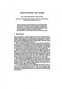
Fig. 1. ture.
A typical reactive real-time embedded system architec-
automatic synthesis from this high level of abstraction to ensure implementations that are “correct by construction.” Validation through simulation or verification should be done as much as possible at the higher levels of abstraction. A typical hardware architecture for an embedded system is illustrated in Fig. 1. This type of architecture combines custom hardware with embedded software, lending a certain measure of complexity and heterogeneity to the design. Even within the software or hardware portions themselves, however, there is often heterogeneity. In software, control-oriented processes might be mixed under the supervision of a multitasking real-time kernel running on a microcontroller. In addition, hard-real-time tasks may run cooperatively on one or more programmable DSP’s. The design styles used for these two software subsystems are likely to be quite different from one another, and testing the interaction between them is unlikely to be trivial. The hardware side of the design will frequently contain one or more ASIC’s, perhaps designed using logic or behavioral synthesis tools. On the other hand, a significant part of the hardware design most likely consists of interconnections of commodity components, such as processors and memories. Again, this time on the hardware side, we find heterogeneity. The design styles used to specify and simulate the ASIC’s and the interconnected commodity components are likely to be quite different. A typical system, therefore, not only mixes hardware design with software design, but also mixes design styles within each of these categories. Most often the set of tasks that the system implements are not specified in a rigorous and unambiguous fashion, so the design process requires several iterations to obtain convergence. Moreover, during the design process, the level of abstraction, detail, and specificity in different parts of the design varies. To complicate matters further, the skill sets and design styles used by different engineers on the project are likely to be different. The net result is that during the design process, many different specification and modeling techniques will be used. Managing the design complexity and heterogeneity is the key problem. We believe that the use of formal models and high-level synthesis for ensuring safe and correct designs depends on understanding the interaction between diverse
II. SPECIFICATION AND MODELING The design process is often viewed as a sequence of steps that transforms a set of specifications described informally into a detailed specification that can be used for manufacturing. All the intermediate steps are characterized by a transformation from a more abstract description to a more detailed one. A designer can perform one or more steps in this process. For the designer, the “input” description is a specification, the final description of the design is an implementation. For example, a software designer may see a set of routines written in C as an implementation of her/his design even though several other steps may be taken before the design is ready for manufacturing. During this process, verification of the quality of the design with respect to the demands placed on its performance and functionality has to be carried out. Unfortunately, the descriptions of the design at its various stages are often informal and not logically connected by a set of precise relationships. We advocate a design process that is based on representations with precise mathematical meaning so that both the verification and the map from the initial description to the various intermediate steps can be carried out with tools of guaranteed performance. Such an approach is standard in certain communities, where languages with strong formal properties are used to ensure robust design. Examples include ML [2], dataflow languages (e.g., Lucid [3] and Haskell [4]) and synchronous languages (e.g., Lustre, Signal, and Estrel [5]). There is a broad range of potential formalizations of a design, but most tools and designers describe the behavior of a design as a relation between a set of inputs and a set of outputs. This relation may be informal, even expressed in natural language. It is easy to find examples where informal specifications resulted in unnecessary redesigns. In our opinion, a formal model of a design should consist of the following components. 1) A functional specification, given as a set of explicit or implicit relations which involve inputs, outputs, and possibly internal (state) information.1 2) A set of properties that the design must satisfy, given as a set of relations over inputs, outputs, and states, that can be checked against the functional specification. 1 Later we will define inputs, outputs, and state information. For now, consider them as sequences of values.
EDWARDS et al.: DESIGN OF EMBEDDED SYSTEMS: FORMAL MODELS, VALIDATION, AND SYNTHESIS
367
3) A set of performance indexes that evaluate the quality of the design in terms of cost, reliability, speed, size, etc., given as a set of equations involving, among other things, inputs and outputs. 4) A set of constraints on performance indexes, specified as a set of inequalities. The functional specification fully characterizes the operation of a system, while the performance constraints bound the cost (in a broad sense). The set of properties is redundant, in that in a properly constructed design, the functional specification satisfies these properties. However, the properties are listed separately because they are simpler and more abstract (and also incomplete) compared to the functional specification. A property is an assertion about the behavior, rather than a description of the behavior. It is an abstraction of the behavior along a particular axis. For example, when designing a network protocol, we may require that the design never deadlock (this is also called a liveness property). Note that liveness does not completely specify the behavior of the protocol; it is instead a property we require our protocol to have. For the same protocol, we may require that any request will eventually be satisfied (this is also called fairness). Again this does not completely specify the behavior of the protocol but it is a required property. Given a formal model of the functional specifications and of the properties, we can classify properties in three groups: 1) properties that are inherent in the model of computation (i.e., they can be shown formally to hold for all specifications described using that model); 2) properties that can be verified syntactically for a given specification (i.e., they can be shown to hold with a simple—usually polynomial—time analysis of the specification); 3) properties that must be verified semantically for a given specification (i.e., they can be shown to hold by executing, at least implicitly, the specification for all inputs that can occur). For example, consider the property of determinate behavior, i.e., the fact that the output of a system depends only on its inputs and not on some internal, hidden choice. Any design described by a dataflow network (a formal model to be described later) is determinate, and hence this property need not be checked. If the design is represented by a network of finite-state machines (FSM’s), determinacy can be assessed by inspection of the state transition function. In some discrete event models (for example those embodied in Verilog and VHDL) determinacy is difficult to prove: it must be checked by exhaustive simulation. The design process takes a model of the design at a level of abstraction and refines it to a lower one. In doing so, the designer must ensure that the properties at that level of abstraction are verified, that the constraints are satisfied, and that the performance indexes are satisfactory. The refinement process involves also mapping constraints, 368
Fig. 2. An example of a design refinement stage, which uses hardware and software synthesis to translate a functional specification into a model of hardware.
performance indexes, and properties to the lower level so that they can be computed for the next level down.2 Fig. 2 shows a key refinement stage in embedded system design. The more abstract specification in this case is an executable functional model that is closer to the problem level. The specification undergoes a synthesis process (which may be partly manual) that generates a model of an implementation in hardware. That model itself may still be fairly abstract, capturing for example only timing properties. In this example the model is presumably used for hardware/software partitioning. While Fig. 2 suggests a purely top-down process, any real design needs more interaction between specification and implementation. Nonetheless, when a design is complete, the best way to present and document it is top down. This is enough to require that the methodology support top-down design. A. Elements of a Model of Computation A language is a set of symbols, rules for combining them (its syntax), and rules for interpreting combinations of symbols (its semantics). Two approaches to semantics have evolved: denotational and operational. A language can have both (ideally they are consistent with one another, although in practice this can be difficult to achieve). Operational semantics, which dates back to Turing machines, gives meaning of a language in terms of actions taken by some abstract machine and is typically closer to the implementation. Denotational semantics, first developed by Scott and Strachey [7], gives the meaning of the language in terms of relations. How the abstract machine in an operational semantics can behave is a feature of what we call the model of computation underlying the language. The kinds of relations that are possible in a denotational semantics is also a feature of the model of computation. Other features include communication style, how individual behavior is aggregated to make more complex compositions, and how hierarchy abstracts such compositions. 2 The refinement process can be defined formally once the models of the design are formally specified by McMillan [6].
PROCEEDINGS OF THE IEEE, VOL. 85, NO. 3, MARCH 1997
A design (at all levels of the abstraction hierarchy from functional specification to final implementation) is generally represented as a set of components, which can be considered as isolated monolithic blocks, interacting with each other and with an environment that is not part of the design. The model of computation defines the behavior and interaction of these blocks. In the sections that follow, we present a framework for comparing elements of different models of computation, called the tagged-signal model, and use it to contrast different styles of sequential behavior, concurrency, and communication. We will give precise definitions for a number of terms, but these definitions will inevitably conflict with standard usage in some communities. We have discovered that, short of abandoning the use of most common terms, no terminology can be consistent with standard usage in all related communities. Thus we attempt to avoid confusion by being precise, even at the risk of being pedantic. 1) The Tagged-Signal Model: Lee and Sangiovanni– Vincentelli have proposed the tagged-signal model [8], a formalism for describing aspects of models of computation for embedded system specification. It is denotational in the Scott and Strachey [7] sense, and it defines a semantic framework (of signals and processes) within which models of computation can be studied and compared. It is very abstract—describing a particular model of computation involves imposing further constraints that make it more concrete. The fundamental entity in the tagged-signal model is an event—a value/tag pair. Tags are often used to denote temporal behavior. A set of events (an abstract aggregation) is a signal. Processes are relations on signals, expressed as sets of -tuples of signals. A particular model of computation is distinguished by the order it imposes on tags and the character of processes in the model. Given a set of values and a set of tags , an event is , i.e., an event has a tag and a value. a member of A signal is a set of events. A signal can be viewed as a . A functional signal is a (possibly partial) subset of function from to . The set of all signals is denoted . A tuple of signals is denoted , and the set of all such tuples is denoted . The different models of time that have been used to model embedded systems can be translated into different order relations on the set of tags in the tagged-signal model. In particular, in a timed system is totally ordered, i.e., there is a binary relation on members of such that if , , and , then either or In an untimed system, is only partially ordered. A process with signals is a subset of the set of all -tuples of signals, for some . A particular is said to satisfy the process if . An that satisfies a process is called a behavior of the process. Thus a process is a set of possible behaviors, or a relation between signals. For many (but not all) applications, it is natural to partition the signals associated with a process into inputs and outputs. Intuitively, the process does not determine the
values of the inputs and does determine the values of the outputs. If , then is a partition of A process with inputs and outputs is a subset of In other words, a process defines a relation between input signals and output signals. A -tuple is said to satisfy if It can be written , where is an -tuple of input signals for process and is an -tuple of output signals for process . If the input signals are given by then the set describes the inputs, and is the set of behaviors consistent with the input . A process is functional with respect to a partition if to it is a single-valued, possibly partial, mapping from . That is, if and , then . In this case, we can write , where is a (possibly partial) function. Given the input signals, the output signals are determined (or there is unambiguously no behavior). Consider, as a motivating example introducing these several mechanisms to denote temporal behavior, the problem of modeling a time-invariant dynamical system on a computer. The underlying mathematical model, a set of differential equations over continuous time, is not directly implementable on a digital computer, due to the double quantization of real numbers into finite bit strings, and of time into clock cycles. Hence a first translation is required, by means of an integration rule, from the differential equations to a set of difference equations, that are used to compute the values of each signal with a given tag from the values of some other signals with previous and/or current tags. If it is possible to identify several strongly connected components in the dependency graph,3 then the system is decoupled. It becomes then possible to go from the total order of tags implicit in physical time to a partial order imposed by the depth-first ordering of the components. This partial ordering gives us some freedom in implementing the integration rule on a computer. We could, for example, play with scheduling by embedding the partial order into the total order among clock cycles. It is often convenient, for example, to evaluate a component completely, for all tags, before evaluating components that depend on it. Or it is possible to spread the computation among multiple processors. In the end, time comes back into the picture, but the double mapping, from total to partial order, and back to total order again, is essential to: 1) prove properties about the implementation (e.g., stability of the integration method, a bound on the maximum execution time, etc.); 2) optimize the implementation with respect to a given cost function (e.g., size of the buffers required to hold intermediate signals versus execution time, satisfaction of a constraint on the maximum execution time, etc.). 3 A directed graph with a node for each signal and an edge between two signals whenever the equation for the latter depends on the former.
EDWARDS et al.: DESIGN OF EMBEDDED SYSTEMS: FORMAL MODELS, VALIDATION, AND SYNTHESIS
369
2) State: Most models of computation include components with state, where behavior is given as a sequence of state transitions. In order to formalize this notion, let us consider a process that is functional with respect to partition . Let us assume for the moment that belongs to a timed system, in which tags are totally ordered. Then for any tuple of signals , we can define to be a tuple of the (possibly empty) subset of the events in with tags greater than . Two input signal tuples , are in relation (denoted if implies . This definition intuitively means that process cannot distinguish between the “histories” of and prior to time . Thus if the inputs are identical after time , then the outputs will also be identical. is an equivalence relation, partitioning the set of input signal tuples into equivalence classes for each . Following a long tradition, we call these equivalence classes the states of . In the hardware community, components with only one state for each are called combinational, while components with more than one state for some are called sequential. Note, however, that the term “sequential” is used in very different ways in other communities. 3) Decidability: Components with a finite number of states differ significantly from those with an infinite number of states. For certain infinite-state models (those that are Turing-complete), many desirable properties are undecidable—they cannot be determined in a finite amount of time for all systems. These properties include whether a system will need more memory than is available, whether a system will halt, and how fast a system will run [9]. Undecidability is not an insurmountable barrier and decidability is not sufficient to answer all questions in practice (e.g., because the required run-time may be prohibitive). Many successful systems have been designed using undecidable languages (i.e., those in which questions about some programs are undecidable). Although no algorithm can solve an undecidable problem for all systems, algorithms exist that can solve them for most systems. Buck’s Boolean Dataflow scheduler [10], for example, can answer the halting and bounded memory problems for many systems specified in a Turing-complete dataflow model, although it does, necessarily, fail to reach a conclusion for some systems. The nonterminating nature of embedded systems opens the possibility of using infinite time to solve certain undecidable problems. Parks’ scheduler [11], for example, will execute a potentially infinite-state system forever in bounded memory if it is possible to do so. However, it does not answer the question of how much memory is needed or whether the program will eventually halt. The classical von Neumann model of computation4 is a familiar model of sequential behavior. A memory stores the state and a processor advances the state through a sequence of memory operations. Most commonly-used programming languages (e.g., C, C , Lisp, Pascal, and FORTRAN)
use this model of computation. Often, the memory is viewed as having an unbounded number of finite-valued words, which, when coupled with an appropriate choice of processor instructions, makes the model Turing complete.5 Modern computer systems make this model practical by simulating unbounded memory with an elaborate hierarchy (registers, cache, RAM, and hard disk). Few embedded systems, however, can currently afford such a scheme. 4) Concurrency and Communication: While sequential or combinational behavior is related to individual processes, embedded systems will typically contain several coordinated concurrent processes. At the very least, such systems interact with an environment that evolves independently, at its own speed. But it is also common to partition the overall model into tasks that also evolve more or less independently, occasionally (or frequently) interacting with one another. Communication between processes can be explicit or implicit. In explicit communication, a sender process informs one or more receiver processes about some part of its state. In implicit communication, two or more processes share a common notion of state. Time plays a larger role in embedded systems than in classical computation. In classical transformational systems, the correct result is the primary concern—when it arrives is less important (although whether it arrives, the termination question, is important). By contrast, embedded systems are usually real-time systems, where the time at which a computation takes place can be more important than the computation itself. As we discussed above, different models of time become different order relations on the set of tags in the taggedsignal model. Recall that in a timed system is totally ordered, while in an untimed system is only partially ordered. Implicit communication generally requires totally ordered tags, usually identified with physical time. The tags in a metric-time system have the notion of a “distance” between them, much like physical time. Formally, there exists a partial function mapping pairs of tags to real numbers such that and A discrete-event (DE) system is a timed system where the tags in each signal are order-isomorphic with the integers (for a two-sided system) or the natural numbers (for a onesided system) [8]. Intuitively, this means that any pair of ordered tags has a finite number of intervening tags. Two events are synchronous if they have the same tag. Two signals are synchronous if each event in one signal is synchronous with an event in the other signal and vice versa. A system is synchronous if every signal in the system is synchronous with every other signal in the system. A discrete-time system is a synchronous DE system. Synchronous/reactive languages [5] are synchronous in exactly this sense. The set of tags in a behavior of the system denotes a global “clock” for the system. Every signal conceptually has an event at every tag, although in
4 It is formalized in the abstract model called random access machine or random access stored program [12].
5 Turing-completeness can be obtained also with a finite number of infinite-valued words.
370
PROCEEDINGS OF THE IEEE, VOL. 85, NO. 3, MARCH 1997
some models this event could have a value denoting the absence of an event (called bottom). At each clock tick, each process maps input values to output values. If cyclic communication is allowed, then some mechanism must be provided to resolve or prevent circular dependencies. One possibility is to constrain the output values to have tags corresponding to the next tick. Another possibility (all too common) is to leave the result unspecified, resulting in nondeterminacy (or worse, infinite computation within one tick). A third possibility is to use fixed-point semantics, where the behavior of the system is defined as a set of events that satisfy all processes. Concurrency in physical implementations of systems occurs through some combination of parallelism, having physically distinct computational resources, and interleaving, sharing of a common physical resource. Mechanisms for achieving interleaving vary widely, ranging from operating systems that manage context switches to fully static interleaving in which concurrent processes are converted (compiled) into a single nonconcurrent process. We focus here on the mechanisms used to manage communication between concurrent processes. Parallel physical systems naturally share a common notion of time, according to the laws of physics. The time at which an event in one subsystem occurs has a natural ordering relationship with the time at which an event occurs in another subsystem. Physically interleaved systems also share a natural common notion of time. Logical systems, on the other hand, need a mechanism to explicitly share a notion of time. Consider two imperative programs interleaved on a single processor under the control of time-sharing operating system. Interleaving creates a natural ordering between events in the two processes, but this ordering is generally unreliable because it heavily depends on scheduling policy system load, and so on. Some synchronization mechanism is required if those two programs need to cooperate. More generally, in logically concurrent systems, maintaining a coherent global notion of time as a total order on events, can be extremely expensive. Hence in practice this is replaced whenever possible with an explicit synchronization, in which this total order is replaced by a partial order. Returning to the example of two processes running under a time-sharing operating system, we take precautions to ensure an ordering of two events only if the ordering of these two events matters. A variety of mechanisms for managing the order of events, and hence for communicating information between processes, has arisen. Some of the most common ones are listed below. • Unsynchronized: In an unsynchronized communication, a producer of information and a consumer of the information are not coordinated. There is no guarantee that the consumer reads valid information produced by the producer, and there is no guarantee that the producer will not overwrite previously produced data before the consumer reads the data. In the taggedsignal model, the repository for the data is modeled
•
•
•
•
as a process, and the reading and writing events have no enforced ordering relationship between their tags. Read-modify-write: Commonly used for accessing shared data structures, this strategy locks a data structure between a read and write from a process, preventing any other accesses. In other words, the actions of reading, modifying, and writing are atomic (indivisible). In the tagged-signal model, the repository for the data is modeled as a process where events associated with this process are totally ordered (resulting in a globally partially ordered model). The read-modify-write is modeled as a single event. Unbounded First-In First-Out (FIFO) buffered: This is a point-to-point communication strategy, where a producer generates a sequence of data tokens and consumer consumes these tokens, but only after they have been generated. In the tagged-signal model, this is a simple connection where the signal on the connection is constrained to have totally ordered tags. The tags model the ordering imposed by the FIFO model. If the consumer implements blocking reads, then it imposes a total order on events at all its input signals. This model captures essential properties of both Kahn process networks and dataflow [13]. Bounded FIFO buffered: In this case, the data repository is modeled as a process that imposes ordering constraints on its inputs (which come from the producer) and the outputs (which go to the consumer). Each of the input and output signals are internally totally ordered. The simplest case is where the size of the buffer is one, in which case the input and output events must be interleaved so that each output event lies between two input events. Larger buffers impose a maximum difference (often called synchronic distance) between the number of input and output events. Note that some implementations of this communication mechanism may not really block the writing process when the buffer is full, thus requiring some higher level of flow control to ensure that this never happens, or that it does not cause any harm. Rendezvous: In the simplest form of rendezvous, implemented, i.e., in Occam and Lotos, a single writing process and a single reading process must simultaneously be at the point in their control flow where the write and the read occur. It is a convenient communication mechanism, because it has the semantics of a single assignment, in which the writer provides the right-hand side, and the reader provides the left-hand side. In the tagged-signal model, this is imposed by events with identical tags [8]. Lotos offers, in addition, multiple rendezvous, in which one among multiple possible communications is nondeterministically selected. Multiple rendezvous is more flexible than single rendezvous, because it allows the designer to specify more easily several “expected” communication ports at any given time, but it is very difficult and expensive to implement correctly.
EDWARDS et al.: DESIGN OF EMBEDDED SYSTEMS: FORMAL MODELS, VALIDATION, AND SYNTHESIS
371
Table 1
A Comparison of Concurrency and Communication Schemes
Unsynchronized Read-Modify-Write Unbounded FIFO Bounded FIFO Single Rendezvous Multiple Rendezvous
Transmitters many many one one one one
Receivers many many one one one one
Buffer Size one one unbounded bounded one one
Of course, various combinations of the above models are possible. For example, in a partially unsynchronized model, a consumer of data may be required to wait until the first time a producer produces data, after which the communication is unsynchronized. The essential features of the concurrency and communication styles described above are presented in Table 1. These are distinguished by the number of transmitters and receivers (e.g., broadcast versus point-to-point communication), the size of the communication buffer, whether the transmitting or receiving process may continue after an unsuccessful communication attempt (blocking reads and writes), and whether the result of each write can be read at most once (single reads).
Blocking Reads no yes yes yes yes no
Blocking Writes no yes no maybe yes no
Single Reads no no yes yes yes yes
(a)
(b)
(c)
(d)
Fig. 3. Simultaneous events in a DE system. (a) Process A produces events with the same time stamp. Should B or C be fired next? (b) Zero-delay process B has fired. How many times should C be fired? (c) Delta-delay process B has fired; C will consume A’s output next. (d) C has fired once; it will fire again to consume B’s output.
B. Common Models of Computation We are now ready to use the scheme developed in the previous section to classify and analyze several models of computation that have been used to describe embedded systems. We will consider issues such as ease of modeling, efficiency of analysis (simulation or formal verification), automated synthesizability, optimization space versus overspecification, and so on. 1) Discrete Event: Time is an integral part of a DE model of computation. Events usually carry a totally ordered time stamp indicating the time at which the event occurs. A DE simulator usually maintains a global event queue that sorts events by time stamp. Digital hardware is often simulated using a DE approach. The Verilog language, for example, was designed as an input language for a DE simulator. The VHDL language also has an underlying DE model of computation. DE modeling can be expensive—sorting time stamps can be time-consuming. Moreover, ironically, although DE is ideally suited to modeling distributed systems, it is very challenging to build a distributed DE simulator. The global ordering of events requires tight coordination between parts of the simulation, rendering distributed execution difficult. Discrete-event simulation is most efficient for large systems with large, frequently idle or autonomously operating sections. Under DE simulation, only the changes in the system need to be processed, rather than the whole system. As the activity of a system increases, the DE paradigm becomes less efficient because of the overhead inherent in processing time stamps. Simultaneous events, especially those arising from zerodelay feedback loops, present a challenge for DE models of computation. In such a situation, events may need to be ordered, but are not. 372
Consider the DE system shown in Fig. 3. Process B has zero delay, meaning that its output has the same time stamp as its input. If process A produces events with the same time stamp on each output, there is ambiguity about whether B or C should be invoked first, as shown in Fig. 3(a). Suppose B is invoked first, as shown in Fig. 3(b). Now, depending on the simulator, C might be invoked once, observing both input events in one invocation, or it might be invoked twice, processing the events one at a time. In the latter case, there is no clear way to determine which event should be processed first. The addition of delta delay makes such nondeterminacy easier to prevent, but does not avoid it completely. It introduces a two-level model of time in which each instant of time is broken into (a potentially infinite number of) totally ordered delta steps. The simulated time reported to the user, however, does not include delta information. A “zero-delay” process in this model actually has delta delay. For example, Process B would have delta delay, so firing A followed by B would result in the situation in Fig. 3(c). The next firing of C will see the event from A only; the firing after that will see the (delay-delayed) event from B. Other simulators, including the DE simulator in Ptolemy [14], attempt to statically analyze data precedences within a single time instant. Such precedence analysis is similar to that done in synchronous languages (Esterel, Lustre, and Signal) to ensure that simultaneous events are processed deterministically. It determines a partial ordering of events with the same time stamp by examining data precedences. Adding a feedback loop from Process C to A in Fig. 3 would create a problem if events circulate through the loop without any increment in time stamp. The same problem PROCEEDINGS OF THE IEEE, VOL. 85, NO. 3, MARCH 1997
occurs in synchronous languages, where such loops are called causality loops. No precedence analysis can resolve the ambiguity. In synchronous languages, the compiler may simply fail to compile such a program. Some DE simulators will execute the program nondeterministically, while others support tighter control over the sequencing through graph annotations. 2) Communicating Finite State Machines: FSM’s are an attractive model for embedded systems. The amount of memory required by such a model is always decidable, and is often an explicit part of its specification. Halting and performance questions are always decidable since each state can, in theory, be examined in finite time. In practice, however, this may be prohibitively expensive. A traditional FSM consists of: • a set of input symbols (the Cartesian product of the sets of values of the input signals); • a set of output signals (the Cartesian product of the sets of values of the output signals); • a finite set of states with a distinguished initial state; • an output function mapping inputs and states to outputs; • a next-state function mapping inputs and states to (next) states. The input to such a machine is a sequence of input symbols, and the output is a sequence of output symbols. Traditional FSM’s are good for modeling sequential behavior, but are impractical for modeling concurrency or memory because of the so-called state explosion problem. A single machine mimicking the concurrent execution of a group of machines has a number of states equal to the product of the number of states of each machine. A memory has as many states as the number of values that can be stored at each location raised to the power of the number of locations. The number of states alone is not always a good indication of complexity, but it often has a strong correlation. Harel advocated the use of three major mechanisms that reduce the size (and hence the visual complexity) of finite automata (FA) for modeling practical systems [15]. The first one is hierarchy, in which a state can represent an enclosed state machine. That is, being in a particular state has the interpretation that the state machine enclosed by is active. Equivalently, being in state means that the machine is in one of the states enclosed by . Under the latter interpretation, the states of are called “or states.” Or states can exponentially reduce the complexity (the number of states) required to represent a system. They compactly describe the notion of preemption (a high-priority event suspending or “killing” a lower priority task), that is fundamental in embedded control applications. The second mechanism is concurrency. Two or more state machines are viewed as being simultaneously active. Since the system is in one state of each parallel state machine simultaneously, these are sometimes called “and states.” They also provide a potential exponential reduction in the size of the system representation.
The third mechanism is nondeterminism. While often nondeterminism is simply the result of an imprecise (maybe erroneous) specification, it can be an extremely powerful mechanism to reduce the complexity of a system model by abstraction. This abstraction can either be due to the fact that the exact functionality must still be defined, or that it is irrelevant to the properties currently considered of interest. For example, during verification of a given system component, other components can be modeled as nondeterministic entities to compactly constrain the overall behavior. A system component can also be described nondeterministically to permit some optimization during the implementation phase. Non-determinism can also provide an exponential reduction in complexity. These three mechanisms have been shown in [16] to cooperate synergistically and orthogonally, to provide a potential triple exponential reduction in the size of the representation with respect to a single, flat deterministic FSM.6 Harel’s Statecharts model uses a synchronous concurrency model (also called synchronous composition). The set of tags is a totally ordered countable set that denotes a global “clock” for the system. The events on signals are either produced by state transitions or inputs. Events at a tick of the clock can trigger state transitions in other parallel state machines at the same clock. Unfortunately, Harel left open some questions about the semantics of causality loops and chains of instantaneous (same tick) events, triggering a flurry of activity in the community that has resulted in at least 20 variants of Statecharts [17]. Most of these 20 variants use the synchronous concurrency model. However, for many applications, the tight coordination implied by the synchronous model is inappropriate. In response to this, a number of more loosely coupled asynchronous FSM models have evolved, including behavioral FSM’s [18], SDL process networks [18], and codesign FSM’s [19]. A model that is closely related to FSM’s is the FA, which emphasize the acceptance or rejection of a sequence of inputs rather than the sequence of output symbols produced in response to a sequence of input symbols. Most notions, such as composition and so on, can be naturally extended from one model to the other. In fact, any of the concurrency models described in this paper can be usefully combined with FSM’s. In the Ptolemy project [14], FSM’s are hierarchically nested with dataflow, DE, or synchronous/reactive models [20]. The nesting is arbitrarily deep and can mix concurrency models at different levels of the hierarchy. This very flexible model is called “*charts” (“star charts”), where the asterisk is meant to suggest a wildcard. Control flow expressions (CFE’s) [21] have been recently proposed to represent the control flow of a set of operations 6 The exact claim in [16] was that “and” type nondeterminism (in which all nondeterministic choices must be successful), rather than hierarchical states, was the third source of exponential reduction together with “or” type nondeterminism and concurrency. Hierarchical states, on the other hand, were shown in that paper to be able to simulate “and” nondeterminism with only a polynomial increase in size.
EDWARDS et al.: DESIGN OF EMBEDDED SYSTEMS: FORMAL MODELS, VALIDATION, AND SYNTHESIS
373
in a cycle-based specification language. CFE’s are an algebraic model extending regular expressions [9] and can be compiled into FSM’s that can be used in the synthesis of a control unit. 3) Synchronous/Reactive: In a synchronous model of computation, all events are synchronous, i.e., all signals have events with identical tags. The tags are totally ordered and globally available. Simultaneous events (those in the same clock tick) may be totally ordered, partially ordered, or unordered, depending on the model of computation. Unlike the DE model, all signals have events at all clock ticks, simplifying the simulator by requiring no sorting. Simulators that exploit this simplification are called cycle-based or cycle-driven simulators. Processing all events at a given clock tick constitutes a cycle. Within a cycle, the order in which events are processed may be determined by data precedences, which define microsteps. These precedences are not allowed to be cyclic, and typically impose a partial order (leaving some arbitrary ordering decisions to the scheduler). Cycle-based models are excellent for clocked synchronous circuits and have also been applied successfully at the system level in certain signal processing applications. A cycle-based model is inefficient for modeling systems where events do not occur at the same rate in all signals. While conceptually such systems can be modeled (using, for example, special tokens to indicate the absence of an event), the cost of processing such tokens is considerable. Fortunately, the cycle-based model is easily generalized to multirate systems. In this case, every th event in one signal aligns with the events in another. A multirate cycle-based model is still somewhat limited. It is an excellent model for synchronous signal processing systems where sample rates are related by constant rational multiples, but in situations where the alignment of events in different signals is irregular, it can be inefficient. The more general synchronous/reactive model is embodied in the so-called synchronous languages [22]. Esterel [23] is a textual imperative language with sequential and concurrent statements that describe hierarchically arranged processes. Lustre [24] is a textual declarative language with a dataflow flavor and a mechanism for multirate clocking. Signal [25] is a textual relational language, also with a dataflow flavor and a more powerful clocking system. Argos [26], a derivative of Harel’s Statecharts [27], is a graphical language for describing hierarchical FSM’s. Halbwachs [5] gives a good summary of this group of languages. The synchronous/reactive languages describe systems as a set of concurrently-executing synchronized modules. These modules communicate through signals that are either present or absent in each clock tick. The presence of a signal is called an event, and often carries a value, such as an integer. The modules are reactive in the sense that they only perform computation and produce output events in instants with at least one input event. Every signal in these languages is conceptually (or explicitly) accompanied by a clock signal, which has meaning 374
relative to other clock signals and defines the global ordering of events. Thus when comparing two signals, the associated clock signals indicate which events are simultaneous and which precede or follow others. In the case of Signal and Lustre, clocks have complex interrelationships, and a clock calculus allows a compiler to reason about these ordering relationships and to detect inconsistencies in the definition. Esterel and Argos have simpler clocking schemes and focus instead on finite-state control. Most of these languages are static in the sense that they cannot request additional storage nor create additional processes while running. This makes them well-suited for bounded and speed-critical embedded applications, since their behavior can be extensively analyzed at compile time. This static property makes a synchronous program finitestate, greatly facilitating formal verification. Verifying that a synchronous program is causal (noncontradictory and deterministic) is a fundamental challenge with these languages. Since computation in these languages is delay-free and arbitrary interconnection of processes is possible, it is possible to specify a program that has either no interpretation (a contradiction where there is no consistent value for some signal) or multiple interpretations (some signal has more than one consistent value). Both situations are undesirable, and usually indicate a design error. A conservative approach that checks for causality problems structurally flags an unacceptably large number of programs as incorrect because most will manifest themselves only in unreachable program states. The alternative, to check for a causality problem in any reachable state, can be expensive since it requires an exhaustive check of the state space of the program. In addition to the ability to translate these languages into finite-state descriptions, it is possible to compile these languages directly into hardware. Techniques for translating both Esterel [28] and Lustre [29] into hardware have been proposed. The result is a logic network consisting of gates and flip-flops that can be optimized using traditional logic synthesis tools. To execute such a system in software, the resulting network is simply simulated. The technique is also the basis to perform more efficiently causality checks, by means of implicit state space traversal techniques [30]. 4) Dataflow Process Networks: In dataflow, a program is specified by a directed graph where the nodes (called actors) represent computations and the arcs represent totally ordered sequences (called streams) of events (called tokens). In Fig. 4(a), the large circles represent actors, the small circle represents a token, and the lines represent streams. The graphs are often represented visually and are typically hierarchical, in that an actor in a graph may represent another directed graph. The nodes in the graph can be either language primitives or subprograms specified in another language, such as C or FORTRAN. In the latter case, we are mixing two of the models of computation from Fig. 2, where dataflow serves as the coordination language for subprograms written in an imperative host language. Dataflow is a special case of Kahn process networks [13], [31]. In a Kahn process network, communication PROCEEDINGS OF THE IEEE, VOL. 85, NO. 3, MARCH 1997
(a)
(b) Fig. 4. (a) A dataflow process network and (b) a single-processor static schedule for it.
is by unbounded FIFO buffering, and processes are constrained to be continuous mappings from input streams to output streams. “Continuous” in this usage is a topological property that ensures that the program is determinate [13]. Intuitively, it implies a form of causality without time; specifically, a process can use partial information about its input streams to produce partial information about its output streams. Adding more tokens to the input stream will never result in having to change or remove tokens on the output stream that have already been produced. One way to ensure continuity is with blocking reads, where any access to an input stream results in suspension of the process if there are no tokens. One consequence of blocking reads is that a process cannot test an input channel for the availability of data and then branch conditionally to a point where it will read a different input. In dataflow, each process is decomposed into a sequence of firings, indivisible quanta of computation. Each firing consumes and produces tokens. Dividing processes into firings avoids the multitasking overhead of context switching in direct implementations of Kahn process networks. In fact, in many of the signal processing environments, a major objective is to statically (at compile time) schedule the actor firings, achieving an interleaved implementation of the concurrent model of computation. The firings are organized into a list (for one processor) or set of lists (for multiple processors). Fig. 4(a) shows a dataflow graph (DFG), and Fig. 4(b) shows a single processor schedule for it. This schedule is a list of firings that can be repeated indefinitely. One cycle through the schedule should return the graph to its original state (here, state is defined as the number of tokens on each arc). This is not always possible, but when it is, considerable simplification results [32]. In many existing environments, what happens within a firing can only be specified in a host language with imperative semantics, such as C or C . In the Ptolemy system [14], it can also consist of a quantum of computation specified with any of several models of computation, such as FSM’s, a synchronous/reactive subsystem, or a DE subsystem [33]. A useful formal device is to constrain the operation of a firing to be functional, i.e., a simple, stateless mapping from input values to output values. Note, however, that this
does not constrain the process to be stateless, since it can maintain state in a self-loop: an output that is connected back to one of its inputs. An initial token on this self-loop provides the initial value for the state. Many possibilities have been explored for precise semantics of dataflow coordination languages, including Karp and Miller’s computation graphs [34], Lee and Messerschmitt’s synchronous DFG’s [35], Lauwereins et al.’s cyclostatic dataflow model [36], [37], Kaplan et al.’s processing graph method (PGM) [38], granular lucid [39], and others [40]–[43]. Many of these limit expressiveness in exchange for formal properties (e.g., provable liveness and bounded memory). Synchronous dataflow (SDF) and cyclo-static dataflow require processes to consume and produce a fixed number of tokens for each firing. Both have the useful property that a finite static schedule can always be found that will return the graph to its original state. This allows for extremely efficient implementations [32]. For more general dataflow models, it is undecidable whether such a schedule exists [10]. A looser model of dataflow is the tagged-token model, in which the partial order of tokens is explicitly carried with the tokens [44]. A significant advantage of this model is that while it logically preserves the FIFO semantics of the channels, it permits out-of-order execution. Some examples of graphical dataflow programming environments intended for signal processing (including image processing) are Khoros [45] and Ptolemy [14]. 5) Other Models: Another commonly used partially ordered concurrency model is based on rendezvous. Two or more concurrent sequential processes proceed autonomously, but at certain points in their control flow, coordinate so that they are simultaneously at specified points. Rendezvous has been developed into elaborate process calculi (e.g., Hoare’s CSP [46] and Milner’s CCS [47]). It has also been implemented in the Occam and Lotos programming languages. Ada also uses rendezvous, although the implementation is stylistically quite different, using remote procedure calls rather than more elementary synchronization primitives. Rendezvous-based models of computation are often called synchronous. However, by the definition we have given, they are not synchronous. Events are partially ordered, not totally ordered, with rendezvous points imposing the partial ordering constraints. No discussing of concurrent models of computation would be complete without mentioning Petri nets [48], [49]. Petri nets are, in their basic form, neither Turing complete nor finite state. They are interesting as uninterpreted model for several very different classes of problems, including some relevant to embedded system design (e.g., process control, asynchronous communication, scheduling, etc.). Many questions about Petri nets can be answered in finite time. Moreover, a large user community has developed a large body of theoretical results and practical design aids and methods based on them. In particular, partial orderbased verification methods [50], [51], [6] are one possible
EDWARDS et al.: DESIGN OF EMBEDDED SYSTEMS: FORMAL MODELS, VALIDATION, AND SYNTHESIS
375
answer to the state explosion problem plaguing FSM-based verification techniques. C. Languages The distinction between a language and its underlying model of computation is important. The same model of computation can give rise to fairly different languages (e.g., the imperative Algol-like languages C, C , Pascal, and FORTRAN). Some languages, such as VHDL and Verilog, support two or more models of computation.7 The model of computation affects the expressiveness of a language—which behaviors can be described in the language, whereas the syntax affects compactness, modularity, and reusability. Thus, for example, object-oriented properties of imperative languages like C are more a matter of syntax than a model of computation. The expressiveness of a language is an important issue. At one extreme, a language that is not expressive enough to specify a particular behavior is clearly unsuitable, but the other extreme also raises problems. A language that is too expressive often raises the complexity of analysis and synthesis. In fact, for very expressive languages, many analysis and synthesis problems become undecidable: no algorithm will solve all problem instances in finite time. A language in which a desired behavior cannot be represented succinctly is also problematic. The difficulty of solving analysis and synthesis problems is at least linear in the size of the problem description, and can be as bad as several times exponential, so choosing a language in which the desired behavior of the system is compact can be critical. A language may be very incomplete and/or very abstract. For example, it may specify only the interaction between computational modules, and not the computation performed by the modules. Instead, it provides an interface to a host language that specifies the computation, and is called a coordination language (i.e., Linda [41], Granular Lucid [39], and Ptolemy domains [14]). Or the language may specify only the causality constraints of the interactions without detailing the interactions themselves nor providing an interface to a host language. In this case, the language is used as a tool to prove properties of systems, as done, for example, in process calculi [46], [47] and Petri nets [48], [49]. In still more abstract modeling, components in the system are replaced with nondeterminate specifications that give constraints on the behavior, but not the behavior itself. Such abstraction provides useful simplifications that help formal verification. D. Heterogeneous Models of Computation The variety of models of computation that have been developed is only partially due to immaturity in the field. It appears that different models fundamentally have different strengths and weaknesses, and that attempts to find their 7 They
directly support the Imperative model within a process, and the Discrete Event model among processes. They can also support Extended FSM’s under suitable restrictions known as the “synthesizable subset.” 376
common features result in models that are very low level, difficult to use. These low level models (such as Dijkstra’s P/V systems [52]) provide a good theoretical foundation, but not a good basis for design. Thus we are faced with two alternatives in designing complex, heterogeneous systems. We can either use a single unified approach and suffer the consequences, or we can mix approaches. To use the unified approach today we could choose between VHDL and C for a mixed hardware and software design, doing the entire design in one or the other (i.e., specifying the software in VHDL or the hardware in C). Or worse, we could further bloat the VHDL language by including a subset designed for software specification (e.g., by making Ada a subset of VHDL). In the alternative that we advocate, we mix approaches while keeping them conceptually distinct, for example by using both VHDL and C in a mixed hardware/software design. The key problem in the mixed approach, then, is to define the semantics of the interaction of fundamentally different models of computation. It is not simply a problem of interfacing languages. It is easy, for example, to provide a mechanism for calling C procedures from VHDL. But what does it mean if two concurrent VHDL entities call C procedures that interact? The problem is exacerbated by the lack of agreed-upon semantics for C or VHDL. Studying the interaction semantics of mixed models of computation is the main objective of the Ptolemy project [14]. There, a hierarchical framework is used, where a specification in one model of computation can contain a primitive that is internally implemented using another model of computation. The object-oriented principle of information hiding is used to isolate the models from one another as much as possible. III. VALIDATION Validation loosely refers to the process of determining that a design is correct. Simulation remains the main tool to validate a model, but the importance of formal verification is growing, especially for safety-critical embedded systems. Although still in its infancy, it shows more promise than verification of arbitrary systems, such as generic software programs, because embedded systems are often specified in a more restricted way. For example, they are often finite-state. Many safety properties (including deadlock detection) can be detected in a time-independent way using existing model checking and language containment methods [53], [54]. Unfortunately, verifying most temporal properties is much more difficult [55]. Much more research is needed before this is practical.
A. Simulation Simulating embedded systems is challenging because they are heterogeneous. In particular, most contain both software and hardware components that must be simulated at the same time. This is the co-simulation problem. PROCEEDINGS OF THE IEEE, VOL. 85, NO. 3, MARCH 1997
Table 2
A Comparison of Co-Simulation Methods
Author Gupta [56] Rowson [57] Wilson [58] Thomas [59] ten Hagen (1) [60] ten Hagen (2) [60] Kalavade (1) [61] Kalavade (2) [61] Lee [61] Suterwala [62]
Hardware Simulation logic custom logic commercial logic commercial logic commercial logic commercial cycle-based logic custom logic custom logic custom logic commercial
The basic co-simulation problem is reconciling two apparently conflicting requirements: • to execute the software as fast as possible, often on a host machine that may be faster than the final embedded CPU and certainly is very different from it; and • to keep the hardware and software simulations synchronized, so that they interact just as they will in the target system. One approach, often taken in practice, is to use a generalpurpose software simulator (e.g., based on VHDL or Verilog) to simulate a model of the target CPU, executing the software program on this simulation model. Different models can be employed, with a tradeoff between accuracy and performance. • Gate-level models. These are viable only for small validation problems, where either the processor is a simple one, or very little code needs to be run on it, or both. • Instruction-set architecture (ISA) models augmented with hardware interfaces. An ISA model is a standard processor simulator (often written in C) augmented with hardware interface information for coupling to a standard logic simulator. • Bus-functional models. These are hardware models only of the processor interface; they cannot run any software. Instead, they are configured (programmed) to make the interface appear as if software were running on the processor. A stochastic model of the processor and of the program can be used to determine the mix of bus transactions. • Translation-based models. These convert the code to be executed on a processor into code that can be executed natively on the computer doing the simulation. Preserving timing information and coupling the translated code to a hardware simulator are the major challenges. When more accuracy is required and acceptable simulation performance is not achievable on standard computers, designers sometimes resort to emulation. In this case, configurable hardware emulates the behavior of the system being designed. Another problem is the accurate modeling of a controlled electromechanical system, which is generally governed by a
Software Simulation bus-cycle custom host-compiled host-compiled host-compiled host-compiled cycle-counting host-compiled ISA host-compiled ISA on HW simulation
Synchronization Mechanism single simulation handshake handshake handshake handshake tagged messages single simulation single simulation single simulation single simulation
set of differential equations. This often requires interfacing to an entirely different kind of simulator. 1) Co-Simulation Methods: In this section, we present a survey of some of the representative co-simulation methods, summarized in Table 2. A unified approach, where the entire system is translated into a form suitable for a single simulator, is conceptually simple, but computationally inefficient. Making better use of computational resources often means distributing the simulation, but synchronization of the processes becomes a challenge. The method proposed by Gupta et al. [56] is typical of the unified approach to co-simulation. It relies on a single custom simulator for hardware and software that uses a single event queue and a high-level, bus-cycle model of the target CPU. Rowson [57] takes a more distributed approach that loosely links a hardware simulator with a software process, synchronizing them with the standard interprocess communication mechanisms offered by the host operating system. One of the problems with this approach is that the relative clocks of software and hardware simulation are not synchronized. This requires the use of handshaking protocols, which may impose an undue burden on the implementation. This may happen, for example, because hardware and software would not need such handshaking since the hardware part runs in reality much faster than in the simulation. Wilson [58] describes the use of a commercial hardware simulator. In this approach, the simulator and software compiled on the host processor interact via a bus-cycle emulator inside the hardware simulator. The software and hardware simulator execute in separate processes and the two communicate via UNIX pipes. Thomas et al. [59] take a similar approach. Another approach keeps track of time in software and hardware independently, using various mechanisms to synchronize them periodically. For example, ten Hagen et al. [60] describe a two-level co-simulation environment that combines a timed and untimed level. The untimed level is used to verify time-independent properties of the system, such as functional correctness. At this level, software and hardware run independent of each other, passing messages whenever needed. This allows the simulation to run at the maximum speed, while taking full advantage of the native debugging environments both for software and for
EDWARDS et al.: DESIGN OF EMBEDDED SYSTEMS: FORMAL MODELS, VALIDATION, AND SYNTHESIS
377
hardware. The timed level is used to verify time-dependent properties, requiring the definition of time in hardware and software. In hardware, time can be measured either on the basis of clock cycles (cycle-based simulation, assuming synchronous operation) for maximum performance, or on the basis of estimated or extracted timing information for maximum precision. In software, on the other hand, time can be measured either by profiling or clock cycle counting information for maximum performance, or by executing a model of the CPU for maximum precision. The authors propose two basic mechanisms for synchronizing time in hardware and software. 1) Software is the master and hardware is the slave. In this case, software decides when to send a message, tagged with the current software clock cycle, to the hardware simulator. Depending on the relation between software and hardware time, the hardware simulator can either continue simulation until software time or back-up the simulation to software time (this requires checkpointing capabilities, which few hardware simulators currently have). 2) Hardware is the master and software is the slave. In this case, the hardware simulator directly calls communication procedures which, in turn, call user software code. Kalavade and Lee [61] and Lee and Rabaey [63] take a similar approach. The simulation and design environment Ptolemy [14] is used to provide an interfacing mechanism between different domains. In Ptolemy, objects described at different levels of abstraction and using different semantic models are composed hierarchically. Each abstraction level, with its own semantic model, is a “domain” (e.g., dataflow, DE). Atomic objects (called “stars”) are the primitives of the domain (e.g., dataflow operators, logic gates). They can be used either in simulation mode (reacting to events by producing events) or in synthesis mode (producing software or a hardware description). “Galaxies” are collections of instances of stars or other galaxies. An instantiated galaxy can belong to a domain different than the instantiating domain. Each domain includes a scheduler, which decides the order in which stars are executed, both in simulation and in synthesis. For synthesis, it must be possible to construct the schedule statically. Whenever a galaxy instantiates a galaxy belonging to another domain (typical in co-simulation), Ptolemy provides a mechanism called a “wormhole” for the two schedulers to communicate. The simplest form of communication is to pass time-stamped events across the interface between domains, with the appropriate data-type conversion. Kalavade and Lee [61] perform co-simulation at the specification level by using a dataflow model and at the implementation level by using an ISA processor model augmented with the interfaces within a hardware simulator, both built within Ptolemy. Lee and Rabaey [63] simulate the specification by using concurrent processes communicating via queues within 378
a timed model (the Ptolemy communicating processes domain). The same message exchanging mechanism is retained in the implementation (using a mix of microprocessor-based boards, DSP’s, and ASIC’s), thus performing co-simulation of one part of the implementation with a simulation model of the rest. For example, the software running on the microprocessor can also be run on a host computer, while the DSP software runs on the DSP itself. Sutarwala and Paulin [62] describe an environment coupled with a retargetable compiler [64] for cycle-based simulation of a user-definable DSP architecture. The user only provides a description of the DSP structure and functionality, while the environment generates a behavioral bus-cycle VHDL model for it, which can then be used to run the code on a standard hardware simulator. B. Formal Verification Formal verification is the process of mathematically checking that the behavior of a system, described using a formal model, satisfies a given property, also described using a formal model. The two models may or may not be the same, but must share a common semantic interpretation. The ability to carry out formal verification is strongly affected by the model of computation, which determines decidability and complexity bounds. Two distinct types of verification arise. • Specification Verification: checking an abstract property of a high-level model. An example: checking whether a protocol modeled as a network of communicating FSM’s can ever deadlock. • Implementation Verification: checking if a relatively low-level model correctly implements a higher-level model or satisfies some implementation-dependent property. For example: checking whether a piece of hardware correctly implements a given FSM, or whether a given dataflow network implementation on a given DSP completely processes an input sample before the next one arrives. Implementation verification for hardware is a relatively well-developed area, with the first industrial-strength products beginning to appear. For example, most logic synthesis systems have a mechanism to verify a gate-level implementation against a set of Boolean equations or an FSM, to detect bugs in the synthesis software.8 While simulation could fall under these definitions (if the property is “the behavior under this stimulus is as expected”), the term formal verification is usually reserved for checking properties of the system that must hold for all or a broad class of inputs. The properties are traditionally broken into two classes: • safety properties, which state that no matter what inputs are given, and no matter how nondeterministic choices are resolved inside the system model, the system will not get into a specific undesirable 8 This shows that the need for implementation verification is not eliminated by the introduction of automated synthesis techniques.
PROCEEDINGS OF THE IEEE, VOL. 85, NO. 3, MARCH 1997
configuration (e.g., deadlock, emission of undesired outputs, etc.); • liveness properties, which state that some desired configuration will be visited eventually or infinitely often (e.g., expected response to an input, etc.) More complex checks, such as the correct implementation of a specification, can usually be done in terms of those basic properties. For example, Dill [65] describes a method to define and check correct implementation for asynchronous logic circuits in an automata-theoretic framework. In this section we only summarize the major approaches that have been or can be applied to embedded system verification. These can be roughly divided into the following classes. • Theorem proving methods provide an environment that assists the designer in carrying out a formal proof of specification or implementation correctness. The assistance can be either in the form of checking the correctness of the proof, or in performing some steps of the proof automatically (e.g., Gordon and Melham’s HOL [66], the Boyer–Moore system [67], and PVS [68]). The main problems with this approach are the undecidability of some higher order logics and the large size of the search space even for decidable logics. • FA methods restrict the power of the model in order to automate proofs. A finite automaton, in its simplest form, consists of a set of states, connected by a set of edges labeled with symbols from an alphabet. Various criteria can be used to define which finite or infinite sequences of symbols are “accepted” by the automaton. The set of accepted sequences is generally called the language of the automaton. The main verification methods used in this case are language containment and model checking. a)
b)
In language containment, both the system and the property to be verified are described as a synchronous composition of automata. The proof is carried out by testing whether the language of one is contained in the language of the other (Kurshan’s approach is typical [53]). One particularly simple case occurs when comparing a synchronous FSM with its hardware implementation. Then both automata are on finite strings, and the proof of equivalence can be performed by traversing the state space of their product [69]. Simulation relations are an efficient sufficient (i.e., conservative) criterion to establish language containment properties between automata, originating from the process algebraic community [47], [46]. Informally, a simulation relation is a relation between the states of the two automata such that for each pair of states in , for each symbol labeling an edge from , the pair of next states under that symbol is also in . This relation can be computed much more quickly than the
c)
exact language containment test (that in the case of nondeterministic automata requires an exponential determinization step), and hence can be used as a fast heuristic check. If the same simulation relation holds in both directions (i.e., it is true also for each symbol labeling an edge from ), then it is called a bisimulation. Bisimulation can be used as test for behavioral equivalence that directly supports composition and abstraction (hiding of edge labels). Moreover, self-bisimulation is an equivalence relation among states of an automaton, and hence it can be used to minimize the automaton (the result is called the “quotient” automaton). In model checking [70], [71], [54], [6], the system is modeled as a synchronous or asynchronous composition of automata, and the property is described as a formula in some temporal logic [72], [73]. The proof is again carried out by traversing the state space of the automaton and marking the states that satisfy the formula.
• Infinite automata methods can deal with infinite state spaces when some minimization to a finite form is possible. One example of this class are the so-called timed automata [74], in which a set of real-valued clocks is used to measure time. Severe restrictions are applied, in order to make this model decidable. Clocks can only be tested, started, and reset as part of the edge labels of a finite automaton. Also, clocks can only be compared against integer values and initialized to integer values. In this case, it is possible to show that only a finite set of equivalence class representatives is sufficient to represent exactly the behavior of the timed automaton [75], [74]. McManis and Varaiya [76] introduced the notion of suspension, which extends the class of systems that can be modeled with variations of timed automata. It is then possible, in principle, to verify timing constraint satisfaction by using preemptive scheduling, which allows a lowpriority process to be stopped in the middle of a computation by a high-priority one. The main obstacles to the widespread application of FAbased methods are the inherent complexity of the problem, and the difficulty for designers, generally accustomed to simulation-based models, to formally model the system or its properties. The synchronous composition of automata, which is the basis of all known automata-based methods, is inherently sensitive to the number of states in the component automata, since the size of the total state space is the product of the sizes of the component state spaces. Abstraction is the most promising technique to tackle this problem, generally known as state-space explosion. Abstraction replaces (generally requiring extensive user intervention) some system components with simpler versions, exhibiting nondeterministic behavior. Nondeterminism is
EDWARDS et al.: DESIGN OF EMBEDDED SYSTEMS: FORMAL MODELS, VALIDATION, AND SYNTHESIS
379
used to reduce the size of the state space without losing the possibility of verifying the desired property. The basic idea is to build provably conservative approximations of the exact behavior of the system model, such that the complexity of the verification is lower, but no false positive results are possible. For example, the verification system may say that the approximate model does not satisfy the property, while the original one did, thus requiring a better approximation, but it will never say that the approximate model satisfies the property, while the original one did not [75], [77], [78]. The quotient with respect to bisimulation can also be used in place of every component, thus providing another mechanism (without false negative results) to fight space explosion. The systematic application of formal verification techniques since the early stages of a design may lead to a new definition of “optimal” size for a module (apart from those currently in use, that are generally related to human understanding, synthesis or compilation). A “good” leaflevel module must be small enough to admit verification, and large enough to possess interesting verifiable properties. The possibility of meaningfully applying abstraction would also determine the appropriate size and contents of modules at the upper levels of the hierarchy. Another interesting family of formal verification techniques, useful for heterogeneous systems with multiple concurrent agents, is based on the notion of partial ordering between computations in an execution of a process network. Direct use of available concurrency information can be used during the verification process to reduce the number of explicitly explored states [6], [51], [50]. Some such methods are based on the so-called “Mazurkiewicz traces,” in which a “trace” is an equivalence class of sequences of state transitions where concurrent transitions are permuted [79], [80]. Model checking and language containment have been especially useful in verifying the correctness of protocols, which are particularly well-suited to the finite automaton model due to their relative data independence. One may claim that these two (closely related) paradigms represent about the only solutions to the specification verification problem that are currently close to industrial applicability, thanks to: • The development of extremely efficient implicit representation methods for the state space, based on Binary Decision Diagrams [81], [69], that do not need to represent and store every reachable state of the modeled system explicitly. • The good degree of automation, at least of the property satisfaction or language containment checks themselves (once a suitable abstraction has been found by hand). • The good match between the underlying semantics (state-transition objects) and the finite-state behavior of digital systems. The verification problem becomes much more difficult when one must take into account either the actual value of 380
data and the operations performed on them, or the timing properties of the system. The first problem can be tackled by first assuming equality of arithmetic functions with the same name used at different levels of modeling (e.g., specification and implementation [82]) and then separately verifying that a given piece of hardware implements correctly a given arithmetic function [83]. The timing verification problem for sequential systems, on the other hand, still needs to be formulated in a way that permits the solution of practical problems in a reasonable amount of space and time. One possibility, proposed almost simultaneously [84] and [85], is to incrementally add timing constraints to an initially untimed model, rather than immediately building the fullblown timed automaton. This addition should be done iteratively, to gradually eliminate all “false” violations of the desired properties due to the fact that some timing properties of the model have been ignored. The iteration can be shown to converge, but the speed of convergence still depends heavily on the ingenuity of the designer in providing “hints” to the verification system about the next timing information to consider. As with many young technologies, optimism about verification techniques initially led to excessive claims about their potential, particularly in the area of software verification, where the term “proving programs” was broadly touted. For many reasons, including the undecidability of many verification problems and the fact that verification can only be as good as the properties the designer specifies, this optimism has been misplaced. Berry has suggested using the term “automatic bug detection” in place of “verification” to underscore that it is too much to hope for a conclusive proof of any nontrivial design. Instead, the goal of verification should be a technology that will help designers preventing problems in deployed systems.
IV. SYNTHESIS By “synthesis,” we mean broadly a stage in the design refinement where a more abstract specification is translated into a less abstract specification, as suggested in Fig. 2. For embedded systems, synthesis is a combination of manual and automatic processes, and is often divided into three stages: mapping to architecture, in which the general structure of an implementation is chosen; partitioning, in which the sections of a specification are bound to the architectural units; and hardware and software synthesis, in which the details of the units are filled out. We informally distinguish between software synthesis and software compilation, according to the type of input specification. The term software compilation is generally associated with an input specification using C- or Pascallike imperative, generally nonconcurrent, languages. These languages have a syntax and semantics that is very close to that of the implementation (assembly or executable code). In some sense, they already describe, at a fairly detailed level, the desired implementation of the software. We will use the term software synthesis to denote an optimized translation process from a high-level specification that PROCEEDINGS OF THE IEEE, VOL. 85, NO. 3, MARCH 1997
describes the function that must be performed, rather than the way in which it must be implemented. Examples of software synthesis can be, for example, the C or assembly code generation capabilities of digital signal processing graphical programming environments such as Ptolemy [86], of graphical FSM design environments such as StateCharts [87], or of synchronous programming environments such as Esterel, Lustre, and Signal [5]. Recently, higher and higher level synthesis approaches have started to appear. One particularly promising technique for embedded systems is supervisory control, pioneered by Ramadge and Wonham [88]. While most synthesis methods start from an explicit model of how the system that is being designed must behave, supervisory control describes what it must achieve. It cleverly combines a classical control system view of the world with automatatheoretic techniques, to synthesize a control algorithm that is, in some sense, optimum. Supervisory control distinguishes between the plant (an abstraction of the physical system that must be controlled) and the controller (the embedded system that must be synthesized). Given a finite-automaton model of the plant (possibly including limitations on what a controller can do) and of the expected behavior of the complete system (plant plus controller), it is possible to determine: • if a finite-state controller satisfying that specification exists, and • a “best” finite-state controller, under some cost function (e.g., minimum estimated implementation cost). Recent papers dealing with variations on this problem are [89] and [90]. A. Mapping from Specification to Architecture The problem of architecture selection and/or design is one of the key aspects of the design of embedded systems. Supporting the designer in choosing the right mix of components and implementation technologies is essential to the success of the final product, and hence of the methodology that was used to design it. Generally speaking, the mapping problem takes as input a functional specification and produces as output an architecture and an assignment of functions to architectural units. An architecture is generally composed of: • hardware components (e.g., microprocessors, microcontrollers, memories, I/O devices, ASIC’s, and FPGA’s), • software components (e.g., an operating system, device drivers, procedures, and concurrent programs), and • interconnection media (e.g., abstract channels, busses, and shared memories). Partitioning determines which parts of the specification will be implemented on these components, while their actual implementation will be created by software and hardware synthesis. The cost function optimized by the mapping process includes a mixture of time, area, component cost, and power consumption, where the relative importance depends
heavily on the type of application. Time cost may be measured either as execution time for an algorithm, or as missed deadlines for a soft real-time system.9 Area cost may be measured as chip, board, or memory size. The components of the cost function may take the form of a hard constraint or a quantity to be minimized. Current synthesis-based methods almost invariably impose some restrictions on the target architecture in order to make the mapping problem manageable. For example, the architecture may be limited to a library of pre-defined components due to vendor restrictions or interfacing constraints. Few papers have been published on automating the design of, say, a memory hierarchy or an I/O subsystem based on standard components. Notable exceptions to this rule are papers dealing with retargetable compilation [91], or with a very abstract formulation of partitioning for codesign [92]–[95]. The structure of the application-specific hardware components, on the other hand, is generally much less constrained. Often, the communication mechanisms are also standardized for a given methodology. Few choices, often closely tied to the communication mechanism used at the specification level, are offered to the designer. Nonetheless, some work has been done on the design of interfaces [96]. B. Partitioning Partitioning is a problem with any design using more than one component. It is a particularly interesting problem in embedded systems because of the heterogeneous hardware/software mixture. Partitioning methods can be classified, as shown in Table 3, according to four main characteristics: 1) the specification model(s) supported, 2) the granularity, 3) the cost function, and 4) the algorithm. Explored algorithm classes include greedy heuristics, clustering methods, iterative improvement, and mathematical programming. So far, there seems to be no clear winner among partitioning methods, partly due to the early stage of research in this area, and partly due to the intrinsic complexity of the problem, which seems to preclude an exact formulation with a realistic cost function in the general case. Ernst et al. [110], [111], [97] use a graph-based model, with nodes corresponding to elementary operations (statements in C , a C-like language extended with concurrency). The cost is derived: • by profiling, aimed at discovering the bottlenecks that can be eliminated from the initial, all-software partition by moving some operations to hardware; • by estimating the closeness between operations, including control locality (the distance in number of control nodes between activations of the same operation in the control flow graph), data locality (the number of common variables among operations), and operator 9 Real-time systems, and individual timing constraints within such systems, are classified as soft or hard according to whether missing a deadline just degrades the system performance or causes a catastrophic failure.
EDWARDS et al.: DESIGN OF EMBEDDED SYSTEMS: FORMAL MODELS, VALIDATION, AND SYNTHESIS
381
Table 3
A Comparison of Partitioning Methods
Author Henkel [97]
Model CDFG (C*)
Granularity operation
Olokutun [98]
HDL
task
Kumar [93] Hu [99] Vahid [95]
set-based task list acyclic DFG
task task operation
Barros (1) [100]
Unity (HDL)
operation
Barros (2) [101]
Occam
Kalavade [102] Adams [103]
acyclic DFG HDL (?)
operation hierarchy operation task
Eles [104] Luk [105]
VHDL Ruby (HDL)
Steinhausen [106] Ben Ismail [107] Antoniazzi [108] Chou [96]
CDFG (HDL, C) communicating processes FSM’s timing diagram
task operation hierarchy operation task task operation
Gupta [56], [109]
CDFG (HDL)
operation
Cost Function profiling (SW) synthesis and similarity (HW) communication cost profiling (SW) synthesis (HW) profiling profiling scheduling analysis profiling (SW) processor cost (HW) communication cost similarity concurrent/sequence similarity concurrence/sequence schedulability profiling (SW) synthesis (HW) profiling rate matching
Algorithm hand (outer) simulated annealing (inner)
profiling ? ? time (SW) area (HW) time
hand hand hand min-cut
closeness (the similarities, e.g., an add and a subtract are close); • by estimating the communication overhead incurred when blocks are moved across partitions. This is approximated by the (static) number of data items exchanged among partitions, assuming a simple memorymapped communication mechanism between hardware and software. Partitioning is done in two loops. The inner loop uses simulated annealing, with a quick estimation of the gain derived by moving an operation between hardware and software, to improve an initial partition. The outer loop uses synthesis to refine the estimates used in the inner loop. Olokutun et al. [98] perform performance-driven partitioning working on a block-by-block basis. The specification model is a hardware description language. This allows them to use synthesis for hardware cost estimation, and profiling of a compiled-code simulator for software cost estimation. Partitioning is done together with scheduling, since the overall goal is to minimize response time in the context of using emulation to speed up simulation. An initial partition is obtained by classifying blocks according to whether they are synthesizable, and whether the communication overhead justifies a hardware implementation. This determines some blocks which must either go into software or hardware. Uncommitted blocks are assigned to hardware or software starting from the block which has most to gain from a specific choice. The initial partition is then improved by a Kernighan and Lin-like iterative swapping procedure. Kumar et al. [92], [93], on the other hand, consider partitioning in a very general and abstract form. They use a complex, set-based representation of the system, its various implementation choices and the various costs 382
Kernighan and Lin mathematical programming branch and bound mixed integer-linear programming clustering clustering heuristic with look-ahead hand simulated annealing hand
heuristic
associated with them. Cost attributes are determined mainly by profiling. The system being designed is represented by four sets: available software functions; hardware resources; communications between the (software and/or hardware) units; and functions to be implemented, each of which can be assigned a set of software functions, hardware resources and communications. This means that the given software runs on the given hardware and uses the given communications to implement the function. The partitioning process is followed by a decomposition of each function into virtual instruction sets, followed by design of an implementation for the set using the available resources, and followed again by an evaluation phase. D’Ambrosio et al. [112], [99] tackle the problem of choosing a set of processors on which a set of cooperating tasks can be executed while meeting real-time constraints. They also use a mathematical formulation, but provide an optimal solution procedure by using branch-and-bound. The cost of a software partition is estimated as a lower and an upper bound on processor utilization. The upper bound is obtained by rate-monotonic analysis [113], while the lower bound is obtained by various refinements of the sum of task computation times divided by task periods. The branch-and-bound procedure uses the bounds to prune the search space, while looking for optimal assignments of functions to components, and satisfying the timing constraints. Other optimization criteria can be included beside schedulability, such as response times to tasks with soft deadlines, hardware costs, and expandability, which favors software solutions. Barros et al. [100] use a graph-based fine-grained representation, with each unit corresponding to a simple statement in the Unity specification language. They cluster units PROCEEDINGS OF THE IEEE, VOL. 85, NO. 3, MARCH 1997
according to a variety of sometimes vague criteria: similarity between units, based on concurrency (control and data independence), sequencing (control or data dependence), mutual exclusion, and vectorization of a sequence of related assignments. They cluster the units to minimize the cost of cuts in the clustering tree, and then improve the clustering by considering pipelining opportunities, allocations done at the previous stage, and cost savings due to resource sharing. Kalavade and Lee [102] use an acyclic dependency graph derived from a DFG to simultaneously map each node (task) to software or hardware and schedule the execution of the tasks. The approach is heuristic, and can give an approximate solution to very large problem instances. To guide the search process, it uses both critical path information and the suitability of a node to hardware or software. For example, bit manipulations are better suited to hardware while random accesses to a data structure are better suited to software. Vahid, Gajski et al. [95], [114] perform graph-based partitioning of a variable-grained specification. The specification language is SpecCharts, a hierarchical model in which the leaves are “states” of a hierarchical Statecharts-like FSM. These “states” can contain arbitrarily complex behavioral VHDL processes, written in a high-level specification style. Cost function estimation is done at the leaf level. Each level is assigned an estimated number of I/O pins, an estimated area (based on performing behavioral, RTL, and logic synthesis in isolation), and an estimated execution time (obtained by simulating that initial implementation, and considering communication delay as well). The area estimate can be changed if more leaves are mapped onto the same physical entity, due to potential sharing. The cost model is attached to a graph, in which nodes represent leaves and edges represent control (activation/deactivation) and data (communication) dependencies. Classical clustering and partitioning algorithms are then applied, followed by a refinement phase. During refinement, each partition is synthesized, to get better area and timing estimates, and “peripheral” graph nodes are moved among partitions greedily to reduce the overall cost. The cost of a given partition is a simple weighted sum of area, pin, chip count, and performance constraint satisfaction measures. Steinhausen et al. [106], [91], [115] describe a complete co-synthesis environment in which a control dataflow graph (CDFG) representation is derived from an array of specification formats, such as Verilog, VHDL, and C. The CDFG is partitioned by hand, based on the results of profiling, and then mapped onto an architecture that can include general-purpose microprocessors, application-specific instruction processors (ASIP’s), software-programmable components designed ad hoc for an application, and ASIC’s. An interesting aspect of this approach is that the architecture itself is not fixed, but synthesis is driven by a user-defined structural description. ASIC synthesis is done with a commercial tool, while software synthesis, both for general-purpose and specialized processors, is done with an existing retargetable compiler developed by Hoogerbrugge et al. [116].
Ben Ismail et al. [107] and Voss et al. [117] start from a system specification described in SDL [118]. The specification is then translated into the Solar internal representation, based on a hierarchical interconnection of communicating processes. Processes can be merged and split, and the hierarchy can be changed by splitting, moving and clustering of subunits. The sequencing of these operations is currently done by the user. Finally, Chou et al. [96] and Walkup and Borriello [119] describe a specialized, scheduling-based algorithm for interface partitioning. The algorithm is based on a graph model derived from a formalized timing diagram. Nodes represent low-level events in the interface specification. Edges represent constraints, and can either be derived from causality links in the specification, or be added during the partitioning process (for example to represent events that occur on the same wire, and hence should be moved together). The cost function is time for software and area for hardware. The algorithm is based on a mincut procedure applied to the graph, in order to reduce congestion. Congestion in this case is defined as software being required to produce events more rapidly than the target processor can do, which implies the need for some hardware assistance. C. Hardware and Software Synthesis After partitioning (and sometimes before partitioning, in order to provide cost estimates) the hardware and software components of the embedded system must be implemented. The inputs to the problem are a specification, a set of resources and possibly a mapping onto an architecture. The objective is to realize the specification with the minimum cost. Generally speaking, the constraints and optimization criteria for this step are the same as those used during partitioning. Area and code size must be traded off against performance, which often dominates due to the real-time characteristics of many embedded systems. Cost considerations generally suggest the use of software running on off-the-shelf processors, whenever possible. This choice, among other things, allows one to separate the software from the hardware synthesis process, relying on some form of pre-designed or customized interfacing mechanism. One exception to this rule are authors who propose the simultaneous design of a computer architecture and of the program that must run on it [120], [121], [115]. Since the designers of general-purpose CPU’s face different problems than the designers of embedded systems, we will only consider those authors who synthesize an ASIP [122], and the microcode that runs on it. The designer of a general-purpose CPU must worry about backward compatibility, compiler support, and optimal performance for a wide variety of applications, whereas the embedded system designer must worry about addition of new functionality in the future, user interaction, and satisfaction of a specific set of timing constraints. Note that by using an ASIP rather than a standard ASIC, which generally has very limited programming capabili-
EDWARDS et al.: DESIGN OF EMBEDDED SYSTEMS: FORMAL MODELS, VALIDATION, AND SYNTHESIS
383
Table 4
A Comparison of Software Scheduling Methods
Author Cochran [130] Chou [96] Gupta [109] Chiodo [131] Menez [120]
Model task list task list CDFG task list CDFG
Interface none synthesized ? synthesized ?
Constraint Granularity task task, operation operation task operation
ties, the embedded system designer can couple some of the advantages of hardware and software. For example, performance and power consumption can be improved with respect to a software implementation on a generalpurpose microcontroller or DSP, while flexibility can be improved with respect to a hardware implementation. Another method to achieve the same goal is to use reprogrammable hardware, such as FPGA’s, which can be reprogrammed either off-line (just like embedded software is upgraded by changing a ROM), or even on-line (to speed up the algorithm that is currently being executed). The hardware synthesis task for ASIC’s used in embedded systems (whether they are implemented on FPGA’s or not) is generally performed according to the classical highlevel and logic synthesis methods. These techniques have been worked on extensively; for example, recent books by De Micheli [123], Devadas et al. [124], and Camposano and Wolf [125] describe them in detail. Marwedel and Goossens [126] present a good overview of code generation strategies for DSP’s and ASIP’s. The software synthesis task for embedded systems, on the other hand, is a relatively new problem. Traditionally, software synthesis has been regarded with suspicion, mainly due to excessive claims made during its infancy. In fact, the problem is much more constrained for embedded systems compared to general-purpose computing. For example, embedded software often cannot use virtual memory, due to physical constraints (e.g., the absence of a swapping device), to real-time constraints, and to the need to partition the specification between software and hardware. This severely limits the applicability of dynamic task creation and memory allocation. For some highly critical applications even the use of a stack may be forbidden, and everything must be dealt with by polling and static variables. Algorithms also tend to be simpler, with a clear division into cooperating tasks, each solving one specific problem (e.g., digital filtering of a given input source, protocol handling over a channel, and so on). In particular, the problem of translating cooperating finite-state machines into software has been solved in a number of ways. Software synthesis methods proposed in the literature can be classified, as shown in Table 4, according to the following: 1) the specification formalism, 2) interfacing mechanisms (at the specification and the implementation levels), 3) when the scheduling is done, and 4) the scheduling method. Almost all software synthesis methods perform some sort of scheduling—sequencing the execution of a set of originally concurrent tasks. Concurrent tasks are an excel384
Scheduling Algorithm RMA (runtime) heuristic (static) heuristic with look-ahead (static + runtime) RMA (runtime) exhaustive
lent specification mechanism, but cannot be implemented as such on a standard CPU. The scheduling problem (reviewed, e.g., by Halang and Stoyenko [127]) amounts to finding a linear execution order for the elementary operations composing the tasks, so that all the timing constraints are satisfied. Depending on how and when this linearization is performed, scheduling algorithms can be classified as • static, where all scheduling decisions are made at design- or compile-time; • quasistatic, where some scheduling decisions are made at run-time, some at compile-time; • dynamic, where all decision are made at run-time. Dynamic schedulers take many forms, but in particular they are distinguished as preemptive or nonpreemptive, depending on whether a task can be interrupted at arbitrary points. For embedded systems, there are compelling motivations for using static or quasistatic scheduling, or at least for minimizing preemptive scheduling in order to minimize scheduling overhead and to improve reliability and predictability. There are, of course, cases in which preemption cannot be avoided, because it is the only feasible solution to the problem instance [127], but such cases should be carefully analyzed to limit preemption to a minimum. Many static scheduling methods have been developed. Most somehow construct a precedence graph and then apply or adapt classical methods. See Bhattacharyya et al. [32] and Sih and Lee [128], [129] as a starting point for scheduling of DFG’s. Many approaches to software synthesis for embedded systems divide the computation into cooperating tasks that are scheduled at run time. This scheduling can be done either by using classical scheduling algorithms, or by developing new techniques based on a better knowledge of the domain. Embedded systems with fairly restricted specification paradigms are an easier target for specialized scheduling techniques than fully general algorithms written in an arbitrary high-level language. The former approach uses, for example, rate monotonic analysis (RMA) [113] to perform schedulability analysis. In the pure RMA model, tasks are invoked periodically, can be preempted, have deadlines equal to their invocation period, and system overhead (context switching, interrupt response time, and so on) is negligible. The basic result by Liu and Layland states that under these hypotheses, if a given set of tasks can be successfully scheduled by a static priority algorithm, then it can be successfully scheduled by sorting tasks by invocation period, with the highest priority given to the task with the shortest period. PROCEEDINGS OF THE IEEE, VOL. 85, NO. 3, MARCH 1997
The basic RMA model must be augmented to be practical. Several results from the real-time scheduling literature can be used to develop a scheduling environment supporting process synchronization, interrupt service routines, context switching time, deadlines different from the task invocation period, mode changes (which may cause a change in the number and/or deadlines of tasks), and parallel processors. Parallel processor support generally consists of analyzing the schedulability of a given assignment of tasks to processors, providing the designer with feedback about potential bottlenecks and sources of deadlocks. Chou et al. [96] advocate developing new techniques based on better knowledge of the domain. The problem they consider is to find a valid schedule of processes specified in Verilog under given timing constraints. This approach, like that of Gupta et al. described below, and unlike classical task-based scheduling methods, can take into account both fine-grained and coarse-grained timing constraints. The specification style chosen by the authors uses Verilog constructs that provide structured concurrency with watchdog-style preemption. In this style, multiple computation branches are started in parallel, and some of them (the watchdogs) can “kill” others upon occurrence of a given condition. A set of “safe recovery points” is defined for each branch, and preemption is allowed only at those points. Timing constraints are specified by using modes, which represent different “states” for the computation as in SpecCharts, e.g., initialization, normal operation, and error recovery. Constraints on the minimum and maximum time separation between events (even of the same type, to describe occurrence rates) can be defined either within a mode or among events in different modes. Scheduling is performed within each mode by finding a cyclic order of operations which preserves I/O rates and timing constraints. Each mode is transformed into an acyclic partial order by unrolling, and possibly splitting (if it contains parallel loops with harmonically unrelated repetition counts). Then the partial order is linearized by using a longest-path algorithm to check feasibility and assign start times to the operations. The same group [132] describes a technique for device driver synthesis, targeted toward microcontrollers with specialized I/O ports. It takes as input a specification of the system to be implemented, a description of the function and structure of each I/O port (a list of bits and directions), and a list of communication instructions. It can also exploit specialized functions such as parallel/serial and serial/parallel conversion capabilities. The algorithm assigns communications in the specification to physical entities in the microcontroller. It first tries to use special functions, then assigns I/O ports, and finally resorts to the more expensive memory-mapped I/O for overflow communications. It takes into account resource conflicts (e.g., among different bits of the same port), and allocates hardware components to support memory-mapped I/O. The output of the algorithm is a netlist of hardware components, initialization routines and I/O driver routines that can be called by the software generation procedure whenever a
communication between software and hardware must take place. Gupta et al. [56], [109] started their work on software synthesis and scheduling by analyzing various implementation techniques for embedded software. Their specification model is a set of threads, extracted from a CDFG derived from a C-like HDL called Hardware-C. Threads are concurrent loop-free routines, which invoke each other as a basic synchronization mechanism. Statements within a thread are scheduled statically, at compile-time, while threads are scheduled dynamically, at run-time. By using a concurrent language rather than C, the translation problem becomes easier, and the authors can concentrate on the scheduling problem, to simulate the concurrency of threads. The authors compare the inherent advantages and disadvantages of two main techniques to implement threads: coroutines and a single case statement (in which each branch implements a thread). The coroutine-based approach is more flexible (coroutines can be nested, e.g., to respond to urgent interrupts), but more expensive (due to the need to switch context) than the case-based approach. The same group [133] developed a scheduling method for reactive real-time systems. The cost model takes into account the processor type, the memory model, and the instruction execution time. The latter is derived bottom-up from the CDFG by assigning a processor and memorydependent cost to each leaf operation in the CDFG. Some operations have an unbounded execution time, because they are either data-dependent loops or synchronization (I/O) operations. Timing constraints are basically data rate constraints on externally visible Input/Output operations. Bounded-time operations within a process are linearized by a heuristic method (the problem is known to be NPcomplete). The linearization procedure selects the next operation to be executed among those whose predecessors have all been scheduled, according to: whether or not their immediate selection for scheduling can cause some timing constraint to be missed, and a measure of “urgency” that performs some limited timing constraint lookahead. Unbounded-time operations, on the other hand, are implemented by a call to the runtime scheduler, which may cause a context switch in favor of another more urgent thread. Chiodo et al. [134] also propose a software synthesis method from extended asynchronous FSM’s, called codesign finite state machines (CFSM’s). The method takes advantage of optimization techniques from the hardware synthesis domain. It uses a model based on multiple asynchronously communicating CFSM’s, rather than a single FSM, enabling it to handle systems with widely varying data rates and response time requirements. Tasks are organized with different priority levels, and scheduled according to classical run-time algorithms like RMA. The software synthesis technique is based on a very simple CDFG, representing the state transition and output functions of the CFSM. The nodes of the CDFG can only be of two types: TEST nodes, which evaluate an expression and branch according to its result, and ASSIGN nodes, which evaluate an expression and assign its result to a variable.
EDWARDS et al.: DESIGN OF EMBEDDED SYSTEMS: FORMAL MODELS, VALIDATION, AND SYNTHESIS
385
The authors develop a mapping from a representations of the state transition and output functions using Binary Decision Diagrams [81] to the CDFG form, and can thus use a body of well-developed optimization techniques to minimize memory occupation and/or execution time. The simple CDFG form permits also an easy and relatively accurate prediction of software cost and performance, based on cost assignment to each CDFG node [135]. The cost (code and data memory occupation) and performance (clock cycles) of each node type can be evaluated with a good degree of accuracy, based on a handful of system-specific parameters (e.g., the cost of a variable assignment, of an addition, of a branch). These parameters can be derived by compiling and running a few carefully designed benchmarks on the target processor, or on a cycle-accurate emulator or simulator. Liem et al. [64] tackle a very different problem, that of retargetable compilation for a generic processor architecture. They focus their optimization techniques toward highly asymmetric processors, such as commercial DSP’s (in which, for example, one register may only be used for multiplication, another one only for memory addressing, and so on). Their register assignment scheme is based on the notion of classes of registers, describing which type of operation can use which register. This information is used during CDFG covering with processor instructions [136] to minimize the number of moves required to save registers into temporary locations. Marwedel [121] also uses a similar CDFG covering approach. The source specification can be written in VHDL or in the Pascal-like language Mimola. The purpose is microcode generation for very long instruction word (VLIW) processors, and in this case the instruction set has not been defined yet. Rather, a minimum encoding of the control word is generated for each control step. Control steps are allocated using an “as soon as possible” (ASAP) policy, meaning that each microoperation is scheduled to occur as soon as its operands have been computed, compatibly with resource utilization conflicts. The control word contains all the bits necessary to steer the execution units in the specified architecture to perform all the micro-operations in each step. Register allocation is done in order to minimize the number of temporary locations in memory due to register spills. Tiwari et al. [137] describe a software analysis (rather than synthesis) method aimed at estimating the power consumption of a program on a given processor. Their power consumption model is based on the analysis of single instructions, addressing modes, and instruction pairs (a simple way of modeling the effect of the processor state). The model is evaluated by running benchmark programs for each of these characteristics and measuring the current flow to and from the power and ground pins.
V. CONCLUSIONS In this paper we outlined some important aspects of the design process for embedded systems, including specifica386
tion models and languages, simulation, formal verification, partitioning, and hardware and software synthesis. The design process is iterative: a design is transformed from an informal description into a detailed specification usable for manufacturing. The specification problem is concerned with the representation of the design at each of these steps; the validation problem is to check that the representation is consistent both within a step and between steps; and the synthesis problem is to transform the design between steps. We argued that formal models are necessary at each step of a design, and that there is a distinction between the language in which the design is specified and its underlying model of computation. Many models of computation have been defined, due not just to the immaturity of the field but also to fundamental differences: the best model is a function of the design. The heterogeneous nature of most embedded systems makes multiple models of computation a necessity. Many models of computation are built by combining three largely orthogonal aspects: sequential behavior, concurrency, and communication. We presented an outline of the tagged–signal model [8], a framework developed by two of the authors to contrast different models of computation. The fundamental entity in the model is an event (a value/tag pair). Tags usually denote temporal behavior, and different models of time appear as structure imposed on the set of all possible tags. Processes appear as relations between signals (sets of events). The character of such a relation follows from the type of process it describes. Simulation and formal verification are two key validation techniques. Most embedded systems contain both hardware and software components, and it is a challenge to efficiently simulate both components simultaneously. Using separate simulators for each is often more efficient, but synchronization becomes a challenge. Formal verification can be roughly divided into theorem proving methods, FA methods, and infinite automata methods. Theorem provers generally assist designers in constructing a proof, rather than being fully automatic, but are able to deal with very powerful languages. Finiteautomata schemes represent (either explicitly or implicitly) all states of the system and check properties on this representation. Infinite-automata schemes usually build finite partitions of the state space, often by severely restricting the input language. In this paper, synthesis refers to a step in the design refinement process where the design representation is made more detailed. This can be manual and/or automated, and is often divided into mapping to architecture, partitioning, and component synthesis. Automated architecture mapping, where the overall system structure is defined, often restricts the result to make the problem manageable. Partitioning, where sections of the design are bound to different parts of the system architecture, is particularly challenging for embedded systems because of the elaborate cost functions due to their heterogeneity. Assigning an execution order to concurrent modules and finding a sequence of instrucPROCEEDINGS OF THE IEEE, VOL. 85, NO. 3, MARCH 1997
tions implementing a functional module are the primary challenges in software synthesis for embedded systems. ACKNOWLEDGMENT The authors thank H. Hsieh for his help with a first draft of this work. REFERENCES [1] G. Berry, “Real time programming: Special purpose or general purpose languages,” in Information Processing, vol. 89. Amsterdam: North Holland-Elsevier, 1989, pp. 11–17. [2] R. Milner, M. Tofte, and R. Harper, The Definition of Standard ML. Cambridge, MA: MIT Press, 1990. [3] W. Wadge and E. A. Ashcroft, Lucid, the Dataflow Programming Language. New York: Academic, 1985. [4] A. Davie, An Introduction to Functional Programming Systems Using Haskell. London: Cambridge Univ. Press, 1992. [5] N. Halbwachs, Synchronous Programming of Reactive Systems. Amsterdam: Kluwer, 1993. [6] K. McMillan, Symbolic Model Checking. New York: Kluwer, 1993. [7] J. E. Stoy, Denotational Semantics: The Scott-Strachey Approach to Programming Language Theory. Cambridge, MA: MIT Press, 1977. [8] E. A. Lee and A. Sangiovanni–Vincentelli, “The tagged signal model—a preliminary version of a denotational framework for comparing models of computation,” Tech. Rep., Electron. Res. Lab., Univ. Calif. Berkeley, May 1996. [9] J. E. Hopcroft and J. D. Ullman, Introduction to Automata Theory, Languages, and Computation. Reading, MA: AddisonWesley, 1979. [10] J. T. Buck, “Scheduling dynamic dataflow graphs with bounded memory using the token flow model,” Ph.D. dissertation, Tech. Rep. UCB/ERL 93/69, Dept. of EECS, Univ. Calif. Berkeley, 1993. [11] T. M. Parks, “Bounded scheduling of process networks,” Ph.D. dissertation, Tech. Rep. UCB/ERL 95/105, Dept. EECS, Univ. Calif. Berkeley, Dec. 1995. [12] J. C. Shepherdson and H. E. Sturgis, “Computability of recursive functions,” J. ACM, vol. 10, no. 2, pp. 217–255, 1963. [13] G. Kahn, “The semantics of a simple language for parallel programming,” in Proc. IFIP Congress 74. 1974, North-Holland. [14] J. T. Buck, S. Ha, E. A. Lee, and D. G. Messerschmitt, “Ptolemy: A framework for simulating and prototyping heterogeneous systems,” special issue on simulation software development, Int. J. Computer Simul., vol. 4, no. 155, pp. 155–182, Apr. 1994; http://ptolemy.eecs.berkeley.edu/papers/JEurSim.ps.Z. [15] D. Harel, H. Lachover, A. Naamad, A. Pnueli, M. Politi, R. Sherman, A. Shtull–Trauring, and M. Trakhtenbrot, “Statemate: A working environment for the development of complex reactive systems,” IEEE Trans. Software Eng., vol. 16, Apr. 1990. [16] D. Drusinski and D. Harel, “On the power of bounded concurrency. I. Finite automata,” J. Assoc. for Computing Machinery, vol. 41, no. 3, pp. 517–539, May 1994. [17] M. von der Beeck, “A comparison of statecharts variants,” in Proc. Formal Techn. in Real Time and Fault Tolerant Syst., vol. 863, LNCS, Springer-Verlag, 1984, pp. 128–148. [18] W. Takach and A. Wolf, “An automaton model for scheduling constraints in synchronous machines,” IEEE Trans. Computers, vol. 44, pp. 1–12, Jan. 1995. [19] M. Chiodo, P. Giusto, H. Hsieh, A. Jurecska, L. Lavagno, and A. Sangiovanni–Vincentelli, “A formal methodology for hardware/software codesign of embedded systems,” IEEE Micro, Aug. 1994. [20] W.-T. Chang, A. Kalavade, and E. A. Lee, “Effective heterogeneous design and cosimulation,” in NATO Advanced Study Inst. Workshop on Hardware/Software Codesign, Lake Como, Italy, June 1995; http://ptolemy.eecs.berkeley.edu/papers/effective. [21] C. N. Coelho and G. De Micheli, “Analysis and synthesis of concurrent digital circuits using control-flow expressions,” IEEE Trans. Comp.-Aided Des., vol. 15, pp. 854–876, Aug. 1996. [22] A. Benveniste and G. Berry, “The synchronous approach to reactive and real-time systems,” Proc. IEEE, vol. 79, pp. 1270–1282, Sept. 1991.
[23] F. Boussinot and R. De Simone, “The ESTEREL language,” Proc. IEEE, vol. 79, no. 9, 1991. [24] N. Halbwachs, P. Caspi, P. Raymond, and D. Pilaud, “The synchronous data flow programming language LUSTRE,” Proc. IEEE, vol. 79, pp. 1305–1319, Sept. 1991. [25] A. Benveniste and P. Le Guernic, “Hybrid dynamical systems theory and the {SIGNAL} language,” IEEE Trans. Automat. Contr., vol. 35, pp. 525–546, May 1990. [26] F. Maraninchi, “The Argos language: Graphical representation of automata and description of reactive systems,” in Proc. IEEE Workshop on Visual Languages, Kobe, Japan, Oct. 1991. [27] D. Harel, “Statecharts: A visual formalism for complex systems,” Sci. Comput. Program, vol. 8, pp. 231–274, 1987. [28] G. Berry, “A hardware implementation of pure Esterel,” in Proc. Int. Workshop on Formal Methods in VLSI Design, Jan. 1991. [29] F. Rocheteau and N. Halbwachs, “Implementing reactive programs on circuits: A hardware implementation of LUSTRE,” in Real-Time, Theory in Practice, REX Workshop Proceedings, Mook, Netherlands, June 1992, vol. 600 of LNCS, pp. 195–208, Springer-Verlag. [30] T. R. Shiple, G. Berry, and H. Touati, “Constructive analysis of cyclic circuits,” in Proc. Europe. Design and Test Conf., Mar. 1996. [31] E. A. Lee and T. M. Parks, “Dataflow process networks,” Proc. IEEE, vol. 83, pp. 773–801, May 1995; http://ptolemy.eecs.berkeley.edu/papers/processNets. [32] S. S. Bhattacharyya, P. K. Murthy, and E. A. Lee, Software Synthesis from Dataflow Graphs. Norwood, MA: Kluwer, 1996. [33] W.-T. Chang, S.-H. Ha, and E. A. Lee, “Heterogeneous simulation—mixing discrete-event models with dataflow,” J. VLSI Signal Process.,1996. [34] R. M. Karp and R. E. Miller, “Properties of a model for parallel computations: Determinacy, termination, queueing,” SIAM J., vol. 14, pp. 1390–1411, Nov. 1966. [35] E. A. Lee and D. G. Messerschmitt, “Synchronous data flow,” Proc. IEEE, vol. 75, Sept. 1987. [36] R. Lauwereins, P. Wauters, M. Ad´e, and J. A. Peperstraete, “Geometric parallelism and cyclostatic dataflow in GRAPEII,” in Proc. 5th Int. Workshop on Rapid System Prototyping, Grenoble, France, June 1994. [37] G. Bilsen, M. Engels, R. Lauwereins, and J. A. Peperstraete, “Static scheduling of multi-rate and cyclo-static DSP applications,” in IEEE Proc. 1994 Workshop on VLSI Signal Process., 1994. [38] D. J. Kaplan et al., “Processing graph method specification version 1.0,” The Naval Res. Lab., Washington, DC, Dec. 1987. [39] R. Jagannathan, “Parallel execution of GLU programs,” in 2nd Int. Workshop on Dataflow Computing, Hamilton Isl., Queensland, Australia, May 1992. [40] W. B. Ackerman, “Data flow languages,” Computer, vol. 15, no. 2, 1982. [41] N. Carriero and D. Gelernter, “Linda in context,” Comm. ACM, vol. 32, no. 4, pp. 444–458, Apr. 1989. [42] F. Commoner and A. W. Holt, “Marked directed graphs,” J. Computer Syst. Sci., vol. 5, pp. 511–523, 1971. [43] P. A. Suhler, J. Biswas, K. M. Korner, and J. C. Browne, “TDFL: A task-level dataflow language,” J. Parallel Distrib. Syst., vol. 9, no. 2, June 1990. [44] Arvind and K. P. Gostelow, “The U-interpreter,” Computer, vol. 15, no. 2, 1982. [45] J. Rasure and C. S. Williams, “An integrated visual language and software development environment,” J. Visual Languages and Computing, vol. 2, pp. 217–246, 1991. [46] C. A. R. Hoare, “Communicating sequential processes,” Comm. ACM, vol. 21, no. 8, 1978. [47] R. Milner, Communication and Concurrency. Englewood Cliffs, NJ: Prentice-Hall, 1989. [48] J. L. Peterson, Petri Net Theory and the Modeling of Systems. Englewood Cliffs, NJ: Prentice-Hall, 1981. [49] W. Reisig, Petri Nets: An Introduction. Berlin: SpringerVerlag, 1985. [50] A. Valmari, “A stubborn attack on state explosion,” Formal Methods in Syst. Design, vol. 1, no. 4, pp. 297–322, 1992. [51] P. Godefroid, “Using partial orders to improve automatic verification methods,” in Proc. Computer Aided Verification Workshop, E. M. Clarke and R. P. Kurshan, Eds., 1990, DIMACS Series in Discrete Mathemat. and Theoret. Computer Sci., 1991, pp. 321–340.
EDWARDS et al.: DESIGN OF EMBEDDED SYSTEMS: FORMAL MODELS, VALIDATION, AND SYNTHESIS
387
[52] E. Dijkstra, “Cooperating sequential processes,” in Programming Languages, E. F. Genuys, Ed. New York: Academic, 1968. [53] R. P. Kurshan, Automata-Theoretic Verification of Coordinating Processes. Princeton, NJ: Princeton Univ. Press, 1994. [54] J. Burch, E. Clarke, K. McMillan, and D. Dill, “Sequential circuit verification using symbolic model checking,” in Proc. Design Automat. Conf., 1990, pp. 46–51. [55] R. Alur and T. A. Henzinger, “Logics and models of real time: A survey,” in Real-Time: Theory in Practice: REX Workshop Proc., J.W. de Bakker, C. Huizing, W. P. de Roever, and G. Rozenberg, Eds., 1992. [56] R. K. Gupta, C. N. Coelho Jr., and G. De Micheli, “Synthesis and simulation of digital systems containing interacting hardware and software components,” in Proc. Design Automat. Conf., June 1992. [57] J. Rowson, “Hardware/software co-simulation,” in Proc. Design Automat. Conf., 1994, pp. 439–440. [58] J. Wilson, “Hardware/software selected cycle solution,” in Proc. Int. Workshop on Hardware-Software Codesign, 1994. [59] D. E. Thomas, J. K. Adams, and H. Schmitt, “A model and methodology for hardware-software codesign,” IEEE Design and Test of Computers, vol. 10, no. 3, pp. 6–15, Sept. 1993. [60] K. ten Hagen and H. Meyr, “Timed and untimed hardware/software cosimulation: application and efficient implementation,” in Proc. Int. Workshop on Hardware-Software Codesign, Oct. 1993. [61] A. Kalavade and E. A. Lee, “Hardware/software co-design using Ptolemy—a case study,” in Proc. Int. Workshop on HardwareSoftware Codesign, Sept. 1992. [62] S. Sutarwala and P. Paulin, “Flexible modeling environment for embedded systems design,” in Proc. Int. Workshop on HardwareSoftware Codesign, 1994. [63] S. Lee and J. M. Rabaey, “A hardware-software co-simulation environment,” in Proc. Int. Workshop on Hardware-Software Codesign, Oct. 1993. [64] C. Liem, T. May, and P. Paulin, “Register assignment through resource classification for ASIP microcode generation,” in Proc. Int. Conf. on Computer-Aided Design, Nov. 1994. [65] D. L. Dill, Trace Theory for Automatic Hierarchical Verification of Speed-Independent Circuits. Cambridge, MA: MIT Press, 1988 (ACM distinguished dissertation). [66] M. J. C. Gordon and T. F. Melham, Eds., Introduction to HOL: A Theorem Proving Environment for Higher Order Logic. New York: Cambridge, 1992. [67] R. S. Boyer, M. Kaufmann, and J. S. Moore, “The Boyer-Moore theorem prover and its interactive enhancement,” Comput. Mathematics with Applicat., pp. 27–62, Jan. 1995. [68] S. Owre, J. M. Rushby, and N. Shankar, “PVS: a prototype verification system,” in 11th Int. Conf. on Automated Deduction. June 1992. [69] O. Coudert, C. Berthet, and J. C. Madre, “Verification of sequential machines using Boolean functional vectors,” in IMECIFIP Int. Workshop on Appl. Formal Methods for Correct VLSI Design, Nov. 1989, pp. 111–128. [70] E. M. Clarke, E. A. Emerson, and A. P. Sistla, “Automatic verification of finite-state concurrent systems using temporal logic specifications,” ACM TOPLAS, vol. 8, no. 2, 1986. [71] J. P. Queille and J. Sifakis, “Specification and verification of concurrent systems in Cesar,” in Int. Symp. on Programming. Apr. 1982, LNCS 137, Springer Verlag. [72] A. Pnueli, “The temporal logics of programs,” in IEEE Proc. 18th Annu. Symp. on Foundations of Computer Sci., May 1977. [73] Z. Manna and A. Pnueli, The Temporal Logic of Reactive and Concurrent Systems. Berlin: Springer-Verlag, 1992. [74] R. Alur and D. Dill, “Automata for modeling real-time systems,” in Automata, Languages and Programming: 17th Annu. Colloq., vol. 443, Lecture Notes in Computer Science, Warwick Univ., July 16–20, 1990, pp. 322–335. [75] P. Cousot and R. Cousot, “Abstract interpretation: a unified lattice model for static analysis of programs by construction or approximation of fixpoints,” in 4th ACM Symp. on Principles of Programming Languages, Los Angeles, Jan. 1977. [76] J. McManis and P. Varaiya, “Suspension automata: a decidable class of hybrid automata,” in Proc. 6th Workshop on ComputerAided Verification, 1994, pp. 105–117. [77] J. R. Burch, “Automatic symbolic verification of real-time concurrent systems,” Ph.D. dissertation, Carnegie Mellon Univ., Aug. 1992. 388
[78] E. Clarke, O. Grumberg, and D. Long, “Model checking and abstraction,” ACM Trans. Programming Languages and Syst., vol. 16, no. 5, pp. 1512–1542, Sept. 1994. [79] A. Mazurkiewicz, “Traces, histories, graphs: Instances of a process monoid,” in Proc. Conf. on Mathematical Foundations of Computer Science, M. P. Chytil and V. Koubek, Eds. 1984, vol. 176, LNCS, Springer-Verlag. [80] M. L. de Souza and R. de Simone, “Using partial orders for verifying behavioral equivalences,” in Proc. CONCUR ’95, 1995. [81] R. Bryant, “Graph-based algorithms for boolean function manipulation,” IEEE Trans. Computers, vol. C-35, no. 8, pp. 677–691, Aug. 1986. [82] J. R. Burch and D. L. Dill, “Automatic verification of pipelined microprocessor control,” in Proc. 6th Workshop on ComputerAided Verification, 1994, pp. 68–80. [83] R. E. Bryant and Y.-A. Chen, “Verification of arithmetic circuits with Binary Moment Diagrams,” in Proc. Design Automat. Conf., 1995, pp. 535–541. [84] F. Balarin and A. Sangiovanni–Vincentelli, “A verification strategy for timing-constrained systems,” in Proc. 4th Workshop on Computer-Aided Verification, 1992, pp. 148–163. [85] R. Alur, A. Itai, R. Kurshan, and M. Yannakakis, “Timing verification by successive approximation,” in Proc. Computer Aided Verification Workshop, 1993, pp. 137–150. [86] J. Buck, S. Ha, E. A. Lee, and D. G. Masserschmitt, “Ptolemy: a framework for simulating and prototyping heterogeneous systems,” Int. J. Computer Simulation, Special Issue on Simulation Software Development, Jan. 1990. [87] D. Harel et al., “STATEMATE: a working environment for the development of complex reactive systems,” IEEE Trans. Software Engineering, vol. 16, no. 4, Apr. 1990. [88] P. J. Ramadge and W. M. Wonham, “The control of discrete event systems,” Proc. IEEE, vol. 77, Jan. 1989. [89] G. Hoffmann and H. Wong-Toi, “Symbolic synthesis of supervisory controllers,” in Amer. Contr. Conf., Chicago, June 1992. [90] M. Di Benedetto, A. Saldanha, and A. Sangiovanni–Vincentelli, “Strong model matching for finite state machines,” in Proc. 3rd Europe. Contr. Conf., Sept. 1995. [91] M. Theissinger, P. Stravers, and H. Veit, “CASTLE: an interactive environment for hardware-software co-design,” in Proc. Int. Workshop on Hardware-Software Codesign, 1994. [92] S. Kumar, J. H. Aylor, B. W. Johnson, and W. A. Wulf, “A framework for hardware/software codesign,” in Proc. Int. Workshop on Hardware-Software Codesign, Sept. 1992. , “Exploring hardware/software abstractions and alter[93] natives for codesign,” in Proc. Int. Workshop on HardwareSoftware Codesign, Oct. 1993. [94] S. Prakash and A. Parker, “Synthesis of application-specific multi-processor architectures,” in Proc. Design Automat. Conf., June 1991. [95] F. Vahid and D. G. Gajski, “Specification partitioning for system design,” in Proc. Design Automat. Conf., June 1992. [96] P. Chou, E. A. Walkup, and G. Borriello, “Scheduling for reactive real-time systems,” IEEE Micro, vol. 14, no. 4, pp. 37–47, Aug. 1994. [97] J. Henkel, R. Ernst, U. Holtmann, and T. Benner, “Adaptation of partitioning and high-level synthesis in hardware/software cosynthesis,” in Proc. Int. Conf. on Computer-Aided Design, Nov. 1994. [98] K. Olokutun, R. Helaihel, J. Levitt, and R. Ramirez, “A softwarehardware cosynthesis approach to digital system simulation,” IEEE Micro, vol. 14, no. 4, pp. 48–58, Aug. 1994. [99] X. Hu, J. G. D’Ambrosio, B. T. Murray, and D.-L. Tang, “Codesign of architectures for powertrain modules,” IEEE Micro, vol. 14, no. 4, pp. 48–58, Aug. 1994. [100] E. Barros, W. Rosenstiel, and X. Xiong, “Hardware/software partitioning with UNITY,” in Proc. Int. Workshop on HardwareSoftware Codesign, Oct. 1993. [101] E. Barros and A. Sampaio, “Toward provably correct hardware/software partitioning using OCCAM,” in Proc. Int. Workshop on Hardware-Software Codesign, Oct. 1994. [102] A. Kalavade and E. A. Lee, “A global criticality/local phase driven algorithm for the constrained hardware/software partitioning problem,” in Proc. Int. Workshop on Hardware-Software Codesign, 1994. PROCEEDINGS OF THE IEEE, VOL. 85, NO. 3, MARCH 1997
[103] J. K. Adams, H. Schmitt, and D. E. Thomas, “A model and methodology for hardware-software codesign,” in Proc. Int. Workshop on Hardware-Software Codesign, Oct. 1993. [104] P. Eles, Z. Peng, and A. Doboli, “VHDL system-level specification and partitioning in a hardware/software cosynthesis environment,” in Proc. Int. Workshop on Hardware-Software Codesign, Sept. 1994. [105] W. Luk and T. Wu, “Toward a declarative framework for hardware-software codesign,” in Proc. Int. Workshop on Hardware-Software Codesign, 1994. [106] U. Steinhausen et al., “System-synthesis using hardware/software codesign,” in Proc. Int. Workshop on Hardware-Software Codesign, Oct. 1993. [107] T. B. Ismail, M. Abid, and A. A. Jerraya, “COSMOS: a codesign approach for communicating systems,” in Proc. Int. Workshop on Hardware-Software Codesign, 1994. [108] S. Antoniazzi, A. Balboni, W. Fornaciari, and D. Sciuto, “A methodology for control-dominated systems codesign,” in Proc. Int. Workshop on Hardware-Software Codesign, 1994. [109] R. K. Gupta, C. N. Coelho Jr., and G. De Micheli, “Program implementation schemes for hardware-software systems,” IEEE Computer, pp. 48–55, Jan. 1994. [110] R. Ernst and J. Henkel, “Hardware-software codesign of embedded controllers based on hardware extraction,” in Proc. Int. Workshop on Hardware-Software Codesign, Sept. 1992. [111] J. Henkel, T. Benner, and R. Ernst, “Hardware generation and partitioning effects in the COSYMA system,” in Proc. Int. Workshop on Hardware-Software Codesign, Oct. 1993. [112] J. G. D’Ambrosio and X. B. Hu, “Configuration-level hardware/software partitioning for real-time embedded systems,” in Proc. Int. Workshop on Hardware-Software Codesign, 1994. [113] C. Liu and J.W Layland, “Scheduling algorithms for multiprogramming in a hard real-time environment,” J. ACM, vol. 20, no. 1, pp. 44–61, Jan. 1973. [114] D. D. Gajski, S. Narayan, L. Ramachandran, and F. Vahid, “System design methodologies: aiming at the 100 h design cycle,” IEEE Trans. VLSI, vol. 4, Mar. 1996. [115] J. Wilberg, R. Camposano, and W. Rosenstiel, “Design flow for hardware/software cosynthesis of a video compression system,” in Proc. Int. Workshop on Hardware-Software Codesign, 1994. [116] J. Hoogerbrugge and H. Corporaal, “Transport-triggering vs. operation-triggering,” in 5th Int. Conf. on Compiler Construction, Apr. 1994. [117] M. Voss, T. Ben Ismail, A. A. Jerraya, and K.-H. Kapp, “Toward a theory for hardware-software codesign,” in Proc. Int. Workshop on Hardware-Software Codesign, 1994. [118] S. Saracco, J. R. W. Smith, and R. Reed, Telecommunications Systems Engineering Using SDL. Amsterdam: North HollandElsevier, 1989. [119] E. Walkup and G. Borriello, “Automatic synthesis of device drivers for hardware-software codesign,” in Proc. Int. Workshop on Hardware-Software Codesign, Oct. 1993. [120] G. Menez, M. Auguin, F Bo`eri, and C. Carri`ere, “A partitioning algorithm for system-level synthesis,” in Proc. Int. Conf. on Computer-Aided Design, Nov. 1992. [121] P. Marwedel, “Tree-based mapping of algorithms to predefined structures,” in Proc. Int. Conf. on Computer-Aided Design, Nov. 1993. [122] P. Paulin, “DSP design tool requirements for embedded systems: a telecommunications industrial perspective,” J. VLSI Signal Process., vol. 9, no. 1-2, pp. 22–47, Jan. 1995. [123] G. De Micheli, Synthesis and Optimization of Digital Circuits. New York: McGraw-Hill, 1994. [124] S. Devadas, A. Ghosh, and K. Keutzer, Logic Synthesis. New York: McGraw-Hill, 1994. [125] R. Camposano and W. Wolf, Eds., High-level VLSI Synthesis. Amsterdam: Kluwer, 1991. [126] P. Marwedel and G. Goossens, Eds., Code Generation for Embedded Processors. New York: Kluwer, 1995. [127] W. A. Halang and A. D. Stoyenko, Constructing Predictable Real Time Systems. New York: Kluwer, 1991. [128] G. C. Sih and E. A. Lee, “Declustering: A new multiprocessor scheduling technique,” IEEE Trans. Parallel Distrib. Syst., vol. 4, pp. 625–637, June 1993. , “A compile-time scheduling heuristic for interconnection[129] constrained heterogeneous processor architectures,” IEEE Trans. Parallel Distrib. Syst., vol. 4, Feb. 1993.
[130] M. Cochran, “Using the rate monotonic analysis to analyze the schedulability of ADARTS real-time software designs,” in Proc. Int. Workshop on Hardware-Software Codesign, Sept. 1992. [131] M. Chiodo, P. Giusto, H. Hsieh, A. Jurecska, L. Lavagno, and A. Sangiovanni-Vincentelli, “Hardware/software codesign of embedded systems,” IEEE Micro, vol. 14, no. 4, pp. 26–36, Aug. 1994. [132] P. Chou and G. Borriello, “Software scheduling in the cosynthesis of reactive real-time systems,” in Proc. Design Automat. Conf., June 1994. [133] R. K. Gupta and G. De Micheli, “Constrained software generation for hardware-software systems,” in Proc. Int. Workshop on Hardware-Software Codesign, 1994. [134] M. Chiodo, P. Giusto, H. Hsieh, A. Jurecska, L. Lavagno, and A. Sangiovanni–Vincentelli, “Synthesis of software programs from CFSM specifications,” in Proc. Design Automat. Conf., June 1995. [135] K. Suzuki and A. Sangiovanni-Vincentelli, “Efficient software performance estimation methods for hardware/software codesign,” in Proc. Design Automat. Conf., 1996. [136] C. Liem, T. May, and P. Paulin, “Instruction set matching and selection for DSP and ASIP code generation,” in Europe. Design and Test Conf., Feb. 1994. [137] V. Tiwari, S. Malik, and A. Wolfe, “Power analysis of embedded software: a first step toward software power minimization,” IEEE Trans. VLSI Syst., vol. 2, no. 4, pp. 437–445, Dec. 1994.
Stephen Edwards (Member, IEEE) received the B.S. degree in electrical engineering from the California Institute of Technology, Pasadena, in 1992 and the M.S. degree in electrical engineering from the University of California, Berkeley, in 1994. He is currently a Ph.D. candidate in electrical engineering at the University of California, Berkeley. He has been an intern at Microsoft, Vitesse Semiconductor, and Interval Research Corporation. His research interests include scheduling techniques for synchronous languages, hardware and software compilation techniques, and heterogeneous embedded system design and synthesis.
Luciano Lavagno (Member, IEEE) received the Doctor of Engineering degree in electrical engineering (magna cum laude) from the Politecnico di Torino, Italy, in 1983. He received the Ph.D. degree in electrical engineering and computer science from the University of California, Berkeley, in 1992. He is an Assistant Professor at the Politecnico di Torino, Italy, and a Research Scientist at Cadence Berkeley Laboratories. He has also been a consultant for various EDA companies, such as Synopsys and Cadence. In 1988 he joined the Department of Electrical Engineering and Computer Science of the University of California at Berkeley, where he worked on logic synthesis and testing of synchronous and asynchronous circuits. From 1984 to 1988 he was with CSELT Laboratories, Torino, Italy, where he was involved in an ESPRIT project that developed a complete high-level synthesis system. He is the author of a book on asynchronous circuit design and has published over 25 journal and conference papers. His research interests include the synthesis of asynchronous and low-power circuits, the concurrent design of mixed hardware and software systems, and the formal verification of digital systems. Dr. Lavagno received the Best Paper Award at the 28th Design Automation Conference in 1991. He has served on the technical committees of several international conferences, namely the Design Automation Conference, the International Conference on Computer Aided Design, and the European Design Automation Conference.
EDWARDS et al.: DESIGN OF EMBEDDED SYSTEMS: FORMAL MODELS, VALIDATION, AND SYNTHESIS
389
Edward A. Lee (Fellow, IEEE) received the B.S. degree from Yale University, New Haven, CT, the S.M. degree from the Massachusetts Institute of Technology, Cambridge, MA, and the Ph.D. degree from University of California, Berkeley, in 1979, 1981, and 1986, respectively. He is a Professor of Electrical Engineering and Computer Science at the University of California, Berkeley, and Director of the Ptolemy project at the same university. He is also a founder of Berkeley Design Technology, Inc., and has consulted for a number of other companies. From 1979 to 1982 he was a Technical Staff Member at Bell Telephone Laboratories, Holmdel, NJ, in the Advanced Data Communications Laboratory. He is the co-author of four books, numerous papers, and two patents. His research interests include real-time software, discrete-event systems, parallel computation, architecture and software techniques for signal processing, and design methodology for heterogeneous systems. Dr. Lee was an NSF Presidential Young Investigator.
390
Alberto Sangiovanni–Vincentelli (Member, IEEE) received the Doctor of Engineering degree (summa cum laude) in electrical engineering and computer science from the Politecnico di Milano, Italy in 1971. He is a Professor of Electrical Engineering and Computer Sciences at the University of California, Berkeley, where he has been a faculty member since 1976. He was Assistant Professor from 1971 to 1974 and a “Professore Incaricato” from 1974 to 1976 at the Politecnico di Milano. During 1980–1981, he was a Visting Scientist at the Mathematical Sciences Department of the IBM T. J. Watson Research Center. In 1987, he was a Visiting Professor at MIT. He has held a number of Visiting Professor positions at the University of Torino, University of Bologna, University of Pavia, University of Pisa, and the University of Rome. He helped found Cadence and Synopsys and is Scientific Director and General Manager of the Cadence European Laboratories in Rome. He was a Director of ViewLogic and Pie Design Systems and Chair of the Technical Advisory Board of Synopsys. He is on the Board of Directors of Cadence and a founder and member of the Mangement Board of the Cadence Berkeley Laboratories. He has consulted for IBM, Intel, AT&T, GTE, GE, Harris, Nynex, Teknekron, DEC, HP, Kawasaki Steel, Fujitsu, SGS-Thomson, Alcatel, Magneti-Marelli, ENI, Montedison, FIAT, and Bull. He is on the Advisory Board of the Lester Center of the Haas School of Business, of the Center for Western European Studies, and a member of Berkeley Roundtable for the International Economy (BRIE), all of the University of California. His research interests are related to the application of mathematical ideas and approaches to the design of electronic systems. Recently, he has been focusing on design methodologies and tools for mixed signal integrated circuits including high-frequency and low power circuits, and for emebedded controllers. In this latest area, he is interested in methods for software synthesis and formal verification. He has published over 350 papers and five books in the area of design methodologies and tools. He has been on the program committee of several conferences and has been on the editorial board of the IEEE TRANSACTIONS ON CIRCUITS AND SYSTEMS, the IEEE TRANSACTIONS ON COMPUTER-AIDED DESIGN, and of several other journals. Dr. Sangiovanni–Vincentelli received the Distinguished Teaching Award of the University of California in 1981. He received the 1995 Graduate Teaching Award of the IEEE, three Best Paper Awards (1982, 1983, and 1990), a Best Presentation Award (1982) at the Design Automation Conference. He is the co-recipient of the Guillemin–Cauer Award (1982–1983), the Darlington Award (1987–1988), and the Best Paper Award of the Circuits and Systems Society of the IEEE (1989–1990). He holds the VIP grant from the Italian National Research Council and was the Technical Program Chairperson of the International Conference on CAD and his General Chair.
PROCEEDINGS OF THE IEEE, VOL. 85, NO. 3, MARCH 1997