Construction must be secured ... Spiral case and runner are made using 3D printing. Spiral .... 3D printing made turbine with these hydraulic parameters. (Fig.
EPJ Web of Conferences 114, 0 20 51 (2016 ) DOI: 10.1051/epjconf/ 2016 11 4 0 2 0 51 � C Owned by the authors, published by EDP Sciences, 2016
Design of hydraulic recuperation unit 1,a
1
1
1
1
Pavel Jandourek , Vladimír Habán , Martin Hudec , Lenka Dobšáková and David Štefan
1 Brno University of Technology, Faculty of Mechanical Engineering, Energy Institute, Victor Kaplan Department of Fluid Engineering, Technicka 2896/2, 616 69 Brno, Czech Republic
Abstract.� �� �� ��� ���� ������ ��� ��� � � �� ��������� �� ��� ������� �� ���� ���� � � � ��� !��� ���� � �� �� �� � ��������� ������� ��� ���" ��� �� #� � ���������� ����� �����������������$ ������������� ��� � ����������� %�����&� ��'������ �� ������� �#� ����� �������� ���� � �� �� �����������
�������� ������� ���������� �� �������
1 Introduction
2.1 Model of radial turbine
�� �� ��� ���� ������ ��� ���� ������ ��� ���� ���� � � � �#� � ��� ����� ���� �"����� �������� � �� �� ��� �� ��� ���� � (� ��� !��� ���� � � ��� ��� �� � ���� ��� �� ��� ��� ���� �� � �� � � �" ��� �� #� ����� ������ ������ �������� ��� ���� ����� � ���� � �� �� � ��� � � �� ����� � ������ ��� �� ������� ��� �� �� �� �� ��� �
�� �� ������ � � ����� ��� �������� � �� ��������������� ��� �� �� �� ��� ���
�������� �� ����� ������� �� � ��� ���������������������
� ������� ��������������
��� �������� ������������������ �� ��� ���� � �� �����
�#�������������� ������ ��� ������ $ ���������� ����
��������������
�+*� � �
��$ ���� �������� �� � ���#� � ������ ��� ��� �� ����� ��� � �� ����� ���������������������� ���
2 The suggestion of solution )�����
� ��� ���� ���������� ���� ������ ��� ���� � �� � � ���������������� ������ ���� Table 1. Design parameters. Design parameters of turbine Head HT
10 m
Turbine flow QT
0.5 l/s
Figure 2.����������� ������� ���
2.2 Model of axial pump
Design parameters of pump Specific energy Y
13.5 J/kg
Pump flow QP
1 l/s
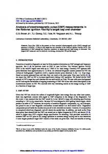
Figure 1.�* � ����������� ���� � �� ���� ���
���� � ������ �� �������� �������������
������#� � ��� �� ���� ���� ��� ���� ���� �� ����� ���� ����� � �� � ����
�� ���� ������ ��� ������ )" ��� ������ � � ���� � ������ �� �� ������ ��� �" ��� �� � ����
�� ���� � � ������ � �� ������� ���� �������� ,�� �� � �� ���� ��� ���� ��� �� � �� ���� ������������������� ������#� � ���� ����
�� ��
� ��� ����� ������ � �������
Figure 3.���������" ��� �� ��
������ � �
�����������������������������������
This is an Open Access article distributed under the terms of the Creative Commons Attribution License 4.0, which permits � ����� �������� distribution, and reproduction in any medium, provided the original work is properly cited.
-./�0�������� ���� ����
2.3 Recuperation unit !��� ���� � �� �� ������������������� ������� ��� �� �� ��
1�������� �� ��������� 8� ������ �����
� � � � �� �����(�� �� �� �
� ���� ���� ���� �� � ����� '���� �� � �������� ��� ���� ��(� ���� �������� ��� �� 9��� �� ������� � �� ����� ���� ��������� �������� 0�� �� � ��� ��:���
� ������ � ����
� � ��� ��� � ����� �� � ����� � � �� ��� �������� ����� ��������� �� �� ��� ���� ���� ��� $����
� ���� ��� ������� ��������� �������
� ����� � �� � ���� ��� ���� ���� ������������ ������� ����� ��� ���������� ��� ����� ������������ ��������� ����� ��� �������������� ��� � � ������������ ����� ���� ����� ���������� ��� $����� ��� � ������� ��� ��� ����� ��� ������ �� ���� �� �� � ��� �� � �� ��� 6��� ;� �� < ��=#� >� ;� �� < ��=�� ���� ������
� ��������� �� ��� ������� ��� �� ��� � ��
� ���� ��� ����� � ����
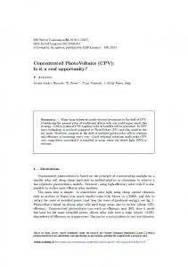
Figure 4.������������ ���� � �� ��
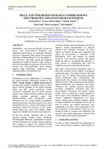
Unit flow Q11 (m3/s) Efficiency η (1)
0,3
3 Development and measurement 3.1. Measurement of turbine
0,2 0,15 0,1 Q11
0,05
η
0 0
10
20
30
40
50
60
Unit speed n11 (1/min)
�
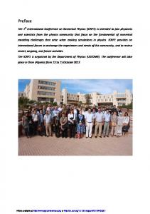
Figure 6.�*� � �� ������� ����� �� ����� � � ���� �� ��� ������
*� � �� ���������(���12�� ����� ����� � ��������������� ����� ����� ���������� ���������
���� 0,08 0,07
Torque Mk (Nm)
1�����
�� ��������� �� ����� �������������� � ��� 2#� � ��� ������� ��� �� � (� �� ������� �#� ���� ���� � � � �� � ����� �� ���� ����������
� �� � ������ ������ ���� �� ���� '��� ����� �� � �� ������� �� ��� ������ � �� ���� ��������� ���� ��� 3 � ���� � ����� �� � �� �� �� � � ��� �������������������(�������� ����������
���� ��#� ���(��� � �� � ���� �� ��������� ����� �� ��� �
�� ��� �� � ���� �� � � �� ������� ���� ������ �� ������ ���� �� � ���� �� ���� ������ ���� � �� �������� �� ����� � � ���� ��������� �� � �� 3 �� �� ����� � � ��� ������ �� �� �� ����� ��
�� '����� �� � ����� ��������� ����� ����������������
������ ����� ���� �� �
� ��� ���
� � (� ��� .�������� �� ����� ���� � �������������� � ������������
0,25
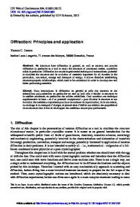
0,06 0,05 0,04 0,03 0,02 0,01 0 0
0,1
0,2
0,3
0,4
0,5
0,6
0,7
0,8
Flow Q (l/s) n = 1000 1/min n = 4000 1/min
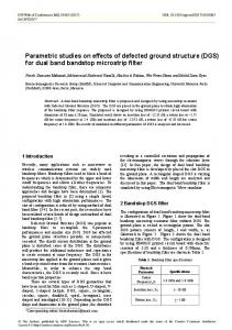
Figure 5.����� �� ����� ��
����� � ��� Table 2. Measured quantities at the turbine. ��
�������� �� ����� �������
.��
5�
�������� ����� � ������
.��
6�
��� �
�+&��
12�
���(���
7��
.����
��� ���
0�
�
� ����
�&��
n = 2000 1/min n = 6000 1/min
�
Figure 7.����(���������� �� ��� � �� ���� ���� ��������������� � ������� �� ������� � ��%�����&� �� �
3.2. Measurement of pump 1�����
� � � ���� �� � �� ��� ����� ��� �� ���� � � �� 2#� � ��� ������� ��� �� � (� �� ������� �#� ���� ���� � � � �� � ����� �� ���� ����������
� �� � ������ ������ ���� �� ���� '��� ����� �� � �� ������� �� ��� � ������ � �� ���� ����������" ��� �� ��3 ������ ����� ��� �� �� �� � � ��� �������������������(�������������������
���� ��#����(��� � �� � ���� �� ��������� ����� �� ��� �
�� ��� �� � ���� �� � � �� ������� ���� ������ �� ������ ���� �� � ���� �� ����
02051-p.2
��������������-'1�5���� ������ ���� � �� �������� �� ����� � � ���� ��������� �� � �� 3 �� �� ����� � � ��� ������ �� ��� �� ����� ��
�� ?� ������� �� ����� ��� ����� ��� ��� � � �� ���� � ����
� � � ���� � � ��� ��� � ����� � ��� ��������� *��� ��� ���� �"�������� ���� (��� ��� ��� �������� �" ��� � ������� ����������
�+*� � �
#��������� � ����������������� ������ �� ����� �� ��+� �� ������#���� ���������� �� ������������
0,7
Efficiency η (1)
0,6 0,5 0,4 0,3 0,2 0,1 0 0
0,5
1
1,5
2
Flow Q (l/s) ��
�
3 blades
5 blades
�
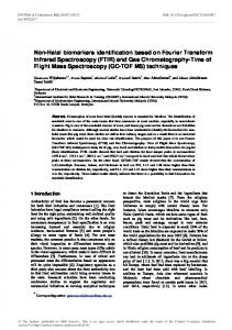
Figure 11.�*� � �� ��������� � � ���� ���� ���
Figure 8.�+#@�������������� � � ������� ���� �������@������
�
�
Figure 9.�)���� ���������������� ����������� � �� ������� ��� ��� �������@������
�
4 blades
.�� ������ ��� ���� ��� ����� @�� ��� ++� ��#� � �� ��� ������� � ����������������� �� ����������� � ������������� �" ��� �� #� �� ������ ����� ��� ��� � � ����� ��������� �� �� ��� �� �� � ���� �������� � ���� � � ��� ��� � ����� �� ���� �� ��
Table 3. Measured quantities at the pump. ��
�������� ����� � ������
.��
5�
�������� �� ����� �������
.��
6�
��� �
�+&��
12�
���(���
7��
�
. �
� ���
0�
���� ���� �� �������++�����
�
� ����
�&��
���
�
Figure 12. !������� �� � �� ������
��� �� ����� ���� � ��
20 15 10
Figure 13. )�:������ �� ������ �����������
�� ��� ��
5 0 0
0,5
1
1,5
Specific energy Y (J/kg)
Specific energy Y (J/kg)
25
2
Flow Q (l/s) 3 blades
4 blades
5 blades
Design parameters
�
Figure 10.�*� � �� ������� �� � ��� �� ��� ���� ��
,���� ������� � ��� ����
� ���� ���������� ��� ���� ��� � � ���������� �� ���������� �������@����� ���@����������
18 16 14 12 10 8 6 4 2 0
Straight part Rotated, in the straight part Rotated, in the elbow without cross Rotated, in the elbow with cross Design parameters
0
0,5
1
1,5
Flow Q (l/s) Figure 14.�*� � �� ������� �� � ��� �� ��� ���� ��
02051-p.3
2
-./�0�������� ���� ����
Efficiency η (1)
0,5 0,4 0,3 0,2 0,1 0 0
0,5
1
1,5
2
Flow Q (l/s)
Straight part Rotated, in the straight part Rotated, in the elbow without cross Rotated, in the elbow with cross
580 560 540 520 500 480 460 0
0,25
0,5
0,75
1
1,25
Turbine flow QT (l/s) Figure 18.�!�� �� ������������ �� ����
Figure 15.�*� � �� ��������� � � ���� ���� ��
5 Conclusion
���������������� �� ��� ������ � �����������" ��� �� � ��� ����������
����� �� ���������� ��������@�����++����� ����� �� � ��� �� ����������� �� �� ���� ���������������� � ������� � � ����� �� ������������������� ��������� �����
���������
4 Recuperation unit 3 ����������� ��� ��� ��� ��������� ����������� �� ���� �� � ��� ���� ����
� �� �� 3 � ���� � ��� � ��� �� ���� �� � � ��� �#� � ��� ����� �� � ���������� ������� �� �������� ���� ��� ������ �� � ��� "����
Figure 16.������� �������� ���� � �� ���
���� �����
� �� �� ��� �� ���� �� � �� ��� ��� ���� ��� � � ����� �� ���� ����� ���� Pump flow QP (l/s)
Pressure losses Pz (Pa)
*� � �� ������ ���������������� ��������� ��� ����� ���� ����� ���� ����� �� ������������ �� ����
0,6
0,7 0,6 0,5 0,4 0,3 0,2 0,1 0
A������ �� ��� � ��� �� ���� �� � �� �� �� � ���� ���� � �� � ��� ���������� ���� ���� � � � �� ��� �"�������� ������ ���� ���� ��� ��� � �� �" ��� ���� �� �� �� ������ � �� ���� ��� ��2�������� ����� � ������������� ���� ����� � �" ��� �� �� ������ �� � �� ��� (� ��� )�����
����������� �������� ���
��������������� +*� � �
���������� �� ���������������� �� ���������� �