Design of Planar Inverted-F Antennas (PIFA) for Multiband Wireless Applications H. F. AbuTarboush1, R. Nilavalan1, H. S. Al-Raweshidy1 and D. Budimir2 Abstract A small three bands printed inverted-F antenna with independently controlling the resonant frequency is presented. The proposed antenna consists of two arms supported by shorting walls fed by 50 Ω microstrip transmission line and a ground plane. The antenna occupied a compact size of 26 x 25 x 3.75 mm. The main radiated patch injected with slot and another arm to generate and control the three resonant frequencies to cover 2.4, 3.7 and 5.2GHz Wireless Local Area Network (WLAN) and Worldwide Interoperability for Microwave Access (WiMAX). The simulated and measured results show that the antenna achieves a gain of 2, 3 and 5 dBi respectively and radiation efficiency of 50%, 60% and 85% for the three bands respectively. The simulated and measured result for the return loss is in good agreements.
1
INTRODUCTION
With the rapid growth of the wireless mobile communication technology, the future technologies need a very small antenna and also the need of multiband antenna is increased to avoid using two antennas and to allow video, voice and data information to be transmitted. The advantage of planar inverted-F antenna (PIFA) makes them popular in many applications requiring a low profile antenna. PIFA antenna is promising to be a good candidate for the future technology due to the flexibility of the structure as it can be easily incorporate into the communication equipments [1]. WiMAX has three allocated frequency bands called low band, middle band and high band. The low band has frequency from 2.495 to 2.695 GHz, the middle band has frequency from 3.2 to 3.8 GHz and the high band has 5.2 - 5.8 GHz. Many researchers have studied different structure and different techniques to increase the bandwidth and to have multiband in single antenna by using double U-slot [2]. Also, by employing two shorting walls to the patch antenna a wider impedance bandwidth has been achieved [3]. A Novel multiband PIFA has been reported for multiband mobile terminals [4]. PIFA for multiband with wide impedance bandwidth is investigated in [5], moreover, a PIFA and PIFLA design is reported recently for dual band operation [6]. Six-band internal PIFA is reported for wireless applications 1
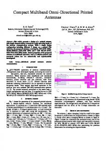
[7]. The approached of controlling the resonant frequencies has been reported in [8] recently, in [8] Planer Inverted-F Antenna (PIFA) was presented to control three resonant frequencies for GSM/DCS/DMB with a total size of 30 x 16 x 9 mm showing a little larger dimension. In all the above designs single and multi bands are achieved by either modifying the shape or by inserting single or double shorting wall to the antenna. The main goals from the previous research work and literatures related with the antenna are focusing on improving the impedance bandwidth performance and controlling the resonant frequencies to cover the needed band. In this paper, a further investigation on the design of Printed Inverted-F Antenna to control three-band by employing two arms supported by shorting walls attached to the edge of the ground plane. This paper aims to decrease the size of the antenna and to improve the radiation performance of the patch antenna in terms of gain, maximum radiation and coand cross polarization. As an advantage of this antenna, resonant frequency can be easily controlled to any targeted frequency between 2 to 6 GHz by either increasing or decreasing some parameters such as, width and length of each arm. The paper is divided as: section two, presents’ dimensions, and configurations of the proposed antenna, section two descript in details the steps of designing three bands PIFA antenna followed by the results. Section three presents the experiential results and finally, section four presents the conclusion. Results are based on a commercially available finite element package HFSS version V11.1. 2 ANTENNA CONFIGURATIONS AND DESIGN PROCEDURE The antenna has a simple structure fed by 50 Ω microstrip line. Fig. 1 demonstrates the dimensions of the proposed antenna used for simulated and experimental study. The dielectric material selected for the design is FR-4 which has dielectric constant
Wireless Network & Communication Centre WNCC, School of Engineering and Design, Brunel University, West London, UB8 3PH, U.K, e-mail:
[email protected], tel.: +447786777851. 2 Wireless Communication Group, School of Engineering, Westminster University, London, W1W 6UW, U.K, e-mail:
[email protected]
L W
Figure 1: The 3D view and detailed diminutions of the proposed antenna
of 4.4 and height of dielectric substrate (h) = 1.57 mm. Generally the overall dimension of the antenna is 25 x 26 x 3.5 mm. The parameters of the proposed antenna are shown in fig. 1. HFSS V.11.4 package is used to obtain the return loss, the gain, the radiation efficiency and the radiation patterns. Fig. 2 shows the simulated S11 of the proposed PIFA antenna. The simulated return loss shows three bands at 2.4, 3.7 and 5.2GHz. The gain for the antenna has value across the bandwidth of 2, 3 and 5 dBi respectively. The proposed antenna satisfies the requirement to cover Wireless Local Area Network (WLAN) and Worldwide Interoperability for Microwave Access (WiMAX) services. Some parameters are affecting the characteristic of the response, the design started with the main radiated top patch which can be calculated by using equation (1), and then rectangular small slot is inserted on the main patch to add another resonant frequency. Arm 2 is added then to generate and control the third resonant frequency as shown in fig.2. Further investigation is carried out in A, B and C to proof the concept of independently controlling the three resonant frequencies generated from the proposed antenna.
4 r
(1)
Where is the wave length, L and W are the length and width of the top plate and r is the dielectric constant. The antenna is fed using 50 Ω microstrip transmission line. The main top patch generates a single band at 2.4 GHz with S11 -18 dB as shown in fig. 2a. It has been found that, different locations of the shorting wall along the X-direction will provide shift of the centre operating frequency. Also it has been found that the operated frequency can be tuned by increasing or decreasing the width and the length of the radiated patch. 2.2 The Effect of the slot on the main patch (Arm 1) As a second step to obtain multi-band, a rectangular slot is applied to the main top patch to generate the second band; the total area of the rectangular slot is 12 x 14mm. The slot has been assigned on the top left hand side to the main patch, it give the shape a look like L-shape which will be called in this paper arm 1. After adding the slot to the main patch another band has been generated at 5.2 GHz as shown in fig. 2b. The 2.4 GHz band is still resonating. By increasing or decreasing the size of the slot, the resonant frequency can be shifted either to a lower or higher band, our target is 5.2 GHz. 2.3 The effect of Arm 2 It is clear from the previous designs the main patch has generated single band at 2.4 GHz, adding a slot to the main patch another band can be generated at 5.2 GHz. Since this paper is to investigate the possibility of generating multi-band from small antenna and controlling the generated band, another arm is added to the structure resulting in generating another band at 3.7 GHz without any changed to the previous 2.4 and 5.2 GHz bands.
2.1 The effect of the main patch The proposed antenna consists of Main top patch, a rectangular slot, shorting pin, shorting wall, arm 2 and a ground plane. The patch is designed separately at first to operate at the WLAN 2.4 GHz band using equation (1), this equation is a very rough approximation which does not cover all the parameters which significantly affect the operational frequency of PIFA. The total size of the main top patch is 20 x 25 mm supported by a shorting wall is attached to the ground plane with height of 3.57 mm. (a)
Figure 3: A prototype of the proposed antenna
(b)
(c) Figure 2: Return Loss response with (a) Main top Patch, (b) Slot (Arm 1) and (c) Arm 2
3 NUMERICAL SIMULATION EXPERMINNTAL RESULTS
Figure 4: The Simulated and Measured return loss for the proposed antenna
AND
In order to validate the simulated results, the proposed antenna has been fabricated. The design was fabricated on FR-4 substrate 4.4 with thickness (h) = 1.57 mm as shown in fig. 3. The frequency responses of the measured and simulated reflection coefficients are shown in fig. 2. A good agreement between the simulated and measured results can be observed confirming that the simulated results obtained with reasonable accuracy. The co and cross polarization for E and H plane radiation patterns at the centre frequencies 2.4, 3.2 and 5.2 GHz are plotted as shown in fig. 5(a)-(c). It can be observed from the radiation patterns, stable response throughout the WLAN and WiMAX bands with low cross polarization. The gain variations are 2 dBi for the first band 2.4 GHz, 3 dBi for the second band 3.2 GHz and 5 dBi for the third band 5.2 GHz. The radiation efficiency for the three is 50 %, 60 % and 85% respectively as can be seen in fig. 6.
-30 -60
0 -10.00 -20.00 -30.00 -40.00
-30
30
-60
60
0 -10.00 -20.00 -30.00 -40.00
30 60
90 -90
-90
90
120 -120
-120 -150
-180
120 -150
150
-180
150
(a) -30 -60
0
0.00 -10.00 -20.00 -30.00 -40.00
-30
30
0
0.00
30
-10.00
60
-60
60
-20.00 -30.00 -40.00
90-90
-90
90
120 -120
-120 -150
-180
120 -150
150
(b)
-180
150
-30 -60
0
0.00 -10.00 -20.00 -30.00 -40.00
30 60
-90
0
0.00 -10.00 -20.00 -30.00 -40.00
-30 -60
60
90 -90
-120
90
120 -120 -150
-180
150
References
30
120 -150
-180
150
(c)
Figure 5: X-Y, Y-Z Radiation patterns at (a) 2.4GHz (b) 3.7GHz (c) 5.2 GHz
[1] P. S. Hall, E.Lee, C. T. P. Song, Planar Inverted-F Antennas, Chapter7, Printed Antennas for wireless Communications Edited by R. Waterhouse, John Wiley & Sons, Ltd, 2007. [2] H. F. AbuTarboush, H. S. Al-Raweshidy, R. Nilavalan, “Triple Band Double U-Slots Patch Antenna for WiMAX Mobile Applications”, 14th Asia-Pacific Conference on Communications, Japan, pp. 1-3, 2008. [3] Chi Yuk Chiu, Chi Hou Chan and Kwai Man Luk, "Study of a small wide-band patch antenna with double shorting walls," Antennas and Wireless Propagation Letters, IEEE, vol. 3, pp. 230-231, 2004. [4] R. A. Bhatti, Young Sin Shin, Ngoc-Anh Nguyen and Seong-Ook Park, "Design of a Novel Multiband Planar Inverted-F Antenna for Mobile Terminals," Antenna Technology: Small Antennas and Novel Metamaterials, 2008. iWAT 2008. International Workshop on, pp. 530-533, 2008.
Figure 6: The radiation efficiency for the three bands
Frequency (GHz)
2.3
3.7
5.2
Gain (dBi)
2
3
2
Table 1: The max. gain for the three bands
CONCLUSION A Novel compact multi-band Printed Inverted-F Antenna has been designed and fabricated to independently control WLAN and WiMAX bands. The antenna can be used as single-band or as multiband. Although the antenna has been design to operate in WLAN and WiMAX, it would also be possible to design the bands to any other system by changing the length of the top patch, the width of the slot and the width of Arm 2.
[5] Dong-yeon Kim, J. W. Lee, Choon Sik Cho and T. K. Lee, "Design of a Compact TriBand PIFA Based on Independent Control of the Resonant Frequencies," Antennas and Propagation, IEEE Transactions on, vol. 56, pp. 1428-1436, 2008. [6] Hoon Park, Kyungho Chung and Jaehoon Choi, "Design of a planar inverted-F Antenna with very wide impedance bandwidth," Microwave and Wireless Components Letters, IEEE, vol. 16, pp. 113115, 2006. [7] C. H. See, R. A. Abd-Alhameed, D. Zhou and P. S. Excell, "Dual-Frequency Planar Inverted F-L-Antenna (PIFLA) for WLAN and Short Range Communication Systems," Antennas and Propagation, IEEE Transactions on, vol. 56, pp. 3318-3320, 2008. [8] Yong-Xin Guo and Hwee Siang Tan, "New
compact six-band internal antenna," Antennas and Wireless Propagation Letters, IEEE, vol. 3, pp. 295-297, 2004.