Michael Freeman, Chris Bailey. University of York, UK. ABSTRACT. In this paper the development of ubiquitous computing applications is investigated, from ...
DESIGNING A UBIQUITOUS COMPUTING DEVELOPMENT KIT Michael Freeman, Chris Bailey University of York, UK
ABSTRACT In this paper the development of ubiquitous computing applications is investigated, from initial micro-controller based prototypes to application specific FPGA based systems. The aim of this work is to add additional capabilities to every-day objects, allowing them to sense their environment and interact with the people and objects within it, to enhance their existing functionality. To achieve this we have developed a micro-controller based, ubiquitous computing development kit (UcDK), allowing researchers to rapidly construct and evaluate different ubiquitous computing applications. In addition to this, we are developing component technologies for future pervasive computing environments. This has lead to the construction of an application specific processor and other IP cores to meet these needs.
1. INTRODUCTION Developments in ubiquitous computing have lead to the concept of disappearing computing [Wejchert, 2000], with a user being unaware that they are interacting with a collection of computing nodes. The aim of this technology is to add additional capabilities to every day objects, allowing them to sense their environment and interact with the people and objects within it, to enhance their existing functionality. Such devices have been termed context aware applications [Schmidt, 2001], smart devices that sense the real world they are operating in and use this information combined with a set of rules to enhance their operation. These objectives require that computing technology is seamlessly integrated into an environment. This has become a reality with the ever decreasing cost, size and power requirements of embedded processors. However, an alternative approach to this traditional processor based solution is considered in this research. Instead of using a general purpose processor, a more hardware biased solution is taken, with the development of application specific IP cores for FPGA or ASIC devices that can be optimized for a desired application. The main aim of this approach is to minimize power requirements and component costs by designing system on a chip (SOC)
based systems. Ubiquitous computing applications require the following functional units: communications, processing and interfacing. These functional units are now implemented as hardware components written in VHDL. A designer would select the desired components dependent on the required application e.g. a light controller would require a communications unit, an external interface to control the TRIAC or relay used to switch the bulb, but may only require minimal processing capabilities due to the small system state and number of operations. This ability to scale a design to match an application allows smaller ASIC / FPGA devices to be used, minimizing cost and power requirements. In addition to this, each hardware component can also be optimized for speed, size and power considerations, giving a designer greater flexibility in distributing the required processing capabilities amongst the selected components. When the desired components have been chosen and optimized, they will be combined to form a SOC architecture. The choice of system bus will again be dependent on the desired application and its required processing performance, size, cost and associated power requirements. In section 2 we will introduce a ubiquitous computing development kit (UcDK). This kit is constructed from a number of modular boards based on a small footprint 8051 micro-controller, allowing researchers to rapidly construct ubiquitous computing applications. These modules are connected together via serial communications buses, to form a linear array of processing blocks. Data or functionality can be requested across this bus to achieve the desired system functions with only minimal software alterations. This solution is significantly faster than traditional approaches, allowing an initial prototype system to be evaluated in the field, before a complex SOC design is implemented. Its other main role is a means of capturing the requirements and, therefore, the hardware components (IP cores) for typical ubiquitous computing applications. Allowing initial development work produced in the micro-controller based prototypes to be easily integrated into a final SOC based solution. In section 3 we describe a front door demonstrator that has been used as an initial case study to capture the system functions found in a typical ubiquitous computing scenario. This leads onto a discussion of the communication, power and user interface requirements. Finally, we close this paper with conclusions and future work.
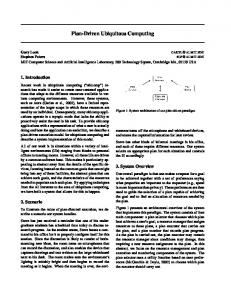
Figure 1. An intelligent light controller application
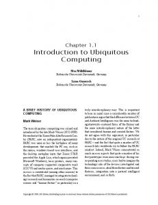
Figure 2. Cooker hob wireless interface
2. UcDK : UBIQUITOUS COMPUTING DEVELOPMENT KIT The UcDK contains a range of micro-controller based modules designed to be interconnected to achieve the desired functionality. The novel feature of this kit, compared to previous designs, is its hardware biased solution to the problem of rapid prototyping this type of system. The UcDK differs from previous designs [Beigl, 2002] in that the modules in this kit are categorised by their function i.e. data link, data logging etc, and not by their physical components i.e. processor board, IO board etc. The intended design approach is to select the required hardware modules to achieve the desired functionality and connect these together using bi-directional serial communications links. These simple serial communications interfaces allow the UcDK to be easily
expanded if the desired functionality cannot be obtained from the existing boards. The aim of this approach is to minimise software and hardware development times, by separating commonly required functionality into stand alone modules. At present the UcDK contains 17 hardware modules, each measuring 67mm x 52mm. The boards within this kit are classified as either: • • •
Communications : low bandwidth radio, directional and omni-directional infra-red links. Processing : application specific processing modules e.g. data-logging, ADC sensor, digital I/O controller, serial port hub controller etc. Interfacing : external system buses, signal isolation / drivers, mains power supply, battery controllers.
The communication and processing boards are implemented using Atmel 89C2051 / 89C4051 microcontrollers [Atmel, 2001]. This micro-controller is based on
a standard 8051 core, with up to 4K of ROM and 128 bytes of RAM. Data is passed between these boards using the on-chip serial ports. At this time the UcDK has 3 communications boards based on infra-red and radio modules. The most commonly used board is the radio data link: •
Radio board : omni-directional data link, based on a Radiometrix BiM2 433MHz bi-directional radio module, onboard antenna, allowing 1200 – 19.2K bps.
The radio board also has an I2C port for peripheral expansion, 2 low resolution ADC channels, real time clock and up to 11 general purpose IO lines. This module has been used for a number of simple applications, having sufficient hardware resources to allow it to be a single board solution if required. An example of an application developed with the system is shown in figure 1. This is an intelligent light controller, processing sensor data from an analogue light sensor and a passive infra-red sensor, allowing this controller to turn a light on if a person is detected in a dark room. The real time clock is then used to turn the light off if nobody is detected for a pre-defined time out. The light can also be turned on and off using a push button or by commands sent over the radio link. In addition to these features, pre-emptive control of the light’s behaviour can be included. Using the real time clock, the typical usage of the light for each day of the week can be recorded, allowing the light to be turned on a few minutes in advance of its typical requirements. If this example is now viewed in a wider context, each light controller is capable of recording the activity in a room e.g. when were people moving about, sitting down etc. This information can be shared with other devices via the radio module, allowing them to combine this information with local sensor data using rule sets to enhance heir operation. When more complex functionality is required, additional processing boards can be added to form a linear array of processing modules, with data passed between modules using serial data buses. Typically, the head node within this array is the master node requesting services from the remaining slave nodes. The UcDK has five main processing boards, again based upon an Atmel 89C2051 micro-controller with an I2C port for peripheral expansion, 2 low resolution ADC channels, real time clock and general purpose IO lines. In addition to these basic functions each board includes specialized components: • • •
CPLD board: XC9572 CPLD, up to 34 GPIO lines, micro-controller data link via a SPI interface. Data logging board: up to six 32K byte EEPROM or 256 byte RAM, I2C memory devices. General purpose processing board: 4 channel I2C ADC, 1 DAC and RS232 line driver.
• •
Digital processing board: equipped with two PCF8574 devices, allowing up to 30 digital IO lines. Analogue processing board: equipped with two PCF8591 devices, allowing up to 10 ADC and 2 DAC channels.
Figure 2 shows another test application, using a twoprocessor array to add ubiquitous computing capabilities to a cooker hob. A digital processing board (right) is connected to the hob’s internal seven segment display data bus. The state of each ring and the timer can now be monitored. This state information is sent to a radio board (left) via a serial link, allowing external devices to access this data (the radio board is mounted remotely to minimize interface from the hob). The cooker hob application demonstrates the aim of the UcDK of separating functionality into separate boards to simplify system level development, minimising software and hardware development times and debugging. A number of kitchen based applications have been developed using the UcDK e.g. cooker, hob, fridge, washing machine. These are being developed as part of the York Responsive Home, led by CuTech [Cuhtec, 2004] which is aimed at evaluating ubiquitous applications in a domestic context. As a result of these experiments, an understanding of the requirements for these types of applications has been obtained and used in the development of IP cores that are used in FPGA based, SOC designs. Following the work produced using the UcDK, a number of common system requirements have been identified. This functionality has been converted into matching hardware cores, to allow a FPGA based system to be developed, examples of which are shown in table 1. To minimize development times we would like to reuse as much of the software developed in the initial UcDK prototypes as possible. A design flow to allow this is shown in figure 3. This example is based on the cooker hob example shown in figure 2. Initially a micro-controller based UcDK prototype is constructed (figure 3a). To maximize software reuse, the simplest approach to migrate this design into a FPGA is to replicate the 8051 cores used in the UcDK modules within the FPGA (figure 3b). This minimizes software alterations, but at the cost of increased hardware requirements. Therefore, the final stage of this design flow is to replace low-level software functions with dedicated hardware modules (figure 3c) e.g. radio controller etc. This maintains the top level software architecture, but reduces the processor loading, allowing a single 8051 processor core to be used. To allow the design flow shown in figure 3 to be used, requires a processor core that is capable of executing the 8051 instruction set. However, existing 8051 compatible cores require a significant percentage of a small FPGA’s resources. This relatively large size is due to the 8051’s
size and cost of the required FPGA device. This processor can also take advantage of a microprogrammed controller’s ability to execute different instruction sets. The controller’s instruction decoder and microcontrol memory can be modified to allow this processor to execute a variety of ISA, removing the need to develop specialized software tools. The size of this processor is further reduced by only supporting those instructions required by the application i.e. the instruction decoder is edited, removing instructions that are not required; microcontrol memory is not altered since it is a fixed dedicated resource. Future versions of this processor will be tuned to support the particular requirements of embedded processor applications.
architecture not mapping efficiently onto the FPGA’s resources, i.e. bit addressable memory, highly encoded instruction set etc. When these cores are combined with other IP cores required to implement the desired system, a medium sized FPGA would probably be required, with its associated increase in cost and power consumption. Therefore, an alternative approach was taken, the development of a minimal complex instruction set computer processor (MCP) core [Freeman, 2004]. This processor core achieves very low area requirements by using micro-code to emulate the 8051 instruction set. Implementing microcontrol memory in dedicated block RAM storage elements reduces the amount of general purpose logic required by this processor core, reducing the
Table 1. Example IP-Cores
RAM
RAM
RAM
(a)
(b)
(c)
Figure 3. A typical development design flow
3. FRONT DOOR DEMONSTRATOR
alterations. The door demonstration, shown in figure 4, has five ubiquitous computing nodes :
The intent of this demonstrator is to further investigate and show how the UcDK can be used to quickly develop an ubiquitous computing scenario. Micro-controller based modules can be quickly combined to achieve the desired functionality with minimal software or hardware
Base Station (top left) : contains three UcDK modules; radio comms., infra-red comms. expansion and RS232 driver boards. These allow the radio and infra-red comm. networks to be connected to the internet or existing home networks via a PC or Ethernet-to-RS232 adaptor. In the present configuration the infra-red and radio networks use
the same five byte packet format, allowing approximately 16K nodes to be addressed, using a 16 bit data word and 8 bit checksum. At present 8 packet types have been identified : Get Status, Set IO, Get IO, Get ADC, Set RTC, Set Event, IR router. Lock & Alarm Node (middle left) : contains three UcDK modules; radio comms., low voltage relay and infra-red sensor boards. These allow the alarm and magnetic door lock to be controlled remotely. Also the state of the door; open or closed indicated by the infra-red sensors and these actuators can be accessed across the radio link. The door lock and alarm outputs are configured in a pulse mode, so that when these outputs are enabled they will be reset to an inactive mode after a predefined time. Daily or single output events can also be configured across the radio e.g. un-locking the door during office hours etc. SOC FPGA Node (bottom left) : contains two UcDK modules; radio transceiver and voltage shifter boards. This node is based on the ubiquitous system explorer (USE) board developed by the Amadeus centre. The USE development board uses a Xilinx Virtex II FPGA, with on board PSU, flash and CPLD configuration engine, allowing truly embedded operation. A number of memory e.g. SRAM and SDRAM, and interface boards e.g. level shifter 3.3/5V, have been designed to allow initial UcDK micro-controller based prototypes to be replaced by FPGA SOC designs based on matching IP-cores. Light & Doorbell Node (top right) : contains three UcDK modules; radio communications , mains voltage relay and infra-red communications expansion boards. These allow the light and doorbell to be controlled remotely. Also the light level can be read by the on-board ADC and the status of these actuators can be accessed across the radio link. The door light output is configured in a latching mode, requiring a reset command to be sent to the radio node to de-activate the light. The doorbell switch is read by the micro-controller and its signal de-bounced in software, allowing the doorbell button to be remotely disabled. Daily or single output events can also be configured across the radio e.g. turning the light on during the hours of darkness. This node also acts as a router node allowing the radio network to be expanded with the inclusion of a number of infra-red communication modules i.e. the passive infra-red and signal light node. PIR Sensor & Signal Light Node (middle right) : contains two UcDK modules; infra-red comm. and open collector driver boards. These allow the red and green door status lights to be controlled remotely. Also the state of the passive infra-red sensor and the status of the actuators can be accessed across the radio link. The door status light outputs are configured in a pulse mode, so that when these outputs are enabled they will be reset to an inactive mode after a predefined time. The infra-red comm. board
controlling this node can be used in its own right to construct a cheap, low bandwidth, directional prototype network. Alternatively they can be used to increase a radio comm. based network by allowing each radio nodes functionality to be expanded with a number of local subnodes e.g. short range wireless network. The control and state of these nodes are integrated into a central database via the base station, using a remote procedure call (RPC) communications protocol. From work on the demonstrator, the following system functions relating to this protocol were identified : •
• •
• •
Get status : returns the number of specified events, type and time stamp, that have occurred since the last request. Additional memory required to log these events can be minimized by filtering or combining events that occur within a specified time interval. Using this approach minimises the required communications bandwidth, simplifying the systems network. Set IO : sets output control lines or internal register values on a node. Data field is specific to each node type, defining data destination and packet length. Get IO : returns the status of input control signals, ADC, or internal register values on a node. Data field is specific to each node type, defining the data source and packet length. Set real time clock : this packet can be sent to individual nodes or as a broadcast packet, setting the current day, hour and minute values. Set Event : each node can be configured to perform eight events i.e. actions to be performed on specified days and time. Data field is specific to each node type, defining event action.
Integrating these commands into the existing communications protocol allows the status of each node to be monitored and its actuators to be controlled by a web browser interface [Mckay, 2005], as shown in figure 5. (using an Ethernet to serial converter [Moxa, 2005]). This data is also logged in a central data base, allowing nodes to adapt their operation in response to external events. For mains powered devices the existing polled communications protocol, using simple handshaking and CRC error detection is sufficient, however, this approach requires significant electrical power. Communications and therefore power usage can be minimised to some degree by using: • •
Distributing limited control where possible: combining a sequence of command packets into a new RPC. Real time clock (RTC), triggering daily or repeated events: certain broadcast and periodic command
•
•
packets can be replaced by a single specified RTC triggered event. Programmable Latched / Pulsed outputs: multiple on / off output command packets can be replaced with a pulse + duration, or, complex predefined waveform command packets. Input logging (sensor data) + time stamp: minimizes protocol overheads by sending an event log for specified events. The size of this data packet can be further reduced by filtering or combining events that occur within a specified time interval, minimising bandwidth.
However, to maximise the life of battery powered devices, each node must be powered down for a significant percentage of the time. The Atmel’s Flash microcontrollers have two software-invoked power reduction modes: •
•
Idle Mode. The CPU is turned off while the RAM and other on-chip peripherals continue operating. In this mode, current draw is reduced to about 15% of the current drawn when the device is fully active. Power Down Mode. All on-chip activities are suspended, on-chip RAM retains data.
Figure 4. A front door demonstrator
Figure 5. GUI Screen shoots
These microcontrollers are designed using static logic, which does not require continuous clocking. Therefore, another approach that could be used to reduce power requirements would be to slow or even stop the system clock whilst waiting for an external event. Using these power saving techniques, each node will periodically power up (presently controlled by the on-chip timer unit), log sensor data and check if a radio signal is present (carrier detect on the transceiver module). If a signal is detected the node will remain powered up to process the communication packet, otherwise, it will power down until the next time period. Consideration of output signal encoding can also minimise power wastage from pull-up resistors and drive stages. These modifications to the existing UcDK, significantly improve battery performance. Further improvements will have to come from a change in technology, however, for the purposes of this kit, it is hope that these modification will be sufficient for most applications.
4. CONCLUSIONS An ubiquitous computing development kit has been designed in order to allow rapid prototyping of embedded processor applications. The design emphasis for this kit is to minimise software and hardware development times by using a number of application specific software / hardware modules and IP cores. Using this technique an initial prototype can be rapidly constructed by connecting existing modules e.g. radio communications, data logging, analogue sensor boards etc. together via a serial communications bus. Data or functionality can be requested across this bus to achieve the desired system functions with only minimal software alterations. This solution is significantly faster than traditional approaches e.g. designing a new PCB and software architecture for each application, as each hardware and software component is considered in isolation. This minimises the number of software alterations and processing constraints (memory and real time processing performance) for each component. By developing an initial prototype a system can be evaluated in the field to check its operation and identify possible improvements. The next stage of the design process is to match this micro-controller based system to the equivalent IP-Cores within the existing library, allowing a SOC FPGA based system to be implemented. This approach again minimises development times as an indication of required FPGA resources can be quickly determined and an equivalent SOC version implemented. To maximise software re-use from the initial micro-controller based prototype a minimal CISC processor core has been developed. This was required, as existing 8051 processor cores require a large amount of
the FPGA’s resources. The MCP core offers a 80% reduction in area, freeing this general purpose logic for peripheral devices, minimising FPGA cost and power requirements. To further develop this kit and increase understanding of ubiquitous computing applications, a door demonstrator has been constructed. Future work will focus on developing software and hardware architectures to support this demonstrator, in particular the web page interface and data base software structures. This will allow high level rule based schemes to be implemented, further improving the functionality and operation of the nodes within the system.
5. ACKNOWLEDGEMENTS The work presented in this paper was supported by the DTI Next Wave Technologies and Markets programme, as part of the AMADEUS virtual research centre. The cooker hob was donated by NEFF.
REFERENCES Atmel, (2001), 8-bit microcontroller with 4K bytes flash : AT89C4051, WWW: http://www.atmel.com Beigl, M., Zimmer T., Krohn A, Decker C., Robinson P., (2002), Smart-Its – communication and sensing technology for UbiComp environments, WWW: http://ubicomp.teco.edu/publ.html CUHTEC, (2004), The Centre for Usable Technology, WWW:
http://www.cuhtec.org.uk Freeman M., (2004), "A Minimal CISC Processor Architecture for Field Programmable Gate Arrays", Euromicro Conference /DSD Symposium 2004, Work in Progress Session, Rennes, France Schmidt, A., Van Laerhoven K., (August 2001), How to Build Smart Appliances? IEEE Personal Communications 8(4), pp. 6671. Mckay I., (2005) Ubiquitous Intelligent Home : Building the foundations, MSc project, Dept of Computer Science, York University. Moxa, (2005), Modbus Gateways : Nport 6110, WWW: http://www.moxa.com/products/Modbus_Gateways.htm Wejchert, J., (February 2000), “The Disappearing Computer”, Information Document, IST Call for proposals, European Commission, Future and Emerging Technologies., WWW: http://www.disappearing-computer.net/mission.html