a behavior of this kind, they would need to add a SDVVLYH component .... Integrity cannot be restored neither by writing new headers nor by adding footers.
Detecting and Solving Architectural Problems with JACALA Nicolás Kicillof and Daniel Yankelevich Departamento de Computación Facultad de Ciencias Exactas y Naturales, Universidad de Buenos Aires I Q L F R N � G D Q \ J# G F � X E D � D U
Abstract. A modern application is made of many interacting components establishing different types of connections between them. Software architectures are a level of description dealing with the overall structure of a system and, specially, with the way its constituent parts interact. The intended architecture of a system is usually devised during the design stage, having in mind a dynamic model. In this work we present a language called JACAL (with a graphical notation) that can be used to represent a system’s architecture together with its dynamic model. We then explain how a software application was developed that allows a user to draw a JACAL specification and then run it. This execution exposes the behavior of a system in terms of the interaction of its components in order to help avoid further development on a bad design. Finally, we introduce an example to illustrate how the tool can be used to detect errors in the architectural conception of a system and to test a possible solution. Keywords: software architecture, language, JACAL, ADL, architectural problems, detection, solution.
1 Introduction As protocols and standards for communication between processes running on the same computer or distributed over a network have become widely available, the nature of software systems has also changed. Nowadays, the building blocks of a system are no longer pieces of code that are linked together to yield a monolithic executable program. A modern application is made of many interacting components, often running on multiple platforms establishing different types of connections between them and with the rest of the world. Not only is source code reused as part of more than one system, but a single instance of a process or module is usually shared by several applications. Of all the stages of software development, the design stage is probably the one most affected by these changes in technology. The design problem goes now beyond algorithms and data structures; it now deals with determining what the overall system organization will be [9]. A designer must be concerned about issues such as gross-level decomposition of a system into interacting subsystems, assigning functionality to each component, protocols used in communication, synchronization and data access, physical distribution, interoperability and performance. This level of description for software systems is called the software architecture level. Software architectures are usually represented as a collection of components and connections between components [1]. Additionally, a set of constraints must be given, to help determine whether a particular system conforms to an architecture [19]. These constraints are often made explicit, expressing them in a more or less formal language. In some cases, constraints are implicit in the semantics associated to the symbols used to represent components and connections. The purpose of this work is to introduce JACAL: a tool created to help designers understand how a system based on a particular architecture will behave. This tool consists of an architectural description language and a desing environment. The JACAL design environment builds, out of the description of a software architecture, a working prototype that can be used to model the concurrent execution of its components. B Partially
supported by grant UBACYT EX-186
1
Finally, an example shows how the use of the tool can help a designer in the detection of design errors. Without these techniques, such errors, often concerning concurrency and synchronization, might surface after system deployment when they can seriously affect system functionality. Their correction usually requires going back in the development process as far as the design stage. Our idea of executing a system at the architectural level is very different from formal verification of properties. With the tools we provide, a designer can observe the behavior of a system based on the currently proposed architecture and compare it with the expected behavior for the final product. Anomalies can be detected through this procedure which would not even be sought for when testing for formally enunciated properties.
1.1 Related work Being software architecture a rather new discipline, a specific notation has not yet emerged as a standard. Many proposals have been made to fulfill this need: Wright [2, 3], CHAM [14], Unicon [25], Rapide [17], Aesop [8], ACME [10], and historically GDN and TDN [13]. Other notations are not intended to serve by themselves to describe a system’s architecture. They are limited to one aspect of the description and need to be combined with other notations to represent a whole architecture. Such is the case of extended event traces ([6]). There’s not even a universally accepted convention establishing the requirements a specific notation must fulfill to be considered an architecture description language (ADL). Nevertheless some considerable efforts have been made in this field [18, 24, 20]. Researchers are always confronted with the choice between using one of the existing languages or creating a new one [5, 16]. The problem with the latter option is that it increases the noise in an already overpopulated ground. It should only be chosen in the case where all other possibilities have been considered and discarded. From the beginning, our goal has been to build a tool that could be used to edit a system’s architecture and then graphically simulate its behavior. This goal led us to an enumeration of some basic properties the chosen language must have. The following is a reduced list of these features: Behavioral information. A strong hypothesis of this work is that, while planning a system’s architecture, the designer has in mind a dynamic model of the system, and that some of the properties expected to hold in this model can be tested before the software development process goes beyond this initial stage. Therefore, a language for software architectures should allow the designer to represent enough information for this testing to take place. Formal semantics. Mere translatability of an architecture into an execution model such as a programming language does not solve every problem posed by lack of precision (even when the programming language itself has a well-defined semantics). This approach limits the expressiveness of architectural description to just those structures supported by the target implementation language while obscuring the intent of the designer [1]. The alternative is to choose an architecture description language with a formal semantics of its own. The function mapping an architecture to its meaning should be as close as possible to a biunivocal correspondence, and the resulting model should have a close resemblance to the language itself. Graphical notation. This is a natural and widely used way for communicating high-level architecture descriptions [4]. The possibility to graphically simulate the behavior of the system makes this item highly attractive for our project. The designer should be able to actually see the system work as if the same picture that was used to depict it came alive. Connector types. Another reason why some languages were discarded is their lack of focus on connector types. This feature, considered crucial by theoreticians [4, 20], provides constructs to define connectors and their semantics, separately from components. This allows the designer to encapsulate well-known communication patterns inside language constructs, instead of representing them as unique components of a particular system. A set of pre-defined connector types is also desirable in order to compare different architectures. Understandable syntax. A major role of architectures is to facilitate understanding of systems at a high level of abstraction. This is why we require an ADL to model structural information with a simple, understandable syntax, where system structure is clear from a high-level specification of its configuration [20]. We decided not to use languages where configuration descriptions are specified in-line, because they would jeopardize the ability of a designer to draw overall conclusions from the simulation of system’s behavior. 2
Unfortunately, none of the languages proposed in the literature satisfy all the listed criteria. The decision was thus taken to create a new language including those features. This approach provided the additional benefit of using a language strictly conceived for the purpose of this work, avoiding the need for the design environment to support unwanted features just to comply with the chosen language specification.
1.2 Overview The reminder of the paper is intended to portray the JACAL language and the application that transforms architecture descriptions written in JACAL in working prototypes of systems conforming to those architectures. Section 2 contains a description of the basic features of the language and an introduction to its advanced features (considered beyond the scope of the paper). The formal semantics of JACAL is given in Section 2.3. Section 3 explains how a software tool was developed to implement the JACAL editor and behavior simulator. Sections sec-problem and sec-solution show an example of design problems detection and solution using this tool for a very simple case study.
2 JACAL Language JACAL is just a compilable architectural language. It was introduced in [15] to be used mainly as a notation in the early stages of a software development process, which can also be compiled to yield a high-level prototype of a system. It is not intended to serve as a powerful tool for describing static properties of software systems. It yields a running prototype exposing the dynamic behavior of the different parts composing the system in order to help avoiding further development on a bad design.
2.1 Basic Features The basic portion of JACAL features two levels of description: G
The first (high) level shows what components the system has, what their interfaces are and how communications between them occur. It is a design notation in the classical sense, but it is not sufficient by itself for expressing when and how one of these communications triggers others.
G
The second (low) level is where the actual behavior of a model is portrayed. When a component receives some input from another, its internal state usually changes. In addition it might, in turn, send other signals to one or more components. Although these dynamic properties are not always considered to be part of an architectural view of a system, they are necessary to achieve our goal. No simulation would be possible if we had only a static, relational description.
2.1.1 Interface Level The interface level is where the configuration of a software architecture is represented. This level defines components, sockets and links. The behavior of the architecture is only implicit in the link and component types chosen by the designer as building blocks. Only two pieces of information are given about a component: its type and its interface. The interface is a set of input and output sockets to which links are attached. Output sockets must appear in at most one component’s interface whereas input sockets can be used by more than one component. Component types act as constraints on the contexts in which a component can be used. A few examples will be presented, although this taxonomy is not intended to be exhaustive but to be simple and sufficient for a first approach. The attributes of a link are the same as those of a component, that is its type and its interface. The interface of a link is given by the pair of sockets it links, the order of the pair representing the direction in which the information flows through the link. Alternatively, one (but not both) of the elements in a link’s interface may be blank (z ), meaning an interaction of a component with the outer world. A z for the destination of a link means
3
a component (the owner of its source socket) issues a message to a user (or another system, not included in the architecture being described), and a z for the source means a component (the owner of its destination socket) receives input from outside the system. As with component types, link types have been pruned for the sake of simplicity. Unlike component behavior (described in the language’s lower-level), link behavior is implicit in link types. This is why a subset of the language, no matter how simple, must include several link types in order to be useful to present a case study. Each link type has an associated arity. The arity of a link is a binary relation on the set of all possible component types. By defining the arity of a link type, one can restrict the contexts in which a link of that type may be used. In the following list, arities are not explicitly given. In fact, arities for link types are implicitly declared in the definition of component types. For example, stating that component type $ can be connected to components of type % by a type F link, would imply that K$ �% L is a member of the arity of F . Here we give an intuitive idea of the behavior of each link type. As explained above their formal semantics will be explained in Section 2.3. FDOO�
Transfers control and waits for a result to be returned.
PHVVDJH�
Places the message in a queue and continues execution.
LQWHUUXSW�
Interrupts any current control flow in the receiving component and waits for a result.
IRUN�
Adds a control flow to the receiver, the sender keeps running.
NLOO�
Kills any control flow in the receiver. The sender keeps running.
GDWDJUDP�
If the receiver is waiting for a communication through this link, the message is received; otherwise, it’s lost. In any case, the sender keeps running.
UHDG�
Execution in the sender continues, according to the receiver’s state.
ZULWH�
Changes the state of the receiver, the sender keeps running.
As it should be clear by now, component types are used in combination with link types arity in order to constrain the set of architectures that can be built. A storage device, for example, should not receive a control flow (although its driver might) because such a design could never be implemented. This distinction between components being able to execute and others whose state can only be modified from the outside has been considered fundamental when choosing a set of component types as simple as possible. QRQ�UHHQWUDQW�
Does not accept
FDOOV, IRUNV
(maintains a unique control flow),
UHDGV
or
ZULWHV.
SDVVLYH�
Only accepts U H D G V and Z U L W H V . Every state change of a passive component must be performed by another (non-passive) component. Their state can not change via transitions (transitions not visible from the outside).
UHHQWUDQW�
Does not receive U H D G V or Z U L W H V . Although not likely, an L Q W H U U X S W could be issued to a reentrant component (this would model the action of an ill behaved component performing a destructive action like, for example, moving the code of the receiving component to a new memory location before transferring control).
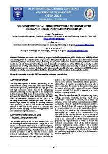
Figure 1 introduces the graphical notation of JACAL. This notation is intended to be the only syntax for JACAL. New component and link types should also be given a graphical representation in order for the language to be smoothly extended.
2.1.2 Behavior Level At the lowest level, components are represented by place-transition nets, with labeled transitions. Every transition in these nets is of trivial nature, consuming one token from a source place (state) and sending one token to a 4
Figure 1: Links and components destination place. We therefore simplify their graphical representation by replacing both arrows and the transition symbol with a single arrow from the source to the destination (see Figure 2). A transition can be labeled with a socket name meaning the component must send or receive a communication through the socket for a control token to cross this transition. Q transitions are transitions without a socket name in their label (i.e. not involved in an interaction with other components). A prime ( ) can be appended to the end of the socket name to denote a reply (i.e. a return of control flowing through a link in the direction opposite to the link’s own).
Figure 2: Representing transitions For each input socket of a F D O O , L Q W H U U X S W or I R U N , the component must contain a corresponding unique initial state (a root node). No other node in the component can be the source of a non-return transition associated with that link. Control flows received will begin execution in the initial state. In the case of F D O O V and I R U N V this is independent of other flows the component might eventually have. The reason for this is that non-passive components do not have a global internal state (shared by all control flows). Should the designer need to model a behavior of this kind, they would need to add a S D V V L Y H component accessed by transitions in the mentioned active component.
2.2 Advanced Features In Section 2.1 we only described the features of the JACAL language that we consider essential to understand how the software environment can be used to solve certain design problems. Nevertheless, JACAL was created as a multipurpose, extensible ADL. The following list is a summary of the features left out of the basic description. [15] should be consulted for an in-depth explanation of each item in the list. Component type hierarchy. Component types can be organized in a hierarchy. A mechanism for inheritance allows components of one type to gracefully replace components of a supertype. This tool is useful when applying succesive refinements to an architecture in order to produce a more accurate description of the intended system. Implicit invocation. Using only the features described in Section 2.1 restricts the user to specify at design-time which component will act as the target of each communication. A syntax to represent events adds the
5
ability for components to become event handlers at run-time. When an event is raised, only components registered to handle it receive the corresponding communication. Multicast. One-to-many links are used to represent multicasts. An alternative would be to replace a multicast by a collection of links between the sending component and every receiving component involved in the communication. The problem with this approach is that in the latter case an order should be chosen for these communications to take place. On the other hand, our approach denotes a non-deterministic behavior, even if an interleaving semantics is assumed. Return parameters. Simple data can flow from the target to the source component of a link so that further execution in the latter can depend on the state of the former. This is not a complex parameter-passing scheme as the ones provided by programming languages. It is just a way of extending the expressive power at the architectural level. Time. Time tags can be added to transition labels in the behavior level. A minimum time means the transition can not complete before that period of time elapses, even if all other constraints are fulfilled. A maximum time only makes sense when accompanied by a port name. If a communication through that port is not achieved (or completed) before the maximum time, the transition will succeed anyway. This feature of the syntax must be accounted for in the semantics. Several proposals of extensions to Petri nets have been made in order to add to them the capability of expressing time [11, 12].The translation from JACAL to the chosen model is straightforward. Platform level. Part of the non-functional information that usually guides a designer planning an architecture cannot be described in the two levels introduced so far. Examples of this kind of constraints are whether two components will be located on the same site (LAN) or the communication protocols over which the links will be implemented. We call this kind of information the platform level. JACAL offers two ways (one informal and one structured) to add this information to an architectural description. Graphical representation extensions. As explained in Section 2.1.1, the sole notation for JACAL is graphical. All the features described above imply a corresponding extension to the graphical notation (see [15] for the full notation).
2.3 Semantics So far, an informal semantics for links has been given by explaining their interaction with components (specifically with the behavior level of components). Although this description should be enough for the reader to understand the representation of a system in JACAL, we are not dealing only with a tool intended to document decisions made at the design stage of a software development process. As the main use of JACAL is to be the source for a dynamic model of an architecture, a formal semantics is required. To achieve this goal, we extended the idea that link types should be given an arity, to consider them binary operators in the set of Petri nets [23]. A simple inclusion mapping assigns labeled Petri nets with trivial transactions to the behavior level nets inside components. We then use links as operators to build a new Petri net from the two Petri nets they connect. This task must be repeated for each link (following no specific order) to construct a Petri net that models the behavior of the whole system. For the above procedure to be applied, all that’s missing is a formal specification of how each link type combines two nets in one [22]. This last net must model the behavior of both the original nets, plus the meaning of the link connecting them. The specification will be introduced by showing the effect of a link as an operator taking as arguments two minimal nets (in the sense that they are the smallest nets to which the operator can be applied). We only show the semantics for a few link types, see [15] for a complete specification of JACAL semantics. The result of applying the operators to larger nets must be obtained by recursively applying it to smaller subnets. Figure 3 gives the semantics of G D W D J U D P V . On the left side of the sign a case where the link connects two minimal nets is depicted. On the right side, we show the resulting Petri net. Arcs ending in a circle are negative arcs, therefore the net could be read as
6
LI WKHUH V D WRNHQ LQ QRGH � DQG D WRNHQ LQ QRGH � WKHQ PRYH WKHP WR QRGHV � DQG � HOVH LI WKHUH V D WRNHQ LQ QRGH � DQG
not
D WRNHQ LQ QRGH �
PRYH WKH WRNHQ WR QRGH �
Figure 3: Petri net for datagrams Dashed lines around nodes belonging to the same component where added following [27]. They preserve the information that the nodes where grouped together in the architecture. This information might be needed during the process of recursively converting an architecture in its corresponding Petri net. Local nets extend Petri nets increasing their expressive power while preserving fundamental properties regarding their composition.
Figure 4: Petri net for messages The scheme for P H V V D J H V is in figure 4. Here, a new node T is added to act as a queue for unattended messages. Tokens in node � are always transferred to node � , but a token is also placed in node T in order to be consumed by the transition between nodes � and � .
Figure 5: Petri net for forks Figure 5 contains the very simple semantics of is passed to node � and the other one to node � .
IRUNV.
7
Tokens in node
�
are replicated. One of the replicas
Calls (figure 6) are very simple too, but primed-labeled transactions must be taken into account. A new node is added to mark the fact that control must be send to node � upon return of the call to & . Different return values would yield different subnets like the one showed. Recall that double-circled nodes are initial nodes associated to a F D O O , I R U N or L Q W H U U X S W . &�
Figure 6: Petri net for calls
3 JACAL Environment As a part of this work, a computer program to edit and run software architectures was developed. It consists of a graphical user interface where a JACAL representation of the system can be drawn, including both the interface and the behavior level. Multiple systems can be simultaneously edited. By opening different views of a single system both levels can be on screen at once. Architectures can be printed and saved to disk making unnecessary the use of a general-purpose drawing application. The designer can use the JACAL design environment as a sketching tool, saving several versions of the same system. Even during this sketching stage, the system can be run, and its dynamic properties can be tested. When a version is considered final, it can directly be added to the project documentation. The editor is syntax-oriented in that it does not allow the user to draw certain invalid configurations. For example, it validates compatibility between link and component types and only permits return transitions to be associated to input sockets. To increase the flexibility (specially with respect to the order in which the system is drawn) some other validations are postponed until the user tries to make the system run. When this occurs, overall system validations are performed. They include asserting that every F D O O , and I R U N has one and only one initial node; that only F D O O V , L Q W H U U X S W V and U H D G V have return transitions –for F D O O V and L Q W H U U X S W V , these transitions are checked to be reachable from their associated socket’s initial states and not reachable from another socket’s initial state. LQWHUUXSW
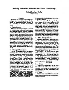
Once the system is approved as consistent, execution begins. Every control flow in JACAL starts with a communication originated by the user clicking on the source end of links not attached to a socket. Control flows are depicted as random color circles moving along links and transitions. The user can open new views of the system while it is running in order to observe inner behavior of more than one component at a time, while still having a global view of the system. Figure 7 shows the user interface of the JACAL application with a view of part of the case study described in [15], where a discussion of the implementation’s architecture can be found.
4 Detecting a Design Problem The example we chose for this paper presents a reentrant component (' % ). ' % can be in one of three possibles states:
8
&OLHQW
component accessing a passive storage
Figure 7: JACAL application window F
is a consistent state.
L
is an inconsistent state.
H
is an error state.
The & O L H Q W component accesses ' % through two links (of type Z U L W H ). Each time a signal is received from the user it issues a first Z U L W H (Z L ), leaving ' % in inconsistent state. It then performs some internal calculations (represented by a Q transition) and finally returns ' % to its initial state (F ) by sending a second Z U L W H (Z F ). Figure 8 shows the behavior level for the & O L H Q W component.
Figure 8: Behavior level for the
&OLHQW
component
This might model an invoice system storing documents in a sequential file. Z L would store an invoice header and Z F would write an invoice footer. State L is considered inconsistent, because ' % ’s integrity rules require that each header must be immediately followed by its corresponding footer. Error state H is reached when a Z L is received while ' % is in L state. This would correspond to a second header being written without a footer in between. Integrity cannot be restored neither by writing new headers nor by adding footers. This behavior is shown in Figure 9. Once the architecture is loaded into the JACAL environment (drawing it with the editor or opening a file), it can be put to run. Tokens are generated when the user clicks on the loose end of the link called J R . In Figure 10 the upper window of the environment contains the interface level (with a token passing through Z F ). In the lower window, component ' % is shown to be in state L (because the token has not reached ' % yet). Because of the multi-threaded implementation of the JACAL environment, concurrent execution of several control flows can easily be tested. This is how the design problem for this particular case study can be detected. If the user generates a second token in the J R link short before sending a first one, ' % will receive two consecutive Z L that will leave the component in error state (as shown in Figure 11). This corresponds to a pair of invoices being entered almost simultaneously in the system (possibly from two different workstations). 9
Figure 9: Behavior level for the
Figure 10: Interface level and
'%
'%
component
component
The architecture was originally intended to accept multiple simultaneous invoices, which is reflected in the choice of a reentrant component for & O L H Q W . This was probably a non-functional requirement by future system users. This error would prove very subtle to be discovered and corrected after implementation of the system. Testing techniques usually fail in detecting errors caused by synchronization problems like the one we are dealing with.
5 Solving a Design Problem To solve the problem described in Section 4 we proposed a change in the architecture. This change consisted in the addition of a third component (7 U D Q V ) acting as a transaction manager. The role of 7 U D Q V in the system will be to prevent a Z L (header writing) to be issued while ' % is in inconsistent state (the corresponding footer for the previous header has not yet been stored). This does not hinder concurrent generation of as many invoices as needed (this was considered a constraint on the architecture). 7 U D Q V just holds requests for Z L (headers) in a queue (named L W and represented by a link
10
Figure 11: Two tokens leave of type message) until
'%
'%
in error state
is restored to a consistent state.
The interface level for the proposed solution appears in Figure 12. Note that initialized by receiving a control flow when the system is started.
7UDQV
has a socket
LQLW
to be
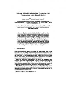
Figure 12: Solution (interface level) In the behavior level (Figure 13) component 7 U D Q V starts in a F state, corresponding to the consistent state of In this state, it can consume a waiting token from the L W queue, which will cause it to issue a Z L W (writing a header and hence leaving ' % in inconsistent state). It then waits until a token is placed in the F W queue (or consumes a token if one is already present) to restore ' % to state F . Note that during this time subsequent requests for Z L will be held in the L W queue until ' % is back in consistent state. '%.
After introducing this modification in the architecture it was tested again using the JACAL environment. Multiple tokens can be generated in J R one after another without ' % ever reaching state H . Tokens get accumulated in queues L W and F W (the environment shows a counter near each P H V V D J H link name to indicate how many tokens are waiting in the queue) and are synchronically released by the logic in 7 U D Q V .
11
Figure 13: Solution (behavior level of component
7UDQV)
The proposed change is incremental. This means that every component, link and socket in the original architecture was left untouched. Links L and F have now sockets in component 7 U D Q V as their source instead of sockets Z L and Z F in component & O L H Q W (compare Figure 10 and Figure 12). Links of type P H V V D J H where attached to this sockets instead of links of type Z U L W H . No change at all was required at the behavior level. Both states and transitions are intact. If the architecture represented an already implemented system, this might mean that the code for the components would not need to be modified (this depends on the implementation chosen). The main reason why the solution was so smooth is the low coupling provided by ADL likes JACAL as opposed to programming languages. Labels in the behavior level of components refer to sockets in the interface level without making assumptions about links connected to them or components connected to those links. Another benefit of JACAL (compared to other ADLs) essential for the development of incremental solutions lies in the lack of constraints on the type of links that can be attached to a particular socket.
6 Conclusions Executing software architectures is a powerful method to test a system’s design in early stages of its development. The main advantage consists in the detection of errors without the need to previously state the properties one pretends to test. In this paper we explained how the JACAL language and its software environment can be used to detect errors in this way. The definition of a new ADL was proven a good choice, as the expressive power of JACAL to describe an architecture’s behavior and the ability to actually show the execution of the system on top of its graphical representation is unmatched by existing ADLs. This features combined with formal semantics made possible the development of a software tool that is easy to operate whithout requiring from the user any training beyond knowledge of the language itself.
7 Further Work Although JACAL revealed as a very versatile multi-purpose ADL, we do not intend every designer to adopt it in case they want to observe the execution of their architectures. A fair alternative would be to define translations from other ADLs into JACAL so that architectures described in those languages can be tested using the JACAL environment. An important step towards this goal consists in adding to the environment a feature to import a text file containing the definition of an architecture in a textual representation of JACAL (like the one defined for extended event traces in [6]). Translators could then be defined from textual representations of foreign ADLs into JACAL using standard compiler build techniques. Currently error detection with the environment relies on personal observation of the execution. This process demands permanent attention from the designer during simulations. Adding a log generation option to the environment would produce an output that could be manually or automatically examined once execution is finished. Proposed extensions to the JACAL language, like fault-tolerance information or system metrics can be
12
mapped to extensions to the environment, thus improving its functionality.
References [1] Abowd, G., Allen, R. and Garlan D. “Using style to give meaning to software architecture,” in Proceedings of SIGSOFT’93: Foundations of Software Engineering, Software Engineering Notes, 118(3):9-20. ACM Press, December 1993. [2] Allen, R. and Garlan, D. “Beyond definition/use: Architectural interconnection,” in Proceedings of the ACM Interface Definition Language Workshop, 29(8). SIGPLAN Notices, August 1994. [3] Allen, R. and Garlan, D. “Formalizing architectural connection,” in Proceedings of the 16th International Conference on Software Engineering, pp. 71-80. Sorrento (Italy), May 1994. [4] Bandinelli, S. “Fresh approaches to software architecture description: overview and assessment,” internal report. [5] Bandinelli, S., Braga, M., Fuggetta, A., Lavazza, L. “The architecture of the SPADE-1 process centered SEE,” in 3rd European Workshop on Software Process Technology. Grenoble (France), February 1994. [6] Broy, M., Hofmann, C., Krüger, I., Schmidt, M. “A Graphical Description Technique for Communication in Software Architectures.” Technical Report, TUM-I9705. Technische Univerität München, February 1997. (http://www4.informatik.tu-muenchen.de/reports/TUM-I9705.html) [7] Fischer, G., Girgensohn, A., Nakakoji, K., Redmiles, D. “Supporting software desingners with integrated domain-oriented design environments,” in IEEE Transactions on Software Engineering, June 1992. [8] Garlan, D., Allen, R. and Ockerbloom, J. “Exploiting style in architectural design environments, ” in Proceedings of SIGSOFT’94: Foundations of Software Engineering, Software Engineering Notes, 118(3):920. ACM Press, December 1994. [9] Garlan, D. and Shaw, M. “An introduction to software architecture,” in V. Ambriola and G. Tortora, editors, Advances in Software Engineering and Knowledge Engineering, volume I. World Scientific Publishing Company, 1933. [10] Garland, D., Monroe, M. and Wile, D. “ACME: an architectural interconnection language.” Technical Report, CMU-CS-95-219. Carnegie Mellon University, November 1995. [11] Ghezzi, C., Mandrioli, D., Morasca, S., Pezzè, M. “A general way to put time in Petri Nets,” in 5th International Workshop on Software Specification and Design. IEEE, May 1981. [12] Ghezzi, C., Mandrioli, D., Morasca, S., Pezzè, M. “A unified high-level Petri net model for time-critical systems,” in IEEE Transactions on Software Engineering. 17(2),160-172, 1991. [13] Ghezzi, C., Jazayeri, Mandreoli, D. “Fundamentals of Software Engineering.” Prentice-Hall, 1991. [14] Inverardi, P. and Wolf, A. “Formal specification and analysis of software architectures using the chemical abstract machine model,” in IEEE Transactions on Software Engineering, 21(4), April 1995. [15] Kicillof, N. “Running Software Architectures.” Unpublished grade thesis. Universidad de Buenos Aires, November 1997. [16] Krishnamurthy, B., Rosenblum, D. “Yeast: a general purpose event-action system,” in IEEE Transactions on Software Engineering, 20(9), September 1995. [17] Luckham, D., Augustin, L., Kennedy, J., Vera, J., Bryan, D. and Mann, W. “Specification and analysis of system architecture using Rapide,” in IEEE Transactions on Software Engineering, 21(4), April 1995. [18] Luckham, D. and Vera, J. “An event-based architecture definition language,” in IEEE Transactions on Software Engineering, September 1995. [19] Luckham, D., Vera, J. and Meldal, S. “Three concepts of system architecture,” Program Analysis and Verification Group Report No. 70, Technical Report No. CSL-TR-95-674. Stanford University, 1995. (http://elib.stanford.edu/Dienst/ UI/2.0/Describe/ stanford.cs%2fCSL-TR-95-674) 13
[20] Medvidovic, N. “A classification and comparison framework for software architecture description languages, ” Technical Report, UCI-ICS-97-02, University of California, Irvine, January 1997. [21] Perry, D. and Wolf, A., “Foundations for the study of software architecture,” in ACM SIGSOFT Software Engineering Notes, 17(4), October 1992. [22] Pinna, G. “Petri nets and their compositional problems,” Ph.D. Thesis: TD - 2/90, Dipartamento di Informatica, Univesità di Pisa, March 1990. [23] Reisig, W. “Petri nets –an introduction,” EATCS Monographs on Theoretical Computer Science, volume 4. Springler-Verlag, 1985. [24] Shaw, M. and Garlan, D. “Characteristics of higher-level languages for software architecture,” Technical Report, CMU-CS-94-210. Carnegie Mellon University, December 1994. [25] Shaw, M. et al. “Abstractions for software architecture and tools to support them,” in IEEE Transactions on Software Engineering, 21(4), April 1995. [26] Taylor, R. et al. “A component- and message-based architectural style for GUI software,” IEEE Transactions on Software Engineering, June 1996. [27] Yankelevich, D. “Local nets,” in Proceedings of the XVIII Conferencia Latinoamericana de Informática, PANEL 92, 1992.
14