DEVELOPMENT OF A SHORT DURATION HYPERSONIC TEST FACILITY AT UNIVERSITI TENAGA NASIONAL (Date received: 31.10.2007)
Amir Al-Falahi1, Mohd. Zamri bin Yusoff2 and Talal Yusaf3 Universiti Industri Selangor (UNISEL), Jalan Timur Tambahan, 45600 UNISEL, Batang Berjuntai, Selangor 2 Universiti Tenaga Nasional, College of Engineering, (UNITEN), Jalan Kajang-Puchong, 43009 UNITEN, Kajang, Selangor 3 University of Southern Queensland, Faculty of Engineering and Surveying (USQ), Toowoomba 4350, Australia Email:
[email protected] 1
abstract This paper describes the development of a short duration hypersonic test facility at the College of Engineering, Universiti Tenaga Nasional (UNITEN). The facility is the first of its kind in Malaysia. The facility will allow various researches to be done in the field of high speed supersonic and hypersonic flows. It is designed so that it can be used as a free piston tunnel, shock tube and shock tunnel. The maximum mach number obtainable depends on the type of the driver and driven gases. It is shown that a mach number of 4 can be achieved if CO2 is used as the driven gas and Helium is used as the driver gas with diaphragm pressure ratio of 74.76. Experimental measurements were performed with the facility working as shock tube. The barrel temperature was measured using in-house developed fast response surface junction E-type thermocouple while the pressure was measured using fast response quartz pressure transducer. The pressure and temperature results clearly show the formation of shock wave and its reflection causing the pressure and temperature to increase rapidly. Keywords: Hypersonic Test Facility, Shock Tunnel, Shock Tube, Free-Piston Tunnel, Shock Wave
1. INTRODUCTION
There are many different ways to generate a source of air at a sufficiently high temperature and pressure to act as the working fluid of a hypersonic wind tunnel. This includes hotshot tunnels, plasma jets, shock tubes, shock tunnels, free-piston tunnels, and light gas guns [8]. Various hypersonic wind tunnels have been constructed at different universities and research centers all over the world such as at University of Oxford [4], University of Southampton in the United Kingdom [5], University of Queensland [7] and University of Southern Queensland in Australia [3]. However, these facilities are very costly and very expensive to run and maintain. A low cost facility, which could show the various effects of hypersonic ionisation and dissociation, along with experimental testing of hypersonic heat transfer effects has been developed in Universiti Tenaga Nasional (UNITEN). The facility is the first of its kind in Malaysia. The hypersonic test facility has been designed so that it can be easily used as a shock-tube, shock tunnel and free piston tunnel interchangeably. Shock tube uses a high-pressure gas to set up a shock wave which will compress a low-pressure gas and heat it to very high temperatures. It consists of two tubes separated by a diaphragm [9]. One of the tubes is filled with a driver gas at a high pressure and the other tube is filled with a driven gas at a low pressure. The diaphragm between the two tubes is ruptured and the highpressure driver gas rushes into the driven section, setting up a shock wave which compresses and heats the driven gas. Shock tunnels are wind tunnels that operate at high Mach number for time intervals up to a few milliseconds by using air heated and compressed in a shock tube. The shock tunnel consists of a shock Journal - The Institution of Engineers, Malaysia (Vol. 69, No.1, March 2008)
tube, a secondary diaphragm, a nozzle attached to the end of the driven section of the shock tube, a model test section and a damp tank [9]. The incident shock wave caused by the rupture of the primary diaphragm compresses and heats the test gas before reflecting from the nearly closed end of the tube at the nozzle throat. The shock wave travels back up the shock tube through the processed gas causing it to be further heated and compressed to the point where the rupture pressure of the secondary diaphragm is reached. The thin secondary diaphragm ruptures and the processed test gas expand through the nozzle into the test section. The free-piston tunnel is quite similar to the shock tunnel apart from a light piston located after the primary diaphragm in the driven section [2]. When the diaphragm ruptures, the piston is propelled through the driven tube, compressing the gas ahead of it. This causes a shock to be reflected from the end of the driven tube to the piston, causing further gas heating. The piston comes to rest with equal pressure on its two sides and the heated and compressed driven gas ruptures a secondary diaphragm and flows through the nozzle. The objective of building such facility is to generate gas flows or gas conditions of sufficiently high temperature and pressure that are difficult to achieve in other test devices. The facility is to be used to test a new fiber-optic pressure sensor for high speed flows in gas and steam turbines, which is being developed, and to study the heat transfer phenomena associated with high speed flows. Apart from that, the facility can be used for other high speed flow studies such as: 1. Testing of supersonic and hypersonic bodies such as aircraft and space re-entry vehicles, 19
amir al–falahi, et al.
2. Development of high power gas dynamic and chemical lasers, 3. Fluid dynamics and thermodynamics of high-speed compressible flow, 4. Fluid dynamics and thermodynamics of unsteady wave motion, 5. Shock waves 6. Boundary layers in high speed flow 7. Testing of instrumentations for high speed flows applications 8. High quality data for Computational Fluid Dynamics (CFD) codes validation This project is a collaboration project between UNITEN and the University of Southern Queensland, Australia to design and construct a 7 m short duration hypersonic test facility and supported by the Ministry of Science, Technology and Innovation, Malaysia under an IRPA Grant No. 03-99-03-10002-EAR.
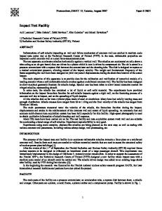
Figure 1(a): Schematic Diagram of the Hypersonic Test Facility at UNITEN
6. Piston compression section: A piston is placed in the barrel (driven tube) adjacent to the primary diaphragm so that when the diaphragm ruptures, the piston is propelled through the driven tube, compressing the gas ahead of it. This piston is used with free-piston tunnel tests only. 7. Discharge valve: to discharge the driven section after each run. 8. Vacuum gauge: to set the pressure inside the barrel section to a pressure less than atmospheric pressure (vacuum pressure). 9. Barrel section: a shock tube section (smooth bore), to be filled with the required test gas (air, nitrogen or carbon dioxide). 10. Barrel extension: the last half meter of the barrel on which the pressure transducers and thermocouples are to be mounted. 11. The secondary diaphragm: a light plastic diaphragm to separate the low pressure test gas inside the barrel from the test section and damp tank which are initially at vacuum prior to the run. 12. Test section: this section will expand the high temperature test gas through a nozzle to the correct high enthalpy conditions needed to simulate hypersonic flow. A range of Mach numbers is available by changing the diameter of the throat insert. 13. Vacuum vessel (damp tank): to be evacuated to about 0.1 mm Hg pressure before running. Prior to a run, the barrel, test section and damp tank are to be evacuated to a low-pressure value. The facility consists of two major sections, the driver section and the driven section. These two sections are filled with gasses at 2 different pressures and are initially separated by a thin diaphragm. The diaphragm is designed to withstand a certain pressure ratio. When this ratio is exceeded, the high-pressure gas ruptures the diaphragm and expands into the low-pressure gas.
3. DESIGN CALCULATIONS
Figure 1(b): Photograph of the hypersonic test facility at UNITEN
2. DESCRIPTIONS OF THE FACILITY
Figures (1a) and (1b) show the schematic diagram and a photograph of the high speed test facility respectively. The facility consists of the following components as listed in Figure 1(a): 1. Driver section: a high-pressure section (driver), which will contain the high pressure driver gas. 2. Discharge valve: to discharge the driver section after each run. 3. Pressure gauge: to read the pressure inside the driver section, this section is also provided with a static pressure transducer to record the exact value of the driver pressure P4 at which the diaphragm ruptures. 4. Vacuum pump: when the driver gas is not air (e.g. Helium or Hydrogen) then the driver section should be evacuated and refilled with the required driver gas. 5. The primary diaphragm: this is a thin aluminum membrane to isolate the low-pressure test gas from the high-pressure driver gas until the compression process is initiated. 20
A simple shock tube assembly and its x-t diagram are illustrated in Figures 2(a) and 2(b) respectively. When the diaphragm is ruptured, a shock wave travels into the driven section while a rarefaction wave travels back into the compression chamber. The pressure and temperature distributions along the tube, at an instant t1, are displayed in Figures 2(c) and 2(d) respectively. Let us denotes pressures by P, densities by ρ, sound speed by a and flow velocities by u. The dotted line in Figure 2(b), which separates region of gas at pressures P3 and P2, denotes the position occupied by that gas which was originally at the diaphragm. The gas to the right has been compressed and heated by the shock wave; the gas to the left of this line has been expanded and cooled by the rarefaction wave. Therefore there will be a change of gas type, temperature and density, while velocities and pressures are the same on both sides. Such point is known as contact discontinuity or surface. Referring to Figure 2(a), the region ahead of the shock is indicated with “1”, the region comprised between the shock and the contact surface is denoted with “2”, ahead of the rarefaction wave travelling into the driver section is region “4”, and between the tail of the rarefaction wave and the contact surface is region “3”. When the shock wave reaches the end of the shock tube, it undergoes a reflection. By considering the shock wave equation [1], the Mach number of the incident shock wave, MS can be written as a function of P1 and P2 which are pressures ahead and behind shockwave and the specific heat ratio, γ as follows : γ + 1 P2 – 1 + 1 Ms = P 2γ 1
(1)
Journal - The Institution of Engineers, Malaysia (Vol. 69, No.1, March 2008)
development of a short duration hypersonic test facility at uniten
1. Given the initial conditions P4, T4, γ4; P1, T1, γ1 ; 2. The diaphragm pressure ratio P4/P1 can be determined from Equation (3). This defines the required diaphragm pressure ratio to generate the given Mach number. 3. The pressure ratio across the shock wave can be obtained by rearranging Equation (1) and gives the incident shock strength: 2γ1 P2 2 (Ms – 1) = 1 + (5) γ1 + 1 P1 4. Other incident shock properties can be calculated from the following equations : γ+1 P + 2 γ–1 P1 T2 P2 = γ + 1 P 2 T1 P1 1 + γ – 1 P1
(6)
5. The flow velocity u2 behind the shock can be determined via the shock relation : 1 2γ 2 γ + 1 a1 P2 (7) – 1 u2 = γ γ–1 P2 P1 + γ+1 P1
Figure 2: Wave diagrams in a shock tube
Similarly, the equation for wave speed of the shock, W, can be written as : P2 W = a1 γ + 1 – 1 + 1 P1 2γ
(2)
6. P3/P4 = (P3/P1)/(P4/P1) = (P2/P1)/(P4/P1) defines the strength of the incident expansion wave. 7. The flow velocity u3, behind the rarefaction wave, is given by : (γ4 – 1)
where a1 is the speed of sound in the undisturbed gas in the driven tube. The shock tube equation can be derived as follows : P (γ4 – 1)(a1/a4)(P2/P1 – 1) P 4 = 2 1 – P1 P1 2γ1 [2γ1 + (γ1 + 1) (P2/P1 – 1)]
– 2 γ4/(γ4 – 1)
(3)
1+
(8)
4
8. All other thermodynamic properties immediately behind the expansion wave can be found from the isentropic relations, γ
γ
ρ3 T3 (γ – 1) P3 = = ρ4 T4 P4
Solving for Ms, and replacing P1/P2 in Equation (3) we have:
u3 P3 2γ 2 – 1 = a4 P4 γ4 - 1
2γ1 2 (Ms – 1) γ1 + 1
(9)
9. The local properties inside the expansion wave are given by :
P4 = 2 P1 γ – 1 a1 Ms – 1 γ 2γ– 1 1 – 4 γ4 + 1 a4 Ms 4
(4)
4
Equation (3) gives the incident shock strength P2/P1 as an implicit function of the diaphragm pressure ratio P4/P1. An evaluation of this relation shows that, for a given diaphragm pressure ratio P4/P1, the incident shock strength P2/P1 will be stronger as the speed of sound ratio a1/a4 is smaller. The speed of sound in a light gas is faster than in a heavy gas [1]. Thus, to maximise the incident shock strength for a given P4/P1, the driver gas should be a low-molecular-weight gas at high temperature and the driven gas should be a high-molecular-weight gas at low temperature. Therefore, many shock tunnels use H2 or He for the driver gas and heat the driver gas by electrical means, chemical combustion or by free-piston compression. The analysis of the flow of a calorically perfect gas in a shock tube is now straightforward. For a given desired shock Mach number Ms : Journal - The Institution of Engineers, Malaysia (Vol. 69, No.1, March 2008)
u ρ γ-1 γ-1 a = 1 – , = 1 – a 2 2 a4 ρ4 4 2 x u = a4 + γ+1 t
u a4
2 (γ – 1)
, (10)
Since there must be no discontinuity of pressure or flow speed across the contact surface, we have P2 = P3 and u2 = u3, these equations now give : γ -1 P2 1 – 1 – 1 a γ + 1 P1 = 1 a4 γ–1 P2 γ -1 1 + 1 + (11) γ1 + 1 γ+1 P1 2 = γ4 – 1
1 –
P1 P2 P4 P1
(γ4 – 1) 2γ4
21
amir al–falahi, et al.
Equation (11) relates the shock strength P2/P1 to the diaphragm pressure ratio P4/P1 in the compression and expansion chambers, as shown in Figure 3. It is noteworthy that, for any practical purposes, the pressure ratio P2/P1 is never much higher than 10 when the same gas is used in the driver and driven section.
The effect of different gas combination can be examined by considering a large initial compression ratio: P4 >> 1 ⇔ P1
P1 P2 P4 P1
(γ4 – 1) 2γ4
⇒0
Equation (11) will reduces to:
a = a4
1 –
γ1 - 1 γ1 + 1
γ -1 1 + 1 γ1 + 1
P2 – 1 P1
γ–1 P2 + γ+1 P1
=
2 γ4 – 1
(13)
Here, P2/P1 is the maximum theoretical achievable shock strength. This equation can be further simplified if P2/P1 is large : P2 P1 (max)
Figure 3: Shock strength as function of initial pressure ratio, using air in both sections
2
2γ1(γ1 + 1) a4 = (γ4 - 1)2 a1
(14)
Therefore, it can be concluded that to obtain strong shocks in the shock tube, the sound speed ratio a4/a1 should be as high as possible and the gas (γ4 – 1) should be as small as possible. Similar conclusion can be made from Figure 5, which shows the dependence of the shock Mach number on the pressure ratio P4 /P1 for different driver/driven gas combinations.
By solving Equation (11), P2 can be determined and subsequently all other flow properties in the shock tube. The Mach number of the reflected shock wave, MR , is given by :
MR = MS
γ +1 γ1 + 1 P2 P 1 – 1 + 1 + 2 2 γ1 - 1 γ1 - 1 P1 P1 γ + 1 P2 P2 P2 γ1 + 1 1 + 1 + γ1 - 1 P1 P1 P1 γ1 - 1
1 2
(12)
The dependence of MS and MR as function of the pressure ratio P4/P1 [from Equations (4) and (12)] is shown in Figure 4.
Figure 5: Variation of incident MS and reflected MR shock Mach number for various driver/driven gas combinations as function of diaphragm pressure ratio (P4/P1). [6]
Figure 4: Variation of incident and reflected shock Mach numbers, for a shock tube with air as driver and driven gas and T4/T1=1, over a small range of P4/P1. [10]. 22
It can been seen from Figure 5, at a given temperature and pressure ratios, the shock Mach number can be increased by choosing increasingly lighter driver gases. Also, for a given driver/ driven gas combination, the shock Mach number can be increased by increasing the initial temperature ratio (T4/T1) which determines the initial sound speed ratio. Calculations have been performed for different driver and driven gas combinations. The solutions for different gas combinations are shown in Figures 6 (a), 6(b) and 6(c) for air, CO2 and N2 as driven gasses respectively. The corresponding diaphragm pressure ratios to get a target Mach number of 4 for different combination of gasses are shown in Table 1. The results shows that the required diaphragm pressure ratios in order to get target Mach number of 4 are 65.4, 46.9 and 65.91 Journal - The Institution of Engineers, Malaysia (Vol. 69, No.1, March 2008)
development of a short duration hypersonic test facility at uniten
Table 1: Calculated diaphragm pressure ratios to get Mach number of 4 for different gas combinations
Driven Gas
Driver Gas
(P4/P1)
Air
Air Helium Hydrogen
17740 126.46 65.4
CO2
Air Helium Hydrogen
1909 74.76 46.87
N2
Air Helium Hydrogen
18965.6 128.19 65.91
Table 2: Calculated diaphragm pressure ratios to get Mach number of 4 with He as driven gas
Diaphragm Pressure Ratio (P4/P1) Ms 4.0
He-Air 126.46
for H2-Air, H2-CO2 and H2-N2 combinations respectively. However, since H2 is easily flammable at high temperature at the end of the barrel, these options should be avoided. Consequently He is preferable and three choices are available as shown in Table (2). The outcome from this table is that He-CO2 is the most suitable gas combination to get high Mach number value safely.
He-CO2 74.76
He-N2 128.91
Figure 7: Pressure transducer location
4. EXPERIMENTAL MEASUREMENT
Experimental measurements were performed with the facility working as shock tube with the end of the driven section closed and free-piston tunnel, in which a light plastic piston is placed in the barrel adjacent to the primary diaphragm so that when the diaphragm ruptures, the piston is propelled through the driven tube, compressing the gas ahead of it. The barrel temperature was measured using in-house developed fast response surface junction E-type thermocouple. The thermocouple junctions were constructed by using 120 abrasive grit. The pressure was measured by a commercial quartz pressure transducer (PCB mode number 112B11) and an inline charge amplifier (PCB model number 402A03). The pressure transducer and the thermocouple were installed at the wall of the tube at about 75 mm from the closed end as shown in Figure 7. The boundary conditions of the run were as stated below.
Figure 6: Variation of shock Mach number with P4 /P1 Journal - The Institution of Engineers, Malaysia (Vol. 69, No.1, March 2008)
Driver gas: Air γ4 = 1.4 ; Driven gas: Air ; γ1 = 1.4 Driver pressure P4 = 12 bar; Driven pressure P1 = 1bar ; T1 = T4 = 300 K 23
amir al–falahi, et al.
Figure 8: Pressure history inside the barrel (shock tube)
Figure 9 : Surface temperature profile inside the barrel (shock tube)
Figure 10 : Heat flux profile inside the barrel (shock tube)
Figure 11: Pressure history inside the barrel (free-piston tunnel)
Figure 12: Surface temperature profile inside the barrel (free-piston tunnel)
Figure 13 : Heat flux profile inside the barrel (free piston tunnel)
The pressure and temperature histories for the first run are displayed in Figures 8 and 9 respectively. It clearly shows the effects of shock wave propagations through the barrel. As the shock wave travels from the burst diaphragm, it increases the temperature and pressure of the driven gas. The shockwave reflected off the closed end of the barrel and passes back through the driven air, further processing the gas and causing further increase of the pressure and temperature. The shock Mach number obtained is
approximately 1.7 which agree very well with value predicted by the theory at pressure ratio of 12. Similarly, the expansion wave reflects at the end of the driver section. The reflected shock then interacts with either the contact surface or the reflected expansion wave. The transient heat flux through the wall of the tunnel can be determined by using numerical convolution technique and the results are shown in Figure 10. The results show that the heat flux increase instantaneously when a shockwave passes.
24
Journal - The Institution of Engineers, Malaysia (Vol. 69, No.1, March 2008)
development of a short duration hypersonic test facility at uniten
In the second run, the facility has been modified to become a freepiston tunnel. In this arrangement, when the diaphragm ruptures, the piston is propelled through the driven tube, compressing the gas ahead of it causing a pressure and temperature rise at the end of the barrel. The measured pressure, temperature and heat flux for this run are given in Figures 11, 12, and 13 respectively. From these figures, the pressure and temperature profiles have been significantly increased due to the presence of the light plastic piston.
[3] East, R.A. (1960), ‘The performance and operation of the University of Southampton hypersonic gun tunnel’, Univ. of Southampton Aero. and Astro. Rep. No. 135, 1960
5. CONCLUSIONS
[5]
A short duration hypersonic test facility has been developed in UNITEN. The facility is the first of its kind in Malaysia. The design calculations showed a direct proportional relationship between Mach number and diaphragm pressure ratio and inverse proportional relationship with speed of sound ratio. Therefore by selecting a suitable combination of gasses a required mach number can be obtained at a safe diaphragm pressure ratio. It is found that mach number of 4 can be obtained if a combination of He-CO2 is used with diaphragm pressure ratio of 74.76. Experimental measurements with the air-air combination and facility working as shock tube clearly shows the effect of shockwave propagation inside the barrel and increases the temperature and pressure of the driven gas. The reflection of the shockwave further increases the pressure and temperature of the driven gas. The measured Mach number obtained agree very well the analytical calculations used in designing the facility and hence validate the design. n
nomenclature P T M a u W t γ ρ
Pressure Temperature Mach number speed of sound flow velocity shock wave speed time specific heat ratio density of working fluid
subscript 1 2 3 4 s R
Initial state in driven section Flow conditions between shock wave and contact surface Flow conditions between rarefaction wave and contact surface Initial state in driver section incident shock wave reflected shock wave
references [1] Pope, A. and Goin, K.L. (1965), ‘High-Speed Wind Tunnel Testing’, John Wiley, New York, 1965 [2] Buttsworth, D.R, Jacobs, P.A, and Jones, T.V (2002), ‘Simulation of Oxford University Gun Tunnel performance using a quasi-0ne-dimensional model’, Shock Waves, 11: 377–383, 2002 Journal - The Institution of Engineers, Malaysia (Vol. 69, No.1, March 2008)
[4] Jacobs, P.A. (1994), ‘Quasi-One-Dimensional Modeling of a Free-Piston Shock Tunnel’, AIAA Journal, Vol.32, No. 1, January, 1994 Buttsworth, D.R (2002), ‘Heat transfer during transient compression: measurements and simulation’, Shock Waves, 12 : 87-91, 2002
[6] Wintenberger, E. (2002), ‘6 Inch Shock Tube experiments’, 315 Guggenheim, January 5, 2002 [7]
Bray, K.N.C (1961), ‘Evaluation of The Hypersonic Gun Tunnel’, Proceedings of the ARS International Hypersonic Conference, August, 1961
[8] Anderson, J.D (1990), ‘Modern Compressible Flow with Historical Perspective’, McGraw Hill, New York, 1990 [9] Wright, J.K. (1961), ‘Shock Tubes’, John Wiley and Sons, 1961. [10] Holder, D.W. and Schultz, D.L, (1960), On the flow in a reflected shock tunnel, Aeronautical Research Council (ARC) Reports and Memoranda, No. 3265, 1960.
PROFILEs amir al-falahi Mr. Amir Al-Falahi is currently a Senior Lecturer in Universiti Tenaga Nasional (UNITEN), Malaysia. His research interest is high speed flow experimentation technique.
Engr. prof. dr mohd. zamri bin yusoff Engr. Prof. Dr Mohd. Zamri bin Yusoff is currently the Dean of the College of Engineering, UNITEN. He obtained his PhD in Mechanical Engineering from the University of Birmingham, UK in 1997. His research interests are in CFD, numerical modeling, gas dynamics, condensation and other energy related studies.
dr talal yusaf Dr Talal Yusaf is currently a Senior Lecturer in the University of Southern Queensland, Australia. He obtained his PhD in Mechanical Engineering from Universiti Kebangsaan Malaysia (UKM), Malaysia. His areas of specialisations are fluid mechanics, biotechnology and combustion.
25