Proceedings of LINAC 2006, Knoxville, Tennessee USA. TUP034. Technology, Components, and Subsystems. Cryogenics and Superconductivity. 321 ...
Proceedings of LINAC 2006, Knoxville, Tennessee USA
TUP034
DEVELOPMENT OF A SUPERCONDUCTING RF MODULE FOR ACCELERATION OF PROTONS AND DEUTERONS AT VERY LOW ENERGY M. Pekeler, K. Dunkel, C. Piel, P. vom Stein ACCEL Instruments GmbH, Friedrich-Ebert-Str. 1, 51429 Bergisch Gladbach, Germany Abstract A prototype superconducting accelerator module housing six 176 MHz half wave resonators and three superconducting solenoids is currently under production at ACCEL as part of a 40 MeV linear accelerator at the SOREQ NRC [1]. The module will accelerate protons and deuterons from energy of 1.5 MeV/u up to 6.5 MeV. The design is based on a peak electric field of 25 MV/m and maximum 10 W of power dissipated into the helium bath by each cavity. Main design considerations of the cavities, solenoids, tuners and couplers as well as for the module especially in view of assembly and alignment will be presented. Cold test results of the cavities obtained in ACCEL’s new cold RF test facility will be presented. All components like tuners, helium vessel, solenoids and couplers as well as thermal shield, magnetic shield and vacuum vessel have been produced in the meantime and the assembly of the module is almost finished. The module will be RF tested at 4.2 K at ACCEL before shipment to Israel in order to demonstrate cavity performance after assembly.
MODULE DESIGN CONSIDERATIONS The prototype superconducting module has to accelerate protons and deuterons at very low energy. Beam dynamic calculations show, that the space between adjacent cavities must be then minimized in order to preserve the good beam quality from the gun and RFQ and achieve a good emittance at the exit of the module. Therefore it was decided to integrate superconducting solenoids into the SRF module as it is also done at other institutes like Argone and Triumf for modules housing quarter wave cavities. Backing coils ensure that the stray field of the solenoids are well below the critical magnetic field of niobium at the location of the halfwave resonators to avoid performance degradation of the cavities. Also from beam dynamic calculations the required alignment tolerance of cavities and solenoids was determined to be 0.3 mm in transverse direction. In order to achieve this alignment also after cooldown, it was decided to use a stainless steel reference frame produced out of 316LN with intermediate annealing during the manufacturing process to remove stresses thus avoiding deformation during cooldown. All cavities and solenoids are aligned in respect to this reference frame which can be machined very precisely with todays large CNC milling machines.
Technology, Components, and Subsystems Cryogenics and Superconductivity
Table 1: Main Design Parameters for the Prototype Superconducting Module Dimensions and weight
Height 3 m Width: 1.2 m length: 2.6 m weight: 6 tons
Thermal mass
80 MJ @ 4 K 20 MJ @ 70 K
Volume of liquid helium
200 l
Crogenic losses
10 W static @ 4 K 70 W total @ 4 K 120 W @ 70 K
Operating pressure (temperature)
1.2 bar (4.4 K)
Beam pipe diameter
30 mm
Solenoid field
4.7 x 10⁸
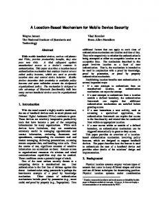
In order to test 176 MHz half wave resonators, a cold RF test facility was built up at ACCEL. The facility is big enough to allow for testing of cavities in vertical cryostat, but also testing complete assembled modules. The preparation of the halfwave cavities was done using our closed loop chemical polishing facility. In total about 150 µm were removed from the inner surface (BCP 1:1:2) followed by high pressure rinsing and assembly of test antennas in the clean room.
Figure 2: Test results of a the halfwave resonators produced for the SARAF linac. A prototype half wave resonator was built and tested at the beginning of the project and it was seen, that strong multipacting barriers predicted by simulations, present at very low fields might limit the routine cavity operation [2][3]. After slightly redesigning the cavity geometry this multipacting barriers were strongly reduced and the six
Technology, Components, and Subsystems Cryogenics and Superconductivity
Proceedings of LINAC 2006, Knoxville, Tennessee USA series cavities were tested consecutively with all cavities exceeding the specification. Figure 2 shows the vertical test results compared to the design parameters and the result of the prototype cavity. It is worth mentioning, that two of the cavity results shown in Figure 2 were measured in a stage, where the helium vessel was already welded to the cavity.
TUP034
Figure 3 shows the module at an intermediate assembly step.
SOLENOID TEST RESULTS All three solenoids were tested in a bath cryostat and reached design current of 132 A (corresponding to 6 T solenoid field) field after up to three training quenches. The stray field on axis at the location of the cavity was measured to be below 100 mT. The maximum current the solenoids were excited to during the test was 150 A. At this field the solenoid was not limited by quench.
MODULE ASSEMBLY After successful qualification of the cavities and solenoids the assembly of the prototype superconducting module could be started. The module assembly can be divided in several steps: •
• • • • • • • • • • • •
Assembly of cavity string inside the clean room, where all cavities and solenoids with intermediate bellow sections, cold part of input coupler and pick-up probe are assembled and attached to the reference frame. Leak check of cavity vacuum Attachment of helium distribution system to the helium vessel of cavities and solenoids Assembly of string to the top plate of the vacuum vessel Alignment measurement of cavities and solenoids Instrumentation and cabling Introduction of magnetic shield and thermal shield into vacuum vessel Superinsulation of cold mass Coupler assembly Introduction of cold mass into vacuum vessel Assembly of thermal transitions inside clean room Leak checks Cool down to 4 K, leak check RF test of cavities and function test of solenoids
The assembly of the module is scheduled to be finished at the End of August. The RF test of the module is schedule for September and the installation into the SARAF linac at the SOREQ institute in Israel can follow immediately after successful RF test.
Technology, Components, and Subsystems Cryogenics and Superconductivity
Figure 3: Intermediate assembly step of the prototype superconducting module. The completed string of six cavities and three solenoids is attached to the top plate
CONCLUSION A prototype superconducting module housing six halfwave resonators optimized for acceleration of beta=0.09 particles was designed and produced at ACCEL. After successful test of key components like cavities and couplers, the module is currently under final assembly. The assembled module will be fully tested with RF at ACCEL’s cold RF test facility and the delivery and installation of the module to the SOREQ accelerator can start immediately after successful RF test and demonstration of module parameters.
REFERENCES [1] A. Nagler et al, Status of the SARAF Project, this conference. [2] C. Piel et al, First stage of a 40 MeV proton deuteron accelerator commissioning, Proceedings of the 10th European Particle Accelerator Conference, EPAC 2006, Edingburgh, UK. [3] H. Vogel et al, Multipacting in a 176 MHz beta = 0.09 half wave resonator, ICFA workshop on Highpower Superconducting Ion, Proton, and MultiSpecies Linac, HPSL 05, Naperville, IL.
323