Abstract. The Stern-Gerlach-Zentrum SGZ recently founded at the University of Frankfurt allows to setup larger intense experiments now in accelerator physics, ...
Proceedings of LINAC 2006, Knoxville, Tennessee USA
MOP051
DEVELOPMENT OF AN INTENSE NEUTRON SOURCE “FRANZ” IN FRANKFURT O. Meusel, L.P. Chau, I. Mueller, U. Ratzinger, A. Schempp, K. Volk, C. Zhang IAP, University Frankfurt/Main, Germany S. Minaev, ITEP, Moscow, Russia
Abstract The Stern-Gerlach-Zentrum SGZ recently founded at the University of Frankfurt allows to setup larger intense experiments now in accelerator physics, astrophysics and material science research. It is planned to develop an intense neutron generator within the next 4 years. The proton driver linac consists of a high voltage terminal already under construction to provide primary proton beam energies of up to 150 keV. A volume type ion source will deliver a DC beam current of 100-250 mA at a proton fraction of 90%. A low energy beam transport using two solenoids will inject the proton beam into an RFQ while a chopper at the entrance of the RFQ will create a pulse length in the range of 100 ns at a repetition rate of up to 250 kHz. A drift tube cavity for the variation of the beam energy in a range from 1.9 to 2.4 MeV will be installed downstream of the RFQ. Finally a bunch compressor of the Mobley type forms a proton pulse length of 1 ns at the Li target. The maximum energies of the neutrons will be adjustable between 100 keV and 500 keV by the primary proton beam energy. The detailed concept of the high current injector and numerical simulation of the beam transport will be presented.
MOTIVATION The development of an accelerator for intense light ion beams at IAP will give the opportunity to investigate RF
150 kV Terminal
Wb = 120 keV 4 Pb = 2.4 x 10 W
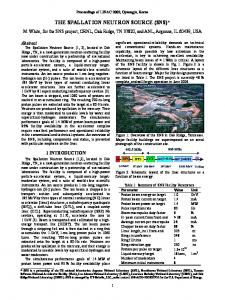
accelerator cavities operated at their space charge limits. Beam instabilities and space charge effects e.g. the influence of electric and magnetic fields on the compensation process can be studied at low and medium energies. The test of new accelerator cavity concepts will be possible downstream of the planed machine at energies of 2 MeV. First of all the new accelerator will be the driver of the Frankfurt neutron source at the SGZ FRANZ. The preliminary design of FRANZ is shown in figure1. This powerful neutron generator will deliver a quite intense neutron spectrum from the 7Li(p,n) 7Be reaction [1]. With a pulse length of 1 ns and neutron energies in the keV - range FRANZ will be well suited for a more accurate analysis of neutron capture processes and therefore the nucleo synthesis in stars and especially in red giants (s-process) [2,3]. Another and also important task of FRANZ is to study the n-capture cross-sections of those elements more accurately, which are mixed in radioactive waste. The efficiency of transmutation processes could be increased using a low energy neutron spectrum. Therefore more information of neutron cross section in the range of several keV are needed [4]. The institute of nuclear physics at Frankfurt (IKF) is involved in detector developments for large experiments like FAIR-CBM [5]. With an integrated neutron flux of 108/(cm2 s) the Monolithic Active Pixel Sensor (MAPS) could be tested on its durability against non-ionizing radiation.
Wb = 1 MeV Pb, max = 1 x 10⁴ W
Wb = 1.87 - 2.1 MeV Pb, max = 2.1 x 10⁴ W Rebuncher
Steerer RFQ
CH
Bunch compressor
p-Source Extractor Chopper Dt = 50-100ns rep. rate £ 250kHz
Rebuncher
Beam Dump Detector and Cavity Tests
RF Chopper f = 5-10MHz
Bending Magnet 7
Li Target
Figure 1: Schematic layout of Frankfurter Neutron Source at Stern-Gerlach-Zentrum, “FRANZ”
Accelerators and Facilities Ion Linacs
159
MOP051
Proceedings of LINAC 2006, Knoxville, Tennessee USA
ION SOURCE AND LEBT-SECTION
RFQ BEAM DYNAMICS DESIGN
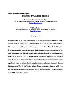
The front end of the proton linac consist of a volume type ion source using a hot cathode driven gas discharge. The plasma generator developed at IAP is able to provide a current density of j = 400 mA/cm2 [6]. For the FRANZ project the system has to deliver a beam current of I = 200 mA at a beam energy of Wb = 120 keV. The extraction system is a crucial point at this beam power in DC operation. Therefore a new pentode extraction system is developed for the ion source to deliver a high brightness proton beam with an emittance εrms,norm ~ 0.1 π mm mrad. The planned LEBT section consist of four solenoids to provide a space charge compensated beam transport and to offer enough space for beam diagnostic instrumentation as well as for a chopper and a steerer system. In between the second and third lens a magnetic chopper will be located to deliver beam pulses of around 100 ns at variable repetition rates up to 250 kHz. Beam transport simulations through the LEBT system were performed using a KV distribution and different stages of global space charge compensation. The beam envelope for the numerical transport of a 200 mA proton beam (90% proton fraction) at 120 keV and 85% space charge compensation is plotted in figure 2.
In order to minimize the RF power consumption and to design a compact FRANZ setup, two stages of RF acceleration are planned. The first stage will be a 175 MHz RFQ with an exit beam energy of Wb = 1MeV [7].
Bz,max = 0.345 T
Bz,max = 0.48 T
Bz,max = 0.48 T Bz,max = 0.64 T
Frequency [MHz]
175
Input / output energy [MeV]
0.12 / 1.0
Inter electrode voltage [kV]
100
Beam current [mA]
200
Kilpatrick Factor
1.68
Synchronous Phase out [°]
-39.18
Minimum Aperture [cm]
0.46
Cavity Length [cm]
212.31
Beam Transmission [%]
96.5
The electrode design is finished and numerical simulations using the PARMTEQM [8] code show a beam transmission efficiency of 95 % with acceptable emittance growth at the design current I = 200 mA. Phase space distributions at the exit of the RFQ in both transverse planes are plotted in Figure 4.
r / mm
Chopper
Table 1: Parameter of the RFQ design
εrms,norm = 0.58 π mm mrad
The transverse phase space distributions at the beginning and at the end of the LEBT section are shown in figure 3. The calculated emittance growth during the transport from the source to the entrance of the RFQ, εout / εin = 3 is due to lens aberrations and redistribution of the beam ions. εrms,norm = 0.37 π mm mrad
x’ / mm
x’ / mm
εrms,norm = 0.12 π mm mrad
x’ / mrad
z / mm
Figure 2: Envelope plot of a 200 mA at 120 keV proton beam under assumption of global space charge compensation of 85%.
y’ / mrad
εrms,norm = 0.51 π mm mrad
x / mm
y / mm
Figure 4: Calculated Phase space distributions of both transverse planes at the exit of the RFQ at the design current I = 200 mA. Currently design stability studies are made to check the performance of the chosen electrode geometry by varying the beam input parameters. The transmission efficiency as a function of input current and emittance leads in a feedback to an adjustment of the LEBT system. In a next step the behaviour of the RFQ with respect to thermal stress and the RF power consumption will be investigated.
CH - DTL x / mm
x / mm
Figure 3: Phase space distribution at the entrance of the LEBT section (left) and at the injection point into the RFQ (right).
160
As cw operation is needed for the second RF acceleration stage a minimization of the RF losses becomes very important. Therefore a CH cavity has been chosen as it can cooled efficiently. Triplet lenses can be partly
Accelerators and Facilities Ion Linacs
Proceedings of LINAC 2006, Knoxville, Tennessee USA incorporated into the tank for minimizing the drift space as needed for high current operation [9]. The cavity contains 6 accelerating gaps. A drift tube aperture of 24 mm was chosen as a compromise between diameter transverse acceptance and shunt impedance. RFQ exit
Rebuncher
Quadrupole lens
CH tank
2.0 MeV 200 mA 20
MOP051
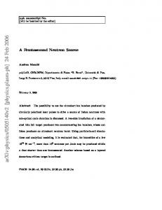
BUNCH COMPRESSOR By applying the bunch compressor concept of the Mobley type [10] for high current beams a split magnetic dipole array include edge focusing was chosen [11]. Periodic deflection by the RF chopper at one focus of the bending system guides up to 7 bunches on different paths to the final focus, where a neutron production target is located. By choosing adequate parameters all 7 bunches will overlap at the target and produce a 1 ns neutron bunch with in a time averaged intensity up to 107/(cm2s) at a repetition rate of 250kHz and at a position of 0.8 m from the target.
x, y / mm
10
CONCLUSIONS
0 - 10 - 20
0
200
400
600
800
1000
1200
z / mm
Figure 5: Scheme of the second accelerater stage consisting of a rebuncher and a CH cavity (top) and calculated beam envelops (bottom). The space charge force leads in an increase of the bunch length downstream of the RFQ. Therefore a rebuncher has to refocus the beam into the CH cavity. Table 2: Parameter of the CH cavity design Frequency [MHz]
175
Input / output energy [MeV]
1.0 / 1.8 - 2.1
Beam current [mA]
200
Effective gap voltage [kV]
200 – 240
Maximum on axis field [MV/m]
9.4
Transverse emittance growth [%]
18 εrms,norm = 0.85 π mm mrad
y’ / mrad
x’ / mrad
εrms,norm = 0.76 π mm mrad
x / mm
y / mm
Figure 6: Calculated Phase space distributions of both transverse planes at the exit of the CH cavity at the design current I = 200 mA. The beam dynamics along the CH cavity has been simulated using the LORASR code. Figure 6 shows the transverse phase space distributions at the exit of the CH section.
Accelerators and Facilities Ion Linacs
The first design studies for the Frankfurter Neutron Generator FRANZ show that these challenging project have to overcome the high space charge forces of the intense proton beam. The combination of a high current LINAC and a 1ns buncher system will allow for new experiments in various fields of research.
REFERENCES [1] M. Heil et al., “A 4πBaF2 detector for (n, γ) cross section measurement at a spallation source”, Nucl. Inst. Meth. A 459, 229-246 (2001) [2] M. Heil, S. Dabaneh, A. Juseviciute et al., “Quasistellar spectrum for neutron activation measurements at kT=5 keV”, Phys. Rev. C 71, 025803 (2005) [3] H. Nassar, M. Paul, I. Ahmad et al., “Stellar (n, γ)cross section of 62Ni”, Phys. Rev. Lett. 94, 092504 (2005). [4] G.Aliberti et al.,“Transmutation Dedicated Systems: An assessment of Nuclear Data Uncertainty Impact” Nucl. Sci. a. Eng. 146 (2004),13-50. [5] “Compressed Baryonic Matter Experiment: Technical Status Report CMB Experiment”, (2005), www.linux.gsi.de/~hoehne/report/cbmtsr/public.pdf [6] R. Hollinger, K. Volk, H. Klein, “Meassurement of the Beam Emittance of the Frankfurt Proton Source”, Rev. of Scient. Instr., Vol 73, No.2, 1027 [7] C. Zhang et al., “Development of a High Current Proton Linac for FRANZ”, EPAC’06, ID: 2342 THPCH007 [8] LANL Manual of RFQ Design Codes (LANL Report No. LA-UR-96-1836), 1996. [9] S. Minaev, U. Ratzinger, R. Tiede “Post accelerating structure with energy variation for FRANZ”, Int. Report, IAP-ACCC-120706, University Frankfurt, 2006 [10]R.C. Mobley, “Proposed Method for Producing Short Intense Monoenergetic Ion Pulses”, Phys. Rev.88(2), 360-361, 1951 [11]L.P.Chau et al., “The Frankfurt Neutron Source at the Stern-Gerlach-Zentrum (FRANZ)”, EPAC’06, ID: 2726 - TUPLS082
161