nternational Journal For Research In Electronics & Electrical Engineering
ISSN: 2208-2735
DEVELOPMENT OF AN ULTRASONIC SENSOR BASED WATER LEVEL INDICATOR WITH PUMP SWITCHING TECHNIQUE *R. S. SUNMONU 1, 2, M. A. SODUNKE 1 , O. S. ABDULAI 1 & E. A. AGBOOLA 1 1
Physics with Electronics unit, Department of Science Laboratory Technology, Moshood Abiola Polytechnic (MAPOLY), Abeokuta, Ogun State, Nigeria.
2
Department of Physics, Federal University of Agriculture, Abeokuta, Ogun State, Nigeria.
*Corresponding Author’s email :
[email protected] ,
[email protected]
ABSTRACT The quest to save electrical and water resources, we developed an automatic water level controller with pump switching system for both overhead and underground tanks. This module monitors and displays level of water in a tank. When water is at the specified lowest level, pump is automatically turned ON to refill until the tank is filled to its maximum capacity, then pump is turned OFF thereby saving both inadequate electrical and water resources. The design consist of Power supply, microcontroller, sensor, display and pump units. Arduino UNO, a microcontroller, which is commercially available, is replaced with a cost effective, electronically and environmentally rugged assemblage from available cheap components. The 20kHz ultrasonic distance sensor, remotely senses level of water by measuring length of emptiness or fullness of the tank from recorded time of arrival of echo from water surface. This length is interpreted and displayed by programme based microprocessor in percentage (%) of the capacity on Liquid Crystal Display (LCD) unit. KEYWORDS: Echo, LCD, Ultrasonic distance sensor, Programmable microprocessor, Water conductivity, Water resources
I.
INTRODUCTION The facility requirements in many industries, farms, hostels, hotels, offices include an
overhead tank for water, which is usually fed through an electric pump that is switched OFF when the tank is filled up and switched ON when it is empty. So, the most common way of knowing when the tank is filled is by observing when it overflows the brim. Depending on the type of liquid being handled, overfilling of such a tank could lead to a great liquid material losses ranging in the order of thousands of Naira per week depending on the extent of such application. These losses can be prevented if the tank is monitored automatically by incorporating a feedback Volume-3 | Issue-5 | May,2017 | Paper-1
1
nternational Journal For Research In Electronics & Electrical Engineering
ISSN: 2208-2735
monitoring mechanism which would be capable of stripping the pump ON or OFF accordingly. Although pumps with variable speed motors could be more efficient than ON/OFF mechanism, but the former are expensive to get and maintain especially for homes and small(or medium) applications in Africa and other developing countries. More so, commercially available water level sensors are expensive being imported into the country and as such cannot be used in many homes and facilities. Sustainability of available water resources in many areas of the globe is now a major issue. This has much to do with poor water allocation, inefficient use, lack of adequate and integrated water management. Water is indispensible input in agriculture, industries and homes. Therefore, efficient use and monitoring of water are critical in proper water management. Moreover, the common method of water level control for homes and offices is simply to start the feed pump at a low water level and allow it to run until a higher water level is reached in the water tank. Proper monitoring is necessary to ensure water sustainability and disbursement linked to sensing and automation, and such program based approach entails microcontroller based automated water level sensing and controlling [12]. More importantly, advancement of control system in engineering have created different ways in which automatic switching systems can solve water management problems in homes and industries especially in the developing countries. This control system has an automatic pumping system attached to it so as to refill the tank once the liquid gets to the lower threshold, while switching off the pump once the liquid gets to the highest threshold [Leigh.D, (2003)] The aim of this present work is to develop an independent water level control system with design based on ultrasonic transducer (sensor) thereby addressing problems of untimely response and frequent breakdown of contact sensors due to surface coating and corrosion from the water medium which characterized existing water level control based contact sensors. Our developed system controls, monitors and maintains the water level in the tank (overhead or surface ) and ensures the continuous flow of water round the clock without the labor stress of manually switching the pump ON or OFF thereby saving time, electrical energy, water, and prevent overworking of the feed pump.
II.
PROBLEM DEFINITION OF PROPOSED WORK The conventional water level indicators waste time, electrical and water resources because of
the manual mode of level monitoring and switching of the feed pump. The existing automatic Volume-3 | Issue-5 | May,2017 | Paper-1
2
nternational Journal For Research In Electronics & Electrical Engineering
ISSN: 2208-2735
water level indicators suffer limitations because of the low response rate and frequent breakdown of contact sensors. Arduino UNO, an active microprocessor in this design is commercially available which is electronically and mechanically fragile, hence the needs to replace Arduino UNO with rugged and cost effective fabricated units from available cheap components. In Nigeria, there are no known realized circuitry for the water level sensing and control till date as such devices are usually imported[2]. This paper looks into the development and implementation of such a simple and cost effective feedback regulator for use in applications where there are needs to real timely monitor the water levels.
III.
DESIGN OF THE AUTOMATED WATER LEVEL SYSTEM
A. Description of Liquid Level Regulator System The entire system is a closed loop automated device as shown schematically in Figure 1.It uses liquid level as input to control power supply to a liquid pump. Liquid level will be monitored using a immovable and non contact ultrasonic sensor placed strategically to detect and determine the present level of the liquid in percentage volume. The output signal from the receiver(R) of the ultrasonic sensor is fed into the electronic circuit, where such signal is transduced into ON or OFF signal that trips the power supply to the pump.
Figure. 1:
Schematic Diagram of the Entire Water Level Indicator/ Regulator
Volume-3 | Issue-5 | May,2017 | Paper-1
3
nternational Journal For Research In Electronics & Electrical Engineering
ISSN: 2208-2735
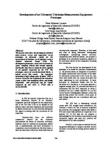
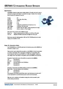
B .Ultrasonic Sensor as Liquid Level Regulator The two traditional ways of locating the level of water in a tank are either by tapping down the side of the tank until the sound suddenly changes, or by removing the tank cover and dipping in a measuring stick [1]. The first method is notoriously unreliable, while the second method can be awkward and time consuming,. A more sophisticated and advanced approach to the sensing of the water level in a tank utilizes various electronic circuitry developed and deployed for water level sensing [1] based on integrated circuit technology and the output signal from a water sensor can be harnessed in a form suitable for regulating the level. Using electronic devices to achieve ON /OFF switching is not an entirely new thing. According to [11] who captured an informal version of the evolution of the microprocessor, the transistor developed by Bell Laboratories in 1947 was intended to replace vacuum tube to switch electronic signal on or off. It was, however, not until 1950 that integrated circuit (IC) was developed at Texas Instruments. In this present work, ATMEGA 328PU as an IC plays specialized role in the circuitry. Ultrasonic sensor works on the basic time-of-flight principle which state that sending a sound wave from a piezoelectric transducer to the contents of the vessel which may be liquid, solid or slurries. In the case of liquid level controller/indicator, liquid level can be determined by measuring the trip time difference between a transmitted ultrasonic pulse and a reflected echo.
The liquid levels determination is done by electronically converting the time of arrival of echo as recorded by the receiver (R) of the ultrasonic sensor from incident waves from transmitter (T) as shown in Fig. 6. It is known that sound travels through air at about 344m/s(1129ft/s),The total distance (D) the travelled by the sound wave from the transmitter(T) to get water surface and back to the receiver (R) of the ultrasonic sensor ( as shown in the fig. 1) can be determined by taking the total time(t) for the round trip distance(to and fro) and multiply it by speed(s) of sound waves in air, which is 344mls (or 1129ft/s). In short, we can write D = t x 344 (or 1129)
(1)
Note that the round trip distance means that the sound wave travelled two times distance (to and fro liquid level) before it was detected by the receiver (R) of the ultrasonic sensor. The actual distance, d from which we can compute the liquid level (Volume) is obtained from: Volume-3 | Issue-5 | May,2017 | Paper-1
4
nternational Journal For Research In Electronics & Electrical Engineering
d=
𝑫
ISSN: 2208-2735
(2)
𝟐
The shape of the tank containing the liquid determines how we compute the volume. In this work, we consider cylindrical shape and as such the volume (V) is computed using Volume, V = 𝝅r2h
(3)
The r is the structurally measured radius of the circular section of the cylindrical tanks, h, which is the height of the cylindrical tank and will be taken as the actual distance, d obtained above. Then, we can write V = 3.14 xr2d
since
𝝅 ≈ 3.14
(4)
These parameters (r and d) will be treated as inputs to a programmable unit of the module as implemented by Arduino IDE. More so, for convenience, the level and volume is expressible in percentage of the maximum volume using the equation: Volume in Percentage =
𝑫𝒆𝒕𝒆𝒓𝒎𝒊𝒏𝒆𝒅 𝒗𝒐𝒍𝒖𝒎𝒆 𝐌𝐚𝐱𝐢𝐦𝐮𝐮𝐦 𝐕𝐨𝐥𝐮𝐦𝐞
x 100
(5)
All these numerically stages are implemented electronically and final results: real time volume (liquid level) in percentage (%) is display on the Liquid Crystal Display (LCD) unit of the module.
IV.
CONSTRUCTION MATERIALS FOR THE WATER LEVEL INDICATOR
The module is fabricated out of available active and passive components. Some of the components: (a)
Factory/Commercial Arduino UNO is replaced by rigged and cheap assembly of ATmega
328PU with IC socket, crystal oscillator, 22pF capacitor and 1KΩ preset resistor. Arduino UNO consist of both a physical programmable circuit board called microcontroller and a piece of software, or IDE (Integrated Development Environment) that runs on your computer, used to write and upload computer code to physical board An Arduino UNO is a commercial microprocessor board based on the ATmega328P, which is an 8-bit microcontroller with 32KB of Flash memory and 2KB of RAM, It contains everything needed to support the microcontroller: simply connect it to a computer with USB cable or power it with an AC-to-DC adapter or battery to get stated
Volume-3 | Issue-5 | May,2017 | Paper-1
5
nternational Journal For Research In Electronics & Electrical Engineering
(b) Others
ISSN: 2208-2735
materials (electronic and electrical) are Buzzer, Relay, Capacitor, Resistor,
Transformer, MQ2 Sensor, Liquid Crystal Display(LCD). The entire module has 5 parts/units which are: Sensor unit, Control unit, Display unit, Power supply unit and Pump control unit. For simplicity and convenience, separate unit is systemically built by fixing and soldering the required components on the boards. These units are thereafter coupled using the integrated circuit diagram as shown in fig.2. In this design, it is required that the pump stops working when the water level reached a certain level and it starts working when it reduces to certain level. In order to achieve this, we take advantage of the conductivity of water or any other liquid that has an appreciable level of electrical conduction [17]. For the operation of the module, 12V d.c which was properly rectified from high voltage mains a.c. was sent to the input while the output is grounded through 100KΩ resistor by a point wire. The 12V d.c would not be complete its electrical path unless there is a signal from control. The required signal gets to control unit only when there is water in the tank, as such another point wire must be positioned at a desired height/level for contact with water and this wire is connected to the control pin. As a result, when there is no water in the tank, the connection to the control unit (pin) is open circuited and the resistor pulls down the voltage. As the liquid level increases, the liquid gives an electrical continuity which generate a signal at the control unit. Once the signal is generated, which in turn create positive voltage at one end of the resistor. This positive voltage is then used to trigger the base region of the transistor, which in turn triggers the a relay that is able to switch the pump ON/OFF.
Volume-3 | Issue-5 | May,2017 | Paper-1
6
nternational Journal For Research In Electronics & Electrical Engineering
ISSN: 2208-2735
Figure 2: Circuit Diagram of the Water Level Indicator
Figure 3: shows the assemblage components for the 4 units of the Module
V.
Figure 4:Shows the entire system with the Control Units.
CALIBRATION AND PERFORMANCE EVALUATION OF THE LIQUID LEVEL INDICATOR On order to achieve high level of accuracy of our developed module, the module at the point
of installation must be calibrated. The acceptable error margin of 0.17% by maximum is evaluated. This is error could be attributed to fact that temperature and humidity of the environment and the position of the ultrasonic sensor affect the accuracy of the ultrasonic sensor[19]. More so, for performance evaluation of the system, it was connected to 12V, 5amp electric water pump. The maximum was set at 99.83% whereas the minimum was 0.17% of the volume holding capacity of the tank. The pump was connected through the control unit while the ultrasonic sensor was strategically positioned above the water inlet level and free from uncontrolled turbulence of the water from inlet. As soon as the water level attained the programmed highest level, the control unit switched OFF the pump. In case of lowest level testing, water is drained continuously until the lowest level was reached, then the control unit switched the pump ON. Volume-3 | Issue-5 | May,2017 | Paper-1
7
nternational Journal For Research In Electronics & Electrical Engineering
ISSN: 2208-2735
It is interesting to know that we can fix the lowest level of the water at around 50% of the volume holding capacity of the tank so that the system can always maintain water level. Thus, the module real timely regulates water level between these two situationally determined limits as long as there was power supply to all the units working as a system.
Fig. 5: Shows the system ready for System
Fig. 6: shows the Transmitter (T: up) and
Calibration
VI.
Receiver (R: down) of the Ultrasonic sensor
RESULTS
An ultrasonic sensor based water level indicator was developed and constructed using available components and materials and it is successfully tested. The electronic circuitry was realized, especially by replacing the factory based, commercial and fragile Arduino UNO with cost effective and electronically rugged assemblage. A transparent cylinder vessel was used as a water tank model to test the developed system. The non contact ultrasonic sensor is strategically positioned on the peak of the vessel thereby solving the problems of frequent replacement of contact and submersible sensor which characterize existing commercial and expensive water indicator. The module detected, controlled and maintained the level of water. The level of the water in the vessel is indicated in % of the volume holding capacity of the tank which is displayed on the Liquid Crystal Display (LCD) unit as shown in fig.7.
Volume-3 | Issue-5 | May,2017 | Paper-1
8
nternational Journal For Research In Electronics & Electrical Engineering
Figure 7
VII.
ISSN: 2208-2735
50.81% of Volume displayed as output on the LCD
CONCLUSIONS AND RECOMMENDATIONS
The testing and performance evaluation of the system showed that it can regulate water level within the specified limits. These limits are usually determined by factors such as rate of electric power availability and rate of water usage. The successful development of this electronically rugged and cost effective module would be useful in industries, small and medium scale enterprises, farms, homes, laboratories and other applications where it is economical to save electric power, labor, time and water (and other ionic chemicals) stored in overhead and underground tanks.
VIII LIMITATION / FUTURE WORK This developed system can only indicate and maintain water level. However, knowing the status of the source of water/ liquid (that is whether there is water or not at source) is still a challenge. If there is no water at the source, the water pump would start running unnecessarily and overheating of the pump set in. This limitation can be addressed by incorporating another sensor [17].This can form the basis for future work to improve on this design.
Volume-3 | Issue-5 | May,2017 | Paper-1
9
nternational Journal For Research In Electronics & Electrical Engineering
ISSN: 2208-2735
REFERENCES [1]
Anon. Water Level Sensor.Accessed
from
the website:
http://www.siliconchip.com.an/cms/A.30607/article.html on 15th May 2009 [2]
Antanwu C.N., Mbajiorgu C. C. and Anoliefo E. C. (2012), Design and Implementation of a Water Level Controller. Nigerian Journal of Technology, Vol. 31,No, 1
[3]
Aye, T. S., & Lwin, Z. M. (2008). Microcontroller Based Electric Expansion Valve Controller for Air Conditioning System, World Academy of Science, Engineering and Technology.Vol.42,pp 387-391.
[4]
Belone, S., & Graw, H. W. (2004).Electronic Circuit Discrete & Integration, (23rd Edition).
[5]
Byrne, L., Lau, K. T.,Diamond, D. (2002).Monitoring of Headspace,127(10),pp.1338-41
[6]
Cara Elmer, H. Schweinzer, H (2004) Ultrasonic Distance Measurement system.
[7]
Dietz, P., Yerazunis W., & Leigh, D. (2003). Very Low-Cost Sensing and Communicaton Using Bidirectional LEDs,.Mitsubishi Electric Research Laboratory Inc.
[8]
Dorf, R. C. and Bishop R. H. ,(2005) Modern Control Systems, 10th ed. Upper Saddle River, NJ: Prentice-Hall.
[9]
Eggebrecht, L. C., (1990) Interfacing to the IBM Personal Computer, Second E dition,''
[10]
Frank Massa.(May 1992) ‘Ultrasonics in Industry’, Fiftieth Anniversary Issue, Proc IRE.
[11]
Garetz, M.(1985) Evolution of the Microprocessor: An informal History,Byte,10th Anniversary Issue
[12]
Lau, U., & Dermot, D. (2005).Sensors Operation, London Chand Company.
[13]
Lee De Forest (1907) Ultrasonic Distance Measurement system.
[14]
M. Javanmard , Abbas, K. A., & Arvin, F. (2009). A Microcontroller-Based Monitoring System for Batch Teas Dryer, Journal of Agricultural Sciences, Vol.1,No. 2.
[15]
Noor Farizabt.Ariffin, Norfazilahbt.Ja’afar (2004). “Development of Intelligent Distance
[16]
Donald P. Massa (2011) Choosing an Ultrasonic Sensor for Proximity or Distance Measurement, Massa Products Corp.
[17]
Sanket Shukla ,Amit Saxena ,Sadiq Ali Khan, Rohit Sharma & Rohit Kanyawal (2006),Automatic Water Level Controller for Residential Applications,Int.Scientific Research and Management,Vol. 2.Issue 2,pp.457-86
[18]
Ugata, K. (2002) Modern Control Systems, 10th ed. Upper Saddle River, NJ: PrenticeHall.
Volume-3 | Issue-5 | May,2017 | Paper-1
10
nternational Journal For Research In Electronics & Electrical Engineering
[19]
User
guide,
Ultrasonic
sensors-RET
ISSN: 2208-2735
Automation
Control
www.retautomation.co.za/ultrasonic [20]
Wells, R. L., Schueller J. K. and Tlusty.J. (1990). Feed forward and Feedback control of Flexible Robotics Arm,IEEE Control System 10(1),pp.9-10.
[21]
William, J. Fleming (2001).Overview of Automotive Sensors. IEEE Sensors Journal, Vol. 1, No.4, pp.297-308
Volume-3 | Issue-5 | May,2017 | Paper-1
11