and chronometers. .... Brachner also illustrates (p.379fl Brander's dividing apparatus. .... It could be used to measure the colour and brightness of stars by adjusting the ... with separations as fine as 0.0001 inch We know something of the form of .... Conical shaped diamonds were the same time, Holtzapffel described how.
Diamonds in Instrument Making Randall C. Brooks Diamond tipped tools have been used in precision machining and scientific instrument making longer than one might imagine to finish precision surfaces and to draw the finest lines. Diamonds were first employed as tools in the mid-17th century to delineate lines on glass for micrometers and in the 18th century for precision machining such as f i s h i n g and polishing precision screws for dividing engines. In the 19th century diamonds were used to engrave plates for illustrations and to make threads on glass bottles where the cutting tool was a 'metal disc revolving rapidly on fixed centres and having an angular edge fed with emery and water; in some rare cases a diamond is used as the cutting tool'.' Diamonds were also used to drill holes in rubies or sapphires for pivots of watches and chronometers. Holes were volished using a steel wire and diamohd dust suspended in olive oiL2 Scientific instrument makers thus pioneered techniques which became important for industrial processes. Beyond their use in jewelry, most of us probably next associate diamonds with their use in the pickups of recond player tone arms or in industrial equipment utilizing their hardness such as drilling bits. But they are commonly used as cutters for light work on high speed turret lathes where high production rates are necessary for shaping hard rubber, bakelite, pressed carbon, aluminium or brass. They are only capable of light cuts but, by the beginning of WW 11, could be run at speeds in excess of 5,000 surface ~ modern uses feet per ~ n i n u t e !Other include dressing grinding wheels and diamond gauging points used to determine whether dressing is, in fact, neces~ary.~ Tools and Machining Processes The high degree of polish and finish on many adjusting and micrometer screws on scientific instruments made from the mid-18th century confirms that there was a final stage of production beyond cutting on a lathe with a steel cutting toole5 Henry Hindley used such a technique to grind and polish the worm and wheel of his scale dividing engine in 1739.6A piece of soft wood was charged with a grinding powder held against the thread. The wood, being soft, deformed to the thread form and the dust became imbedded in the grain of the wood (similar in principle to the use of pitch and optical rouge for lens polishing) thereby polishing the thread. By the early 19th century very fine pitched
Fig.1 Ramsden's screw cutting lathe with which he made the worn screws for his linear dividing engine (1774) and circular dividing engine (1775). mircometer screws were polished with pitch, charged with diamond dust, which deformed to fit any thread profile. However, it was only towards the end of the century that the technique was recorded. The methods adopted by Taylor, Taylor & Hobson beginning c. 1888, to make threads for optical components were adapted to make bench micrometers, camera lens mountings and, later, high precision binding screws for the aircraft industry. Several standard methods originated in the Leicester firm for production of fine screw threads including use of diamond dust to maintain the shape of cutting tools. On the spindle used to-day for milling accurate screw threads, there are two little circular cutters with the Whitworth thread form lapped at their edges, which are notched radially to present cutting edges. The lapping is done on a special machine by means of a diamond-charged rotating annulus with an eccentric motion so that it maintains its surface in a true plane. This ~ M ~ u grinds S the sides of the thread cutters perfectly straight and to the correct an le, and rounds the crest in a circular arc
B
Such equipment was the progenitor of the modem thread grinding machine to manufacture precision screws on a routine and rapid basis.8 The first person to use diamond tipped metal cutting tools was Jesse Ramsden while constructing his linear dividing engine (1774).9From Ramsden's description, produced to fulfill conditions of a
Bulletin of the Scientific Instrument Society No. 47 (1995)
Board of Longitude Prize, we learn of his method for producing and using screws and diamonds.1° Success of his dividing engine depended on a tangent screw or worm and to make it, Ramsden made a screw lathe (Fig.1) incorporating a lead screw mounted on a triangular bar. A triangular shaped, diamond tipped tool was advanced by the lead screw by turning a hand crank acting through change gears. Two worms were cut - one with teeth to act as a cutting tool to form the thread on the edge of the wheel and the other to be used in the dividing process. Ramsden made the screws of steel which were then hardened. To correct the errors caused by the hardening process he 'finished' the thread by recutting it with the diamond tipped cutting tool." This technique was also applicable to micrometer screws since the hardening process often rendered such screws distorted and with irregular pitch. It became common practice to return hardened screws to the original lathe and refinish the thread with a grinding disc tool to remove errors due to hardening. John Barton was able to turn a cylinder down to an accuracy of 1/12,000 inch for Edward Troughton using diamond tipped tools. In 1805 Barton also turned the deferential threads (92.7 and 102.3 P I ) for his 'Atometer' with a diamond tipped tool, according to a letter to Matthew Bolton which is in the Library of the Science Museum. Turrell stated that diamond tipped tools were always used in conjunction with slide rests on a 17
his micrometers is somewhat variable and the lines are about 0.02 mrn wide (Fig.2). Under magnifications of 500 and 2000 times they show striations from the cutting tool which was an unfinished diamond." The striations are 0.0020.004 mm wide and 0.001-0.002 mm deep. These glass micrometers were often made in sets and were used on telescopes, microscopes, surveying levels and distance finders. Brander's ruling engines do not appear to have survived, but are described and illustrated in Brachner.
4
+
1
The Duc de Chaulnes' microscope micrometer (c. 1765) was mounted on a frame which held samples for inspection; the frame incorporated a second micrometer for moving the stage for direct measurement of the sample.18 This arrangement was used in conjunction with a small glass scale scribed by a diamond to test one micrometer screw against the other and to set up a table of errors for the screws - a noteworthy event in the early investigation of instrumental errors. About 1774 John Coventry displayed several of his grid micrometers to the Royal Society. These were primarily intended for use with microscopes and appear to have been the most frequently referred to microscope micrometers of the late 18th century. His early versions had 50 lines to the inch but Coventry proceeded to improve them to 100 and then to 1000 per inch. Nothing has been found describing Coventry's ruling engine but it is known that he used a fine diamond for the ruling.19
Fig.2 Measurements of line spacings of two glass micrometers ruled by Brander. They are illustrated in Brachner (1983, p.178 and p.313). Brachner also illustrates (p.379fl Brander's dividing apparatus.
lathe and were capable of turning hardened steel with facility.I2 Dividing scales on circular dividing engines, where the bearings of the wheels are not perfectly circular or concentric, results in scales that reflect those errors. In several engines, rollers supporting the dividing wheel ran on inset steel rings and it was common for 19th century steel to have 'knots' of abnormally hard material; instrument makers were advised to use a diamond point to finish these surfaces. Similarly, noncircular bearings or non-flat bearing surfaces in astronomical or geodetic circles caused observational errors. The 5-foot mural circle at Armagh, made by Thomas Jones when installed in 1832, had a 20" error of eccentricity.Jones went to Ireland, removed and reground the pivot and redivided a segment of scale which was also in error. However, in November 1834, Jones again had to regrind the pivot but this time he used a diamond tool and redivided the circle in situ also with diamond-tipped tools.13 18
Ruling Glass for Micrometers Applications of diamonds in the aid of science may be traced to the mid-17th century. The first recorded use (1649) was by Eustachio Divini who employed diamonds to rule a net of lines on the curved surface of a convex eyepiece lens intended as a micrometer. Petite, Balthasar and Pierre de LaHire used diamonds for preparing grid micrometers.'" Nicholas Bion described the replacement of wire crosshairs in telescopes: "Note, these lines must be very lightly drawn upon the Glass with a small diamond whose Point is very fie".15 A succession of other makers followed these leads including Benjamin Martin, Georg Brander, Duc de Chaulnes, John Cuff, John Barton, Joseph Fraunhofer, Alfred Nobert, Lord Rayleigh and Henry Rowland. George Brander used a ruling engine in c. 1760, though crude by later standards. With this machine he was capable of making quite finely drawn scales in a number of patterns.IbThe line spacing of
b
1
Ezekiel Walker published a description of a grid micrometer conceive about 1805; . . these were made for him by W~lham Cary of London and by Miller & Adie of E d i n b ~ r g h .Brewster ~~ described them (1813) erroneously indicating that lines were on mother of pearl. Walker published a correction indicating the lines were in fact drawn on glass and claiming to have made examples with a grid of lines 0.001 inchapart and drawn at right angles.21 He settled on lines separated by 0.01 inch for use with microscopes or telescopes. Walker's engraving method was not described.
4
A link between Brander's glass micrometers and the superb microscope test plates of Nobert a hundred years later was the net micrometer of Joseph Fraunhofer. Designed to be an improve-. ment on the 'rhomboidal' micrometers of Bradley, LaCaille and Wollaston, it consisted of a glass disc divided by many parallel lines with a second set engraved obliquely to them.22These were illuminated with a small lamp. Accord-
Bulletin of the Scientific Instrument Society No. 47 (1995)
I
.
and were used for engraving and for ruling metals. For ruling on glass a rounded natural edge was found best; these "split" the glass rather than scratch it and left a very fine line; a sharp-edged diamond left glass splinters and a line with irregular edges. To rule the scales of astronomical and similar instruments, Turrell found diamond splinters with a fine acute edge better than the obtuse angles of natural diamonds. He also supplied diamond slivers to Andrew Ross for use with his dividing engine. Ross was able to divide 10 circles on platinum to 'A0 with one diamond piece before it was accidently broken. A steel point might have divided a third of a circle according to H~ltzapffel.~~
-
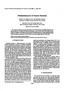
Bands on 7 . 5 2 ~spacing with 11 finely
Fig.3 Nobert's glass grid 'photometer' micrometer which incorporated bands of closely spaced lines. It could be used to measure the colour and brightness of stars by adjusting the angle and brightness of its illuminating source. ing to Pearson, Fraunhofer developed a ruling engine with which to rule lines with separations as fine as 0.0001 inch and with which the angle could be set at any desired.23 A related instrument made by Fraunhofer was his concentric circle micrometer which was used by J. von Soldner for timing stellar transits. The discs were made by drilling a small hole in a piece of glass and drawing several concentric circles about it. They were engraved on a lathe with a diamond-tipped tool mounted in a cross slide. A number of observers had used circular diaphragms, but Fraunhofer extended the usefulness by including 11 circles on the same glass This form became very popular on the Continent. The main problem was lack of an eyepiece which could focus over a sufficiently large field to include all of the engraved circles. The most clever glass grid mocrometer was that of Alfred Nobert made in the mid-19th century (Fig.3).25It consisted of lines drawn in 5 bands of 11 lines with each band separated by 15" when viewed through a telescope. Each band was 1/300 Paris inch (7.52pm) wide - the width of a common micrometer filament. The line separation was 0.736pm. A special property of this arrangement was that tilting the angle of illumination changed the colour of the bands, i.e. Nobert made use of the diffracting properties of the closely spaced lines. This colour changing property could be employed to measure the relative colours of stars by measuring the angle of the illumination or, by altering the distance of the illumination, a simple photometer was also created. Hence this instrument could perform three functions with some simple adjustments.
Shaping the Diamonds
I
We know something of the form of diamond points used by John Barton and Peter Kier from the extensive review of diamond use by T ~ r r e l lThe . ~ ~shapes are illustrated in ~ i ~ . David 4. Brewster requested that Barton make a grating with 2000 lines/inch but the diamond stylus broke after a large portion was completed. Brewster's ruling was never completed and Barton did not attempt an~ther.~' Barton had observed that the interior of a diamond was softer and more susceptible to breaking and he had used long oval shaped diamonds to tip his turning tools.28 But, with this experience, he switched to natural, rounded, uncut diamonds. It has been suggested that ruled specimens (5000 lines/inch) by Robert Bate may actually have been made on Barton's engine c. 1826. Turrell described the properties of natural diamonds noting that those which had been ground caused glass to splinter but that he had made rulings on crown-glass with natural diamonds with great succ e s ~ Conical .~~ shaped diamonds were made on a lathe using another diamond
l2OC3
Front View
Side B550 View
Kier's Diamond Points
Mayall described Friedrich Nobert's method of cutting diamonds and even this great craftsman had difficulty with points breaking. Nobert used a ruling force of only 3-30 grams depending on the number of lines required per i n ~ h . 3 ~ He used fragments salvaged from a diamond cleaver choosing chips which would allow a 1/16-1/20 inch long edge to be cut where chosen. One face was ground to an angle parallel to a cleavageface. The chip was then cleaved to create the other face of the point rather than grinding it since that procedure left the point rounded. Nobert wanted a perfectly sharp point for ruling glass and replaced diamond points when glass fragments began to appear around the ruling point. After 1869 he used 'mild' (i.e. soft) glass, to help avoid this problem. Later in the century, a simple hand operated device was described by the Rev. D.W. Smith which had been exhibited before the New York Microscopical Society (Fig.5).32 TO rule lines finer than 40-50 per inch he concluded that the selection of the diamond point was more im~ortantthan the machine. a perspective 'few instnment makers would have agreed with. Nobert mounted his diamonds in a notch in the end of a piece of brass wire. About the same time, Holtzapffel described how diamonds could be mounted in a split
0D
Front View
Side View
Barton's Diamond Points
Fig.4 Shape of the diamond tips used by Barton c. 1820. He preferred rounded natural tips but these gave way to the shape of tips used by Kier and Nobert.
Bulletin of the Scientific Instrument Society No. 47 (1995)
19
resolution of spectra of their spectrographs. Fraunhofer was able to take the division of glass a step beyond those of his predecessors by controlling the depth, breadth and symmetry of the angles of the grooves. Samples with upwards of 30,000 lines per Paris inch were made but Sir John Herschel found that examples with more than 8,200 per Paris inch did not yield pure spectra due to uneven spacing of the grooves. Brewster found that Barton's examples of 10,000 lines per inch provided excellent spectra but he was still envious of Fraunhofer's gratings and the research he was able to carry out with them.41 Fig.5 Smith? 'ruling engine' was a model of simplicity compared to the impressive grating engine of Rowland. Smith's was to rule grids of 40-50 lines per inch and he found the sharpness of the diamond tip to be more critical than the precision of the screw - the reversefor gratings with up to 43,000 lines per inch. wire or in a hole drilled in the end of a thin brass rod with the hole pinched around the largest part of the diamond and held in place by shellac or brazed into position; the latter technique is still used. He also noted that the outside layers of a diamond produced superior results compared to chips or 'diamond bort1.%The best of all were carbonate diamonds from Brazil which were used for turning emery wheels and grindstones; indeed diamonds are still employed to dress grinding wheels to maintain their forms for precision work."
the engraving process.38A 20 TPI screw was used for the longitudinal motion, and was controlled by a 500 tooth ratchet wheel providing a maximum resolution of 0.0001 inch excluding screw errors of ~ 0 . 4 % :This ~ machine was not intended for precisely dividing equally spaced divisions and the buttons created diffraction phenomena even if lines were not equally spaced, though the quality and brilliance of spectra was reduced. An optical analysis of extant Barton's buttons would provide useful information on the functioning of this machine.
Origins of Spectral Gratings
Barton, Comptroller of the Mint, was acquainted with Henry Maudslay through their business activities for the Mint.35 In 1810 they each made a precision screw of exactly the same pitch and 15 inches in length. These were compared and "were found exactly to agree throughout their length and were considered perfect." Holtzapffel stated that Barton used a diamond tipped tool to execute There is a machine in the Science Museum associated with Barton for making 'Barton's buttons' which utilized gratings to produce spectra for decorative purposes. The workmanship of the machine is certainly consistent with Maudslay having been involved.
Fraunhofer began making gratings on glass (c. 1820) first covered with gold-leaf and then grease or varnish. The maximum number of lines he could obtain with the gold-leaf covered glass was 1000/inch above which the gold-leaf was scraped off. Double that number could be formed on glass coated with a thin film of grease but this was still short of the number he wanted. Fraunhofer found that grooves made in the surface of glass with a diamond point best produced the phenomena he sought. The maximum number of lines he was eventually able to produce with equal spacing was ~8200/inch.He achieved line spacings as small as 3.3-16pm but no description of his dividing or ruling engine has been found.
After Barton had obtained a patent for his reflecting buttons, c. 1822, the machine was modified to carry several blanks in order to produce more buttons to fill the commercial demand. Barton also made buttons in steel duplicating them with stamping technology familiar in the Mint.37The 'button' machine could engrave 6 samples simultaneously and diamonds found in its drawer support Barton's use of diamond tipped tools for
Fraunhofer observed that one grating gave brighter spectra on one side of the primary image than on the other.40He interpreted this to indicate that one side of the grooves was sharper or inclined more than the other due to the form of the diamond point. Tests with grease gratings proved the latter to be the case. This was the origin of 'blazed' gratings used by astronomers to maximize efficiency for a particular order and
20
'
One of the most talented makers of the 19th century was the German, Friedrich Adolph Nobert. The son of a clockmaker, Nobert took up this profession aspiring to greater heights by designing various watches and chronometers surpassed in Germany only by those of Kessels. Nobert obtained a bursary to attend the Technical Institute in Berlin and in his first week learned dividing techniques. With this knowledge he made his own dividing engine which is believed to be the one he used to cut chronometer gears and to rule diffraction gratings, test plates and ruled scales for astronomical instruments. After his training in Berlin, Nobert became technician and instrument maker at the University of Greifswald (1835) but returned to Bath after his father's death in 1846. He is perhaps best known for making the gratings used by Angstrijm in his important studies of spectra. Nobert turned his interest towards tests of microscope optics in 1845 when it occurred to him that dividing engines could be used to make test, objects engraved on glass. The idea was drawn from Fraunhofer's gratings. In 1846 Nobert made his first a test plate consisting of 10 bands with line spacings ranging from 1/ 1000-1/4000 Paris line (2.256-0.564pm) in a geometrical progression. This was the first target with known spacing for testing the quality of microscope optics; telescopes had been -tested by observation of close double stars for many years but no equivalent existed for microscopes. Over the years Nobert made 7 different test plates culminating with the 'new' 20-band plate of 1873 which amply demonstrated his talent. The lines of the finest band were separated by just IIOO-~IOOA. This resolution was beyond that of optical microscopes but was finally resolved in 1965 by Bradbury and Turner using an electron micro~cope.~~ The basis of Nobert's ability to make these test plates was his circular dividing engine and his use of a diamond point.
Bulletin of the Scientific Instrument Society No. 47 (1995)
,+,-I
The dividing engine Nobert used for most of his career is in the Srnithsonian Institution. The dividing plate is 12 inches in diameter and is ruled to 5' on a silver scale imbedded near the limb. Although it is a circular dividing engine, Nobert could use it to produce his straight line test plates and gratings by using the radius of the dividing plate as a lever arm. The arrangement for carrying and adjusting the diamond point is specially ingenious. The questions to be solved were - (1) to provide means to adjust a diamond edge to any angle within required limits; (2) to balance it truly so that the weight-pressure for ruling could be perfectly controlled; (3) to raise and lower it strictly in one plane that is to say, mechanically free from lateral play, so that the consecutive divisions of the ruling depended solely on the motion imparted to the glass plate by the dividing engine; (4) to cause the diamond to oscillate freely in one plane; (5) to control the length of the lines to be ruled; (6) to connect the whole mechanism to insure an even rate of speed in the ruling movement of the diamond.
Nobert divided his test plates and diffraction gratings by using micrometer microscopes and the graduations on the divided plate of the engine and adjusting the position visually for every line cut. Mayall continues: Imagine the task of adjusting the divisions under the micrometer-microscope,winding up the train of wheels, lowering the diamond on the plate, starting the train, watching for a possible vibration in the mercury bath during the actual ruling, which might ruin the scientific value of the plate, then lifting the diamond by the excentric roller preparatory to recommencing the whole operation - 12,000 times in succe~sion!~~
Lord Rayleigh (1874) carried out some experiments in making reproductions of gratings using a callodio-chloride process in which he used gratings of 3000 and 6000 lines on a square of one paris inch made by Nobert and one by Rutherford of 6000 lines to the inch. He found Nobert's much suverior thoueh the 3000 line version demdnstrated t g e e distinct zones attributed to use of three different diamond points. Visible to the unaided eye, he also found that these three zones were reproduced in the copies. Rayleigh y a s able to observe almost all of the lines Angstrom had plotted in his solar spectrum with both the 3000 line original and its copy; he also noted that the third order spectrum was the brightest. With the techniques of diamond ruling largely perfected, the limiting factor in achieving optimal spectral grating performance became the quality of the
engine screw. The screw for Henry Rowland's ruling machine was made by his university's instrument maker, Theodore Schneider,+' and was, according to Rowland, accurate to 0.00001 inch with no detectable periodic error. Rowland produced gratings with 43,000 and 29,000 lines per inch and with a total of 160,000 lines!45Contemplating the cost to make telescopes for use with such large gratings, Rowland realized that the grating could be made on a curved surface to focus the spectrum directly. Modified to make curved gratings, this machine could produce gratings of 6.25 x 4.25 inch (instead of 6.25 x 6.25 for flat gratings) capable of splitting hgstromfs .lme 1474 of the solar spectrum. Rowland was also able to blaze the rulings for a specified spectrum order, e.g. the grating he made for Langley's study of infrared spectra which had a more concave surface than usual. Rowland found that the diamond cut differently on different parts of curved plates. It is a fortunate coincidence of nature that the lines required on a curved surface are straight otherwise Rowland would not have succeeded in this enterprise.46 Instrument makers had used diamonds to improve machining tolerances for flat surfaces, round shafts and precision screws. But their most indispensable use was to rule the finest lines. From the simple glass micrometer of Divini in 1649 to the perfection of Rowland's gratings two and a half centuries later, diamonds had provided the means. Notes and References 1. Charles Holtzapffel, Turning b Mechanical Manipulation (London; Vol. 1, 1852, Vol. 2, 1854, Vol. 4, 1879), Vol. 2, p. 614n. 2.
Ibid., Vol. 2, pp. 1052-3.
3. Diamonds are brazed onto a steel tool bit with the &amond's tip exposed; lapping angles for the bit are the same as for carbide cutting bits. J.R. Longstreet and W.K. Bailey, Turret Lathe Operator's Manual (Pittsburgh* 1940), pp, 50-51, 4. L.T.C. Rolt, Toolsfor theJob (London, 1965), p.121. 5. Randall C. Brooks, Precision Screws in Scientific Instruments of the 18th and 19th Centuries; with Particular Reference to Astronomical, Nautical and Surveying Instruments. (PhD thesis, Leicester University, 1989) (British thesis no. D79298). Randall C. Brooks, 'Origins, Usage and Production of Screws: An Historical Perspective', History and Technology, 8 (1991), pp.51-76. 6. John Smeaton, 'Observation on the Graduation of Astronomical Instruments by Hindley's Method', Philosophical Transactions, 76 (1786), pp.1-47 (see p.20).
Bulletin of the Scientific Instrument Soaety No. 47 (1995)
7. William Taylor, 'The Manufacture of Optical Elements', Proceedings of the Optical Convention (London, 1926), pp.601-602. An analysis and illustrations of the respective quality of small screws made by forcing dies, cutting dies, thread rolling and grinding techniques is given in P.R. Brierley, 'Small Screw Threads', Horological Journal, 99 (1957), p.701. 8. For 20th century developments of these machines see Robert S. Woodbury, Studies in the History ofMachine Tools (Cambridge, Mass., 1972). 9. Jesse Ramsden, Description of An Engine for Dividing Mathematical Instruments (London, 1777). Reproductions of some of the illustrations may be found in Industrial Diamond Review, 4 (1944), pp.228-229. W. Steeds, ( A History of Machine Tools, 1700-1910 (Oxford, 1969), p.19) claims that Ramsden used diamond tipped cutting tools on his screwcutting lathe of 1773/74. His source for this was not given though the implication is Rarnsden's description of the machine. 10. The method used for his first dividing engine of 1766 is not known. 11. Q.V. 'Graduation', Edinburgh Encyclopedia, (Edinburgh, 1830) Vol. X, p.360. Holtzapffel, op. cit. (I), Vo1.2, 646n, noted that he had incorrectly ascribed the first use of diamond tipped tools to Sir John Barton (see Vol.1, p.42 and Vo1.2, pp.14-15). 12. Edmund Turrell, 'On Splitting and Polishing Diamonds,' Gill's Technical Repository, 1
13. T.R. Robinson, 'Description of the Armagh Mural Circle, and Examination of its Divisions', Abstracts of the Memoires of the Roy. Astro. Soc., 3 (1833-6), pp.111-3. 14. Father P. Petit, 'Nouvelle machine pour measeure exactement les diametres des astres', Journal des Savants, No. 66 (16 mars, 1667), p.103; Theodor Balthasar, Micrometria, hoc est, he micrometrorum tubis opticis, seu telescopiis et microscopiis applicandorum varia structura .... (Christian-Erlangae, 1710). Pierre de LaHire, 'Construction et usage d'un nouveau reticle pour les observations des eclipses d u soleil et
gs~iir:ye ~ ~ $ci!.~~~~~; ~ ~~~~i~~~ de ~ ~ et tphysique h (paris, 1701), p.119. 15. Nicholas Bion, translated by Edmund Stone, The Construction and Principal Uses of Mathematical Instruments ... of N. Bion. (London, 1723), p.156. The first English edition was based on Bion's first French edition of 1709. 16. Alto Brachner, G.F. Brander, 1713-1783, (Munich, 1983) see pp.307-16, 349ff, and ill. pp.379-382. 17. Brooks, op. cit. (note 5), 1989, p.140 and Fig. 4.2.3. 18. Duc de Chaulnes, 'Memoire sur Quelques Experiences Relatives la Dioptrique', Hist. de I'Acad. des Sciences (Paris), (1767), pp.423-70 (see p.428). A Chaulnes micrometer on a
microscope was sold at Christies in Sept. 1993 and purchased by the Museum of the History of Science, Oxford. It is described in G. L'E. Turner, Bulletin of the Scientific Instrument Society, No. 39 (Dec. 1993), pp.29-31.
They are certainly the finest, though not the best, threads encountered on a machine tool for quite a long time.
19. Details appear in Coventry's obituary by W. Bucknell, Gentlemanls Magazine, 83 (1813), p.180.
30. Holtzapffel, op. cit. (note I), Vol. 1, p.180.
29. Turrell, op. cit. (note 12), p.72.
31. John Mayall, Jr. 'Nobert's Ruling Engine',
1. of Society of Arts, (8/05/1885), pp.707-15. 20. Ezekiel Walker, 'Description of an Improved Micrometer', Philosophical Magazine, 38 (ISll), pp.127-30. 21. David Brewster, Treatise on N m Philosophical Instruments, (Edinburgh, 1813). Ezekiel Walker, 'On Micrometer Telescopes', Philosophical Magazine (London), 47 (1816), pp.1416. 22. Randall C. Brooks, 'Methods of Fiducial Fabrication for 17th-19th Century Micrometers', Bulletin of the Scientific Instrument Society, No. 23 (1989), pp.11-14.
This weight is comparable to that used on record player tone arms. On Adam Hilgar's grating engine (1888) the ruling force varied from 0.5 to 5 g but was normally 1 to 2 g. On this engine the diamond cutter was replaced when any shards were visible on the grating. The appearance of debris indicated that the diamond was cutting rather than scratching the glass. 32. D.W. Smith, 'Simple Machine for Micrometer Rulings', Journal of the New York Microscopical Soc., 13 (1897), pp.53-55.
23. Rev. William Pearson, An Introduction to Practical Astronomy, Vol. 2, (London, 1829), p.144.
33. Holtzapffel, op. cit., (ref. 1) Vol. 4, p.347. He noted that the largest diamond drill to that date was 23 inches in diameter with 56 diamonds and was used for drilling wells.
24. Ibid., p.147.
34. Rolt, op. cit. (note 4), p.221.
25. G. L'E. Turner, 'The Contribution to Science of Friedrich Adolph Nobert', Bull. Inst. of Physics 6 Physical Soc., 18 (1967), pp.338-48.
35. Samuel Smiles (ed.), James Nasmyth Engineer: An Autobiography, (London, 1883), p.151, 153.
26. Kier, an engineer, was associated through business with James Watt. Thomas Gill, 'On Screw-stocks, Dies, Taps and Screw Plates', Gill's Technical Repository, 8 (1835), pp.182-5. According to Turrell op. cit. (note 12), Wison Lowry (FRS 1812) was the first to use diamonds to engrave plates for publications, in particular those for Abraham Rees' Cyclopedia or Universal Dictionary of the Arts, Sciences and Literature, (London, 1819). 27. Debra Jean Warner, 'Rowland's Gratings: Contemporary Technology', Vistas in Astronomy, 29 (1986), pp.125-30. 28. The thread form of the screws on Barton's 'Atometer' of 1805 have rounded roots and were probably cut with a diamond tipped tool.
36. Holtzapffel, op. cit. (note I), Vol. 2, pp.645-6. 37. See Brooks op. cit. (ref 5, 1989) and Warner, op. cit. (note 23, p.125 for discussion of the origins of this machine. It is possible that William Harrison and/or Maudslay were actually the makers of the machine. 38. P. Grodzinski, 'A Ruling Engine Used by Sir John Barton and Its Products', Transactions of the Newcomen Soc., 26 (1947-9), pp.79-88. 39. Brooks op. cit. (note 5), pp.166-168, App, E (samples SML-34a/b in the diving engine section). 40. This is the origin of 'blazing' a grating to concentrate the energy into a specific order of
the spectrum. A grating without blazing produces a bright central spectrum (0 order) with pairs of fainter spectra with progressively greater dispersion on either side of the central spectrum. 41. See for example. Joseph Fraunhofer 'A Short account of the Results of Recent Experiments upon the Laws of Light and its Theory', Edinburgh Journal of Science, 7 (1827), pp.101-116. 42. Turner, op. cit. (note 25), pp.338, 343-4; Warner, op. cit. (note 27), p.126. 43. F.A. Nobert, 'Ueber Kreistheilung im Ullgemeinem und ...', Verhandlungen des Vereizs zur Befordering des Gewerbfleisses in Preussen, (1845), pp.202-13. Mayall, op. cit. (note 31), p.711. 44. Schneider had previously worked for W. & E. Gurley in Troy, New York. He also oversaw the actual ruling of gratings while Rowland did the testing.
45. The optical flats used by Rowland were made by John Brashear in Pittsburgh, see John Strong, 'Rowland's Diraction-Grating Art', Vistas in Astronomy, 29 (1986), pp.137-41. Brashear also handled the distribution which by January 1901 had amounted to 250-300 gratings with a value of $13,000 not including those given away (Warner, op. cit. (note 23, p.129). 46. Rowland built two other machines (1889, 1894). The later was damaged by fire after Rowland's retirement but was rebuilt with improvements by John Anderson who used it to produce rulings from 1910. See Horace W. Babcock, 'Diffraction Gratings at the Mount Wison Observatory', Vistas in Astronomy, 29 (1986), pp.153-74. This paper details some of the advancements in the U.S. in the first decades of the 20th century.
Author's address: National Museum of Science 6 Technology PO Box 9724, Term. T Ottawa, Ont.
K1G 5A3
'The Measurers'. This is the small oil painting (525 x 293 mm) that is at the heart of the Flemish image of mathematics in the sixteenth-century exhibition at Oxford, and the subject of a review by Jane Insley in this Bulletin. Why should an anonymous Flemish artist have given such a prominence to every-day mathematical practices, so unlike the instruments in the courtly setting of Hans Holbein's 'The Ambassadors' (1533)?
-
22
Bulletin of the Scientific Instrument Society No. 47 (1995)