Mar 1, 1999 - Received November 16, 1998. We present a new application of digital holography for phase-contrast imaging and optical metrology. This.
March 1, 1999 / Vol. 24, No. 5 / OPTICS LETTERS
291
Digital holography for quantitative phase-contrast imaging Etienne Cuche, Fr´ed´eric Bevilacqua, and Christian Depeursinge Institute of Applied Optics, Swiss Federal Institute of Technology, CH-1015 Lausanne, Switzerland Received November 16, 1998 We present a new application of digital holography for phase-contrast imaging and optical metrology. This holographic imaging technique uses a CCD camera for recording of a digital Fresnel off-axis hologram and a numerical method for hologram reconstruction. The method simultaneously provides an amplitude-contrast image and a quantitative phase-contrast image. An application to surface prof ilometry is presented and shows excellent agreement with contact-stylus probe measurements. 1999 Optical Society of America OCIS codes: 120.5050, 150.6910, 090.0090, 040.1520, 120.3940.
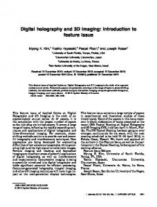
The two most widely used techniques for optical phasecontrast microscopy are the Zernicke and the Nomarski methods. These techniques are eff icient for imaging purposes but cannot be directly applied in optical metrology, when quantitative measurements are desired. Zernicke microscopy suffers from two artifacts, the so-called halo and shading-off effects,1 which make correct quantitative measurements impractical. With Nomarski microscopy, precise quantitative measurements are possible but require the use of sophisticated techniques for signal acquisition and processing.2 For applications in metrology, interference microscopy techniques3 have been developed. Most of them are based on phase-shifting inteferometry and require the recording of four interferograms for appropriate phase steps (90±) of the reference wave. In this case the drawback is that precisely controlled subwavelength translations of the sample or of a reference mirror are required. In this Letter we propose a digital holography method that uses a CCD camera for hologram recording and a numerical method for hologram reconstruction. Similar techniques have been developed for amplitudecontrast imaging4,5 and for measurement of deformations by hologram interferometry.6 Here we present a new reconstruction method that simultaneously provides an amplitude and a phase-contrast image of the specimen, on the basis of a single hologram. We also demonstrate that digital holography produces a quantitative phase contrast, meaning that the obtained phase distribution is equal, modulo 2p, to the phase distribution at the surface of the sample. This means that the obtained phase-contrast image is free of optical artifacts and can be directly used for quantitative measurements such as surface profilometry. As shown in Fig. 1, the experimental setup basically consists of a Michelson inteferometer. The beam of a He –Ne laser is enlarged to a diameter of ,20 mm by a beam expander including a spatial filter. At the exit of the interferometer a hologram is created by the interference between the object wave, Osx, yd, and the reference wave, Rsx, yd. The hologram intensity, IH sx, yd jRj2 1 jOj2 1 Rp O 1 ROp ,
(1)
is recorded by a standard black-and-white CCD camera (Hitachi Denshi KP-M2). Two neutral- density fil0146-9592/99/050291-03$15.00/0
ters allow the adjustment of the object and the reference intensities. A square image of area L 3 L 4.83 mm 3 4.83 mm containing N 3 N 512 3 512 pixels is acquired in the center of the CCD sensor, and a digital hologram is transmitted to a computer via a frame grabber that performs eight-bit digitization. The digital hologram IH sk, ld results from twodimensional spatial sampling of IH sx, yd by the CCD: ∂ x , y IH sk, ld IH sx, ydrect L L N N X X 3 dsx 2 kDx, y 2 lDyd , µ
k
(2)
l
where k and l are integers s2Ny2 # k, l # N y2d and Dx and Dy are the sampling intervals in the hologram plane; Dx Dy LyN. The numerical method that we are using for hologram reconstruction simulates the standard optical reconstruction of a hologram. In classical holography reconstruction is achieved by illumination of the hologram with a replica of the reference wave. A wave front Csx, yd Rsx, ydIH sx, yd is transmitted by the hologram and propagates toward an observation plane, where a three-dimensional image of the object can be observed. Here, as we reconstruct a digital hologram, a digital transmitted wave front CskDx, lDyd is computed by multiplication of digital hologram IH sk, ld by
Fig. 1. Experimental setup: NF’s, neutral-density filter’s; M, mirror; O, object wave; R, reference wave. Inset, detail showing the off-axis geometry at the incidence of O upon the CCD. 1999 Optical Society of America
292
OPTICS LETTERS / Vol. 24, No. 5 / March 1, 1999
a digitally computed reference wave, RD sk, ld, called the digital reference wave. Taking into account the def inition of the hologram intensity [Eq. (1)], we have
This transverse resolution is related to the size of the CCD sLd and to the distance d by4,7
CskDx, lDyd RD sk, ldIH sk, ld RD jRj 1 RD jOj 1 R Rp O 1 R ROp . (3)
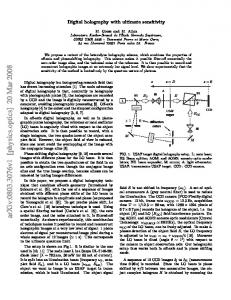
The reconstructed wave front is an array of complex numbers. The amplitude- and the phase-contrast images can be obtained by calculation of the square modulus fResCd2 1 ImsCd2 g and by the argument hatanfResCdyImsCdgj of CsmDj, nDhd, respectively. The computation time for algorithm (5) is less than 1 s with a 266-MHz G3 processor. The performance of the technique for quantitative phase-contrast imaging was tested with a pure phase object obtained by evaporation of a thin film of aluminum (thickness, >70 nm) over a surface of a resolution test target (USAF 1950). Initially, the test target consisted of a glass plate on which the USAF elements were created by chromium evaporation. After the aluminum deposition, the object appeared as a metallic mirror with step heights of a few tens of nanometers at the locations of the underlying chromium elements. An example of the results obtained with this object is shown in Fig. 2. The reconstructed images present the third element of group 0 of the USAF test target (1.26 line pairsymm). As expected for such a pure phase object, no contrast in amplitude appears [Fig. 2(a)] because the optical properties are the same over the entire surface of the sample. However, the sides of the USAF elements can be distinguished because of edge diffraction. In contrast, one can see in Fig. 2(b) that the elements are clearly revealed in the phase-contrast image. As shown in three-dimensional perspective of Fig. 2(c), this phase contrast reveals the topography of the sample. The height distribution hsj, hd on the sample surface is simply proportional to the reconstructed phase distribution fsj, hd:
2
D
2
D
The first two terms of Eq. (3) correspond to the zero order of diffraction, the third term to the twin image, and the fourth to the real image. To avoid an overlap of these three components of C during reconstruction, we recorded the hologram in the so-called off-axis geometry. For this purpose the mirror in the reference arm, M, is oriented such that the reference wave R reaches the CCD at an incidence angle u (see the inset in Fig. 1). The value of u must be suff iciently large to ensure separation between the real and the twin images in the observation plane. However, u must not exceed a given value so that the spatial frequency of the interferogram does not exceed the resolving power of the CCD.4 The images presented in Fig. 2 show not the entire area of the reconstructed images but only a selected region of interest that contains the real image. For phase-contrast imaging RD must be a digital replica of the reference wave that was used for hologram creation sRd. Indeed, as Eq. (3) shows, one can see that if RD is equal to R, the product RD Rp becomes real sRRp jRj2 d and the phase of the twin image sOd can be reconstructed. RD can also be a replica of the complex conjugate of R. In this case the phase of the real image sOp d can be reconstructed. If we assume that mirror M ref lects a plane wave of wavelength l, RD can be calculated as follows: ∑
∏ 2p skx kDx 1 ky lDyd , RD sk, ld AR exp i l
(4)
Dj Dh ldyL .
(6)
where kx and ky are the two components of the wave vector and AR is the amplitude. The computation of a digital reference wave differentiates our approach to digital holography from that of previous works.4 – 7 The digital transmitted wave front CskDx, lDyd is def ined in the hologram plane Oxy. The propagation of CskDx, lDyd is simulated by a numerical calculation of scalar diffraction in the Fresnel approximation. The reconstructed wave front CsmDj, nDhd, at a distance d from the hologram plane, in an observation plane Ojh, is computed by use of a discrete expression of the Fresnel integral4,7: ∑
∏ ip 2 2 2 2 CsmDj, nDhd A exp sm Dj 1 n Dh d ld ∑ ∏æ Ω ip 2 2 , 3 FFT RD sk, ldIH sk, ldexp sk Dx 1 l2 Dy 2 d ld m, n (5) where m and n are integers s2Ny2 # m, n # Ny2d, FFT is the fast Fourier transform operator, and A expsi2pdyldysildd. Dj and Dh are the sampling intervals in the observation plane, and they def ine the transverse resolution of the reconstructed images.
Fig. 2. Reconstructed images obtained with a pure phase object: (a) amplitude contrast, ( b) phase contrast, (c) three-dimensional perspective of the reconstructed height distribution (the vertical scale is not equal to the transverse scale).
March 1, 1999 / Vol. 24, No. 5 / OPTICS LETTERS
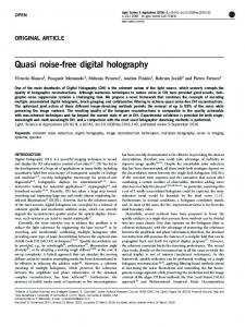
Fig. 3.
Step-height measurement.
hsj, hd sly4pdfsj, hd .
(7)
As usual with interferometric techniques, the values of the measured phase are restricted to the f2p, pg interval. Therefore, height differences greater than ly2 give rise to an indeterminancy that can be resolved by use of standard phase-unwrapping methods. As established by Eqs. (4) and (5), the numerical method for hologram reconstruction involves four parameters, AR , kx , ky , and d. To obtain well-focused reconstructed images one must ensure that the d value corresponds precisely to the distance between the object and the CCD during hologram recording. For the image presented in Fig. 2 we have d 35.1 cm. The three other parameters are related to RD [see Eq. (4)]. The adjustment of amplitude AR is not of particular importance, and its value is generally set to unity sAR 1d. The values of kx and ky require precise adjustment because these parameters define the phase of the digital reference wave. Their values must be adjusted such that the wave fronts of RD match as closely as possible the wave fronts of the complex conjugate of the reference wave R. For the images presented in Fig. 2 the values of these parameters are kx 23.12 3 1023 and ky 25.34 3 1023 . As mentioned above, the reconstructed phase distribution can be used for quantitative measurements, as is illustrated in Fig. 3 for surface prof ilometry. A phase prof ile was extracted from the data corresponding to
293
the image presented in Fig. 2(c). The measured phase values were converted to height measurements by use of Eq. (7) and recorded in the graph shown in Fig. 3. One can see that a step height of ,55 nm is measured with digital holography. For comparison, the same step height was measured by scanning of a contactstylus probe prof ilometer (Alpha-step 500) over the corresponding area of the sample. As shown in Fig. 3, the techniques are in excellent agreement. With this surface roughness a resolution better than 10 nm can be estimated for step-height measurement with digital holography. In conclusion, we have demonstrated that digital holography is a new method for simultaneous amplitude- and phase-contrast imaging. In addition, the obtained phase-contrast image provides a quantitative measurement of the optical phase distribution at the surface of the object and can be used for applications in optical metrology. The transverse resolution can be improved by addition of magnification optics to the object arm of the interferometer. This work was supported by the Swiss National Found for Scientific Research. The authors thank A. Lagos, E. Dupas, P. Lambelet, P. Poscio, Y. Emery, and O. Coquoz for technical assistance and helpful discussions. E. Cuche’s e-mail address is etienne.cuche@epf l.ch. References 1. M. Pluta, Non-Standard Techniques for Phase Contrast Microscopy, Vol. 6 of Advances in Optical and Electron Microscopy (Academic, London, 1975). 2. P. Gleyzes, A. C. Boccara, and H. Saint-Jalmes, Opt. Lett. 22, 1529 (1997). 3. See, e.g., U. Brand and W. Hillman, Precis. Eng. 17, 23 (1995), and references therein. ¨ 4. U. Schnars and W. Juptner, Appl. Opt. 33, 179 (1994). 5. E. Cuche, P. Poscio, and C. Depeursinge, Proc. SPIE 2927, 61 (1996). 6. U. Schnars, J. Opt. Soc. Am. A 11, 2011 (1994). 7. L. P. Yaroslavskii and N. S. Merzlyakov, Methods of Digital Holography (Consultants Bureau, New York, 1980), Chap. 1.