On the other hand, the main criterion for media path is to minimize latency and ... segments, time taken to establish media connections, and latency. Note that ...
Distributed Media Control for Multimedia Communications Services Eric Cheung, Michael Jackson, and Pamela Zave AT&T Labs - Research 180 Park Avenue Florham Park, NJ 07932, U.S.A. Abstract-Recent work in Distributed Feature Composition architecture has shown that a modular, compositional architecture of feature logic can lead to successful management of feature interaction. It can also promote rapid deployment of new services and third party innovation in a communication network. ECLIPSE is an implementation of DFC that focuses on Voice over IP (VoIP) and multimedia over IP. In ECLIPSE, the signaling messages traverse units of feature logic (feature boxes), but by necessity the media data have to take a separate and more direct path. This paper describes a scheme in which the feature boxes can cooperatively control the flow of media in an optimal path, while still maintaining the benefits of the DFC architecture. This scheme supports any desired media connectivity, and is independent of VoIP protocols (e.g. SIP and H.323), or the underlying media switch fabric implementation. This result is also applicable to other component architecture for communications. Comparison is made with other schemes proposed in the literature.
I.
INTRODUCTION
Distributed Feature Composition (DFC) is a modular, component-based architecture for communication services[1], and ECLIPSE[2] is an implementation of DFC in an Internet Protocol (IP) setting where signaling and multimedia travel in an IP network. DFC/ECLIPSE helps expose and manage feature interactions, contributing to coherent system behavior and allowing fine-grained service customization and innovation. It also emphasizes a clean separation of concerns between signaling and media control. This section gives a brief introduction of DFC. The need for a separation of signaling and media in an IP environment is then discussed. This in turn leads to the need for a scheme for the distributed signaling entities to control the media, which is the subject of this paper. A. Distributed Feature Composition architecture The aspects of DFC relevant to this work are presented below. [1] and [2] give a more complete treatment. 1) At the edge of a DFC network, line and trunk interface boxes connect to devices and other networks. Resource interface boxes connect to media processing resources, e.g. multimedia player, text-to-speech server, speech recognizer and so on.
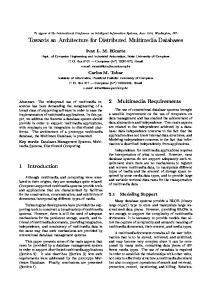
internal calls forms a usage. The ordering of the feature boxes is important, and is based on partial precedence relationship. This helps manage feature interactions. 5) DFC defines a protocol and a minimalist set of signaling messages that establish the signaling and media channels. These signaling messages travel along the usage and are processed by the feature boxes in order. 6) Logical media channels are also established along an internal call. 7) Sources and sinks of media are either in interface boxes, or in devices and resources connected to by interface boxes. Fig. 1 shows an example usage with 3 connected parties, with call waiting and hold features involved. B. Requirements for Distributed Media Control In ECLIPSE, signaling messages and media both travel over an IP network. However, they take very different paths. Signaling messages must travel through feature boxes in a usage, where these feature boxes may be distributed based on signaling efficiency and ownership criteria. On the other hand, the main criterion for media path is to minimize latency and bandwidth utilization. The media cannot travel hop-byhop through the feature boxes. Instead the media must travel in as direct a path as possible from endpoint to endpoint. Therefore, the ECLIPSE architecture is divided into a signaling layer consisting of feature boxes and interface boxes (DFC-boxes or Dboxes), and a media transport layer. The media transport layer performs the actual conveyance, switching, and mixing of media, and can be made up of one or more media switches. The Dboxes then have to be able to control the media layer. The requirements for this control mechanism are list below: Compositionality: This is a key goal of DFC, i.e. new Internal Call Media Channel
CW
HOLD
2) Units of feature logic are encapsulated in feature boxes. 3) Interface and feature boxes have ports. Two ports in 2 different boxes can be connected by an internal call.
Feature Box External Port Interface Box
Internal Port
4) An arrangement of feature boxes connected by Fig. 1. Example of a DFC usage
features can be added without modifying any of the existing features, and the new and existing features can work well together to form a better service. This requires that feature modules are autonomous and have no knowledge of other features, and there is no need for a global entity that understands the details of all the features and controls them. Efficiency and performance: Some of the considerations include bandwidth utilization overall or over specific network segments, time taken to establish media connections, and latency. Note that these can be conflicting requirements. Independence from media implementation: The feature programming in the Dboxes should be independent of the implementation details of the media switches. This also implies stability of the feature programming and changing the media implementation should not necessitate any rewrite or recompilation of the feature boxes. Distributability: there should not be any restrictions on how feature boxes and media switches can be distributed in the network. Protocol and device independence: The solution should support a wide range of devices and networks using a mixture of standard VoIP protocols, e.g. SIP[3] and H.323. We will use two example deployments to illustrate some of these requirements. The first example is an IP PBX for a business hosted in the network by a service provider. The PBX feature logic is located in the network, possibly in a multi-tenanted arrangement. However, for communications amongst workers, it is more efficient and desirable for media switches to be on premise to avoid hair pinning of media to the network. In effect the hosted IP PBX is distributed across the network and the customer premise. The second example is residential cable modems providing telephony functionality. Most broadband services offer limited upstream bandwidth. For a N-way calling feature, it is not desirable for a home device to send out multiple media streams to all the participants. Instead, it is more desirable to locate the mixing capability in the network. Although in the two cases the distribution and the variety of media switches may differs, the feature boxes should be insulated from the differences and work in both deployments without modifications. II.
MEDIA LAYER
A. Model for Media Connectivity Abstraction Based on the requirements above, we have designed an abstraction of media connectivity for Dbox programming. The abstract model is a representation of a usage, but it is more concise and only represents the media connectivity of the feature boxes that wish to control a particular medium. Because the connectivity of each medium in a multimedia communication can be different, a separate model is used for each medium. The abstract model is slave to the feature boxes. The feature boxes control and modify the specific portion of the
model that belongs to them. The model centralizes the media connectivity states distributed across the feature boxes, and its output is the aggregate of the media states of all the feature boxes. The following are the abstract entities in the model: Channels: As discussed in Section I-A, there can be multiple media channels in each DFC internal call. Each channel is characterized by the media type (voice, video, and so on) and a channel identifier. Media travel in both directions along a channel, i.e. channels are bi-directional in media connectivity. Channel terminations: For each channel, there are 2 channel terminations, one at each port of the internal call. A channel termination is identified by a (port, channelidentifier) pair. External channels and external channel terminations: An external channel is a media channel between an external port on an interface box, and an external entity such as an endpoint device or a media processing resource. An external channel is only identified by one external channel termination. Links: A link connects a channel termination to another channel termination in the same Dbox. Links are unidirectional in media connectivity. A Dbox changes its media connectivity state by controlling its links. If a channel termination receives 2 or more links, then its output is the sum of the two media streams and mixing is required. It is important that links are uni-directional. This provides flexible control of media connectivity. For example, in a contact center environment, a supervisor may wish to eavesdrop on a conversation between an agent and a customer, and whisper instructions into the agent. A ‘monitor’ feature box will then have links as shown in Fig. 2. The agent hears the caller and supervisor mixed together. B. Architecture – decomposition into three layers To maintain the model, an abstraction layer is added between the signaling and media layer to, as shown in Fig. 3. For each medium, one or more Mboxes in this layer are responsible for receiving commands from the Dboxes and maintaining a potion of the model. They in turn issue implementation specific commands to the media layer. It is important for distributability of feature logic that multiple Mboxes are supported. However, for simplicity the discussion here is limited to 1 Mbox. Having more than 1 Supervisor Link Caller
Agent Channel
Fig. 2. Links in a call center Monitor feature box
D. Model Reduction Signalling Layer control control
Mbox
Mbox Abstraction Layer
media
Media Layer
Media Switch
Fig. 3. Architecture with 3 Layers Mbox requires additional communication between the Mboxes that is media implementation specific, in a similar manner as the external channel (see below). C. Dbox – Mbox Commands A Dboxes issues a sequence of commands to its assigned Mbox to manipulate the model that the Mbox maintains. Because it only has information of its own ports and immediately neighboring ports, this scheme ensures that a Dbox can only affect its own media connectivity.
The task of the reduction engine is to reduce the abstract model of channels and links to a model consisting only of external channel terminations and how they are connected. One approach is to convert the domain specific channelslinks graph to a directed graph, and then standard graph theory algorithms (e.g. [5]) can be employed to calculate how the external channel terminations are connected. This can be performed in the following steps: 1) Replace each channel termination t with 2 vertices vin and vout. (The in and out designation refers to the media flowing into or out of a Dbox) 2) Replace each link from t1 to t2 by an edge . 3) Replace each channel between t1 and t2 by edges and . For example, to find out to where media flowing into external termination t1 should be transmitted, one can find all external terminations t where there exists a path from v1,in to vout in the directed graph.
The command set includes:
E. Media Switch Fabric Control
openLink(tfrom, tto)
Based on the connectivity of the external channel terminations, the Mbox can issue the appropriate messages to control the media implementation. In the current version of ECLIPSE we have selected H.248/Megaco[6] Media Gateway (MG) as the media switch implementation. Therefore the Mbox acts as a Megaco Media Gateway Controller (MGC), and issues Megaco commands to the MG.
closeLink(tfrom, tto) open2Links(t1, t2) close2Links(t1, t2) openChan(t1, t2) closeChan(t1, t2) openExtChan(text, remote media info) modifyExtChan(text, remote media info) closeExtChan(text)
The semantics of openLink, closeLink, openChan, closeChan and closeExtChan is self-explanatory. Open2Links and close2Links commands are shortcuts for
the very common operations of opening and closing opposing links between 2 channel terminations. For example, openLink(t1,t2) and openLink(t1,t2) can be replaced by open2Links(t1,t2). OpenExtChan(text) is used to open an external channel defined by external channel termination text, and can only be issued by an interface box. The interface box can also supply the media information of the remote side (e.g. in the form of Session Description Protocol or SDP descriptor [4]), or if it is not known at the time, supply it later with the modifyExtChan command. The Mbox replies with the media information in its media implementation. This scheme works well with protocols such as SIP as shown in Fig. 4.
When an Mbox receives a command from a Dbox, it checks the validity of the command and then updates the model. If necessary, it sends command(s) to the media switch fabric. When this is completed, the Mbox sends a reply to the Dbox to confirm success of the operation.
Another candidate for media switch fabric is the potential switching and mixing capability of SIP user agents (through the re-INVITE mechanism) and H.323 terminals (by opening and closing logical channels). However, there are some disadvantages of relying on endpoint devices for media control: 1) Commercial products have different capability. For example, some devices may be able to handle mixing of several incoming streams, or sending media to multiple destinations, while some can only handle one stream. 2) Some considerations, such as legal wiretapping and privacy, require that the source and destination of media packets to be anonymous to the endpoint devices and users. Megaco offers a general media switching and mixing solution. The media connectivity is modeled by terminations
openExtChan() Reply(SDP)
modifyExtChan(sdp)
INVITE(sdp) 200 OK(sdp)
Fig. 4. External channel commands
and contexts. Terminations are media endpoints, and are put into different contexts. By default, a termination in a context receives media from all other terminations in the same context. However, this can be modified by the mode of the terminations, and the topology of the context. Mode and topology together allow any desired media connectivity arrangement to be achieved. The external terminations in the Mbox model are mapped to terminations in the Megaco MG. To compute the context to which each termination belongs, the directed graph can be divided into its weakly-connected components. External terminations that belong to the same component also belong to the same context. Finally, the connectivity based on the paths in the directed graph can be translated into mode and topology. III.
B CF A
C CW
b a
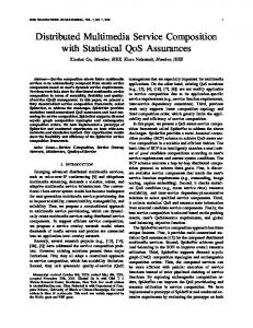
Subsequently, C activates the hold feature. HOLD issues close2Links(d,e) command to the Mbox, which recomputes the model and determines that all 3 external terminations are now unconnected. Therefore it sends a move command to the MG to move C to a new context. While this example only shows a single medium, multimedia follows naturally with one model per media stream. IV.
ANALYSIS AND RELATED WORKS
This scheme of distributed media control has been implemented in the ECLIPSE project. On top of the DboxMbox command set, we have provided a media control API for feature box programmers. We have also implemented the Mbox and the graph, model reduction and Megaco command algorithms, and a simple Megaco MG. A number of feature boxes that manipulate media have been developed, for example call waiting, call transfer and hold (mute). The use of the media abstraction has been shown to greatly simplify the feature logic of these features. How the requirements set out in Section I-B are met is discussed below:
d
e
B A context 1
C reduced model
context 2
C
(a) Initial state: A and B talking. b a
c
d
e
B
B
A
A
Fig. 5(a) shows the abstract model and the output of the reduction (lower left). A and B are connected, there the terminations representing them are in one context. C is in a separate context. Note that B subscribes to call forwarding (CF) feature, but as it does not take part in media control, it is not assigned an Mbox and does not contribute to the model. A then activates call waiting (e.g. with hook-flash). The CW sends close2Links(a,b) and open2Links(a,c) to the Mbox. From reduction of the model, the Mbox determines that A and C are connected, and B is unconnected. It then sends a Megaco move command to the Megaco MG to move A to context 2.
c
B A
EXAMPLE
An example with 3 users A, B and C is shown in Fig. 5. A subscribes to calling waiting (CW) feature, and C subscribes to a hold feature. At the beginning of the example, A is on 2 separate calls to B and C, and is using CW to put C on hold. At the same time, C’s HOLD feature has not been activated.
HOLD
context 1
C
context 2
C
(b) CW box activated to switch to C b a
c
d
e
B
B
A
A C
context 1
context 2
context 2
C
(c) C activates HOLD feature
Fig. 5. Example of media control by 2 feature boxes Compositionality: This is achieved as the Dboxes can independently issue commands to the Mbox. Distributability: The Mbox and MG are fully distributed in the network. The only limitation is that at call setup, a newly instantiated feature box is assigned an Mbox, and this assignment lasts the lifetime of the feature box (usually the duration of the call). Independence from media implementation and stability: The Mbox layer has undergone several changes while the Dbox programming was able to remain unchanged. In the event of changing the media implementation, only the Mbox needs to be modified. Efficiency and performance: It may seem that routing media through the media gateway all the time is not as efficient as direct endpoint-to-endpoint media path. In implementation however, relaying via a media switch is computationally inexpensive. In terms of latency, it adds only a few milliseconds to the latency.
However, this is an area that warrants more investigation. For example, when a party is put on hold, the media is still transmitted to the media gateway. This is not an efficient use of bandwidth. Another issue is that the Mbox is where the parallel execution of the feature boxes converges, and it is potentially a bottleneck. While the media control scheme is described in the context of DFC/ECLIPSE, it should be applicable to other distributed component architecture as well. For example, SIP suggests distribution of feature logic across endpoints (user agents or UAs) and network-based servers (proxy servers and back-toback UAs). These entities can use the same technique to control media connectivity as well. A related work in the SIP community is described in [7]. In this proposal, feature logic is contained in entities called Application Servers (AS’s). Much of this work discusses how a single feature in an AS issues SIP INVITE requests to control media. Changes to media connectivity mid-call are achieved by the AS sending re-INVITE requests, and the endpoints interpreting them correctly. This work also describes how multiple AS’s may be linked together in a chain. In this case, the AS’s must relay the re-INVITE requests correctly. For example, consider a scenario where an AS has call waiting functionality, and another AS has hold activated. When call waiting is triggered, the call waiting AS will send re-INVITE requests to each of the 3 parties in the call. The hold AS, when it receives this request, will have to modify the request. Therefore, each AS has to be on constant alert for new re-INVITE requests; and based on the content of a request and the current state of the feature logic, the AS has to modify or absorb the request. This approach is not compositional, as it requires a unit of feature logic to be aware of and rely on the behavior other units. In addition, media control of each server is not encapsulated and hidden from other servers. Furthermore, as discussed in II-E, there are problems with relying on the endpoint devices to control media. For example, not all commercial SIP devices support re-INVITE requests. A comparison can also be made with the Megaco connection model of terminations and contexts. Megaco terminations are real media endpoints that represent an RTP endpoint, TDM endpoint and so on. However, in some way our model of (internal) channels and links is analogous to virtual terminations that join contexts, and topology within a context. Therefore, if Megaco is extended to support such virtual terminations, it can also be a suitable protocol for distributed media control. V.
FUTURE WORKS
While multiple Mboxes in a usage is supported by this scheme, there are several interesting issues that arise from it. Firstly, what is the optimal assignment of Mboxes to the Dboxes? The answer will depend on the exact nature of each of the feature boxes in the usage, and this may also change in the lifetime of a usage as feature boxes change state. Another issue is that as the usage changes, media may pass through an Mbox unnecessary. For example, user A establishes a 3-way
call with B and C, and the feature boxes that belong to each user are assigned a different Mbox. Therefore, the 3-way calling feature box is assigned A’s Mbox, and is performing the mixing. If A drops out of the call and leave B and C in conversation, then media will be hair pinning through A’s Mbox. Therefore, a dynamic media optimization scheme is required to change the media path, while causing as little disruption to the ongoing communication as possible. Another area of further work is performance analysis; especially scalability with respect to number of feature boxes per usage, and the number of usages. As these increase, the complexity of the model increases. Further analysis is required to determine whether the computational load of the algorithms is linear or otherwise. An interesting area is to test the scheme with a mixed media switch implementation, for example with Megaco MG and SIP re-INVITE mechanism. This has the advantage of being able to exploit the switching and mixing capability of SIP UAs if it is provided. These devices would use a SIP Mbox. For devices that do not have this capability, they would still use the Megaco Mbox. The feature boxes do not have to be aware of this choice. To conclude, we have described a scheme for distributed and compositional media control. The abstraction of media connectivity into the channel and link model isolates signaling entities from the media implementation details. An implementation using Megaco media gateway is completed. Several future work areas have also been suggested. ACKNOWLEDGMENT We would like to thank our colleagues Greg Bond, Hal Purdy, Chris Ramming and Xiaotao Wu for their helpful comments and contribution to this work. REFERENCES [1] M. Jackson, P. Zave, Distributed feature composition: A virtual architecture for telecommunication services, IEEE Trans. on Software Engineering XXIV(10):831847, Oct 1998. [2] G. Bond et al., DFC as the Basis for ECLIPSE, an IP Communications Software Platform, Proceedings of IP Telecom Services Workshop 2000. [3] M. Handley, H. Schulzrinne, E. Schooler, J. Rosenberg, SIP: Session Initiation Protocol, IETF RFC2543, 1999. [4] M. Handley, V. Jacobson, SDP: Session Description Protocol, IETF RFC2327, 1998. [5] N. Christofides, Graph Theory: An Algorithmic Approach, Academic Press, London, 1975. [6] F. Cuervo, N. Greene, A. Rayhan, C. Huitema, B. Rosen, J. Segers, Megaco Protocol Version 1.0, IETF RFC3015, 2000. [7] J. Rosenberg, P. Mataga, H. Schulzrinne, Application Server Component Architecture for SIP, IETF Internet Draft (Work in Progress), 2001.