Yan Wang1 Assistant Professor NSF Center for e-Design, University of Central Florida, 4000 Central Florida Blvd., Orlando, FL 32816-2993 e-mail:
[email protected]
Bart O. Nnaji William Kepler Whiteford Professor Center for e-Design, University of Pittsburgh, 1048 Benedum Hall, Pittsburgh, PA 15261-2210
Document-Driven Design for Distributed CAD Services in Service-Oriented Architecture Current computer-aided design (CAD) systems only support interactive geometry generation, which is not ideal for distributed engineering services in enterprise-to-enterprise collaboration with a generic thin-client service-oriented architecture. This paper proposes a new feature-based modeling mechanism—document-driven design—to enable batch mode geometry construction for distributed CAD systems. A semantic feature model is developed to represent informative and communicative design intent. Feature semantics is explicitly captured as a trinary relation, which provides good extensibility and prevents semantics loss. Data interoperability between domains is enhanced by schema mapping and multiresolution semantics. This mechanism aims to enable asynchronous communication in distributed CAD environments with ease of design alternative evaluation and reuse, reduced human errors, and improved system throughput and utilization. 关DOI: 10.1115/1.2194911兴 Keywords: feature-based modeling, form feature, semantic model, interoperability, service-oriented architecture, collaborative design
1
Introduction
With the recent occurrence of outsourcing, collaborative product development among designers, manufacturers, suppliers, vendors, and other stakeholders is one of the keys for manufacturers to improve product quality, reduce cost, and shorten time-tomarket in today’s global competition. Collaborative design is the new design process where multidisciplinary stakeholders participate in design decision making and share product information across enterprise boundaries in an Internet-enabled distributed environment. Compared to traditional stand-alone computer-aided design 共CAD兲 systems, there are new issues that need to be resolved in collaborative CAD. For example, 共i兲
Distributed geometric model: Current data models including STEP were designed for standalone CAD systems. Distributed databases need distributed data modeling schemes to optimize data access time and storage space. 共ii兲 Consistency management and version control: Design data are modified by multiple designers. Most recent and correct version should be maintained in either centralized or distributed repository. 共iii兲 Intellectual property protection: Collaborative design requires design data to be shared by different parties. Data security is essential to build trustworthy distributed CAD systems. 共iv兲 Model compression: Domain specific design data compression can improve communication performance given limited bandwidth and storage space. Usually software systems may run in two modes: interactive mode, in which commands are entered and executed one at a time, and batch mode, in which commands are listed in a batch file sequentially and execution of the batch file finishes all commands 1 Corresponding author. Contributed by the Computer Aided Product Development 共CAPD兲 Committee of ASME for publication in the JOURNAL OF COMPUTING AND INFORMATION SCIENCE IN ENGINEERING. Manuscript received January 23, 2005; final manuscript received August 11, 2005. Guest Editors: R. Sriram, S. Szykman, D. Durham.
RDF/XML,
automatically without user interaction. The issue of batch mode geometry generation for distributed CAD is discussed in this paper. Current CAD systems only support interactive geometry generation. CAD users create a geometric model by defining features step by step. These CAD systems can become fat clients in a distributed CAD environment, in which clients perform the bulk of data processing operations locally. However, in a simple webbased environment, thin-client CAD tools mainly with visualization functions cannot perform complex editing tasks locally. The majority of data processing requests are sent to the server. Synchronous communication will become the bottleneck of the overall system performance. Thus, synchronous and interactive model generation is not ideal for a distributed CAD system in which a thin-client infrastructure is used in regular enterprise-to-enterprise collaboration. In a grid-computing environment, which is a new approach to provide virtualized infrastructure, enabling people to utilize computing resources ubiquitously as utilities, CAD systems can become service providers and are available through networks in a pay-per-use fashion, in contrast to today’s buy-and-own way. A thin-client modeling environment can reduce the cost of using CAD services. Intense human involvement is a challenge to automate the geometry creation process. Usually as the first step of design implementation—geometry creation—heavily depends on the engineers’ skills of using CAD tools. In contrast, some other design processes, such as data translation, mesh model generation, finite element analysis and simulation, and process planning, can be done in batch mode with little human intervention. Batch mode processing can increase throughput of tools and reduce the cost of service providers. It also reduces human errors and enables better design data management and knowledge reuse. Automation of the geometry creation process will enable the geometric modeling process to be easily incorporated into a distributed CAD environment such that the work load of the client and communication channel can both be reduced. It will enable an integrated automation loop of CAD, CAE 共computer-aided engineering兲, and optimization in design alternative evaluation. In this paper, we propose a new geometry generation mechanism— document-driven design 共DDD兲—for batch mode feature-based geometric modeling considering ease of communication and re-
Journal of Computing and Information Science in Engineering Copyright © 2006 by ASME
JUNE 2006, Vol. 6 / 127
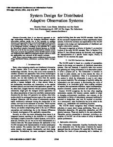
Fig. 1 Comparison between binary relation in the traditional model and a trinary relation in the semantic model: „a… Binary relations capture semantics implicitly as aggregation and association in ER-type data models, and „b… trinary relations explicitly represent semantics of constraints and design intent with good extensibility
use. Document-driven design is the design process in which a model is high level and informational. Documents give specifications and instructions for model generation. In traditional modeldriven design 共MDD兲, model is low level and normative. Model generation and evaluation are tightly coupled so that the modeling process has to be in an interactive mode. In the proposed DDD mechanism, the textual document is the only format of user input, and communication is based on that document. Document-driven process flow can simplify engineering design and analysis processes thus accelerating design cycles. Furthermore, the semantics of features is not captured actively and maintained in the existing modeling process. Interoperable feature model exchange and sharing still cannot be achieved with good scalability with existing one-to-one mapping methods. A semantic feature model is developed for the DDD mechanism in order to capture the complete requirement information and geometry specification in the document with hierarchical native engineering semantics embedding. The remainder of the paper is organized as follows. Section 2 gives an overview of related work on form feature representation and collaborative geometric modeling. Sections 3 and 4 present the semantic feature modeling scheme that allows batch mode geometry construction. Section 5 demonstrates how the document-driven design mechanism based on the semantic feature model can be applied in collaborative design.
product model data 共STEP兲 standards, the ENGEN data model 共EDM兲 关17,18兴 extended STEP’s current explicit entity representation by adding some predefined local features, such as round and chamfer in a bottom-up approach. PDES’s 共product data exchange specification’s兲 form feature information model 共FFIM兲 关19,20兴 adopted a dual representation of explicit and implicit features. Explicit features are represented generally by face lists, while implicit features are categorized into depression, protrusion, passage, deformation, transition, and area features. Some researchers used a hybrid CSG/B-Rep structure. Roy and Liu 关21兴 constructed CSG using form primitives and form features. A face-edge-type data structure is used at the low-level B-Rep. These two data structures are linked by reference faces. Wang and Ozsoy 关22兴 used primitive features and form features to build a CSG structure. Dimension and orientation information are represented as constraint nodes in a CSG tree. A face-edge-type data structure is used for lower-level entities. The connection between two structures is built by pointers from set operator nodes in CSG to B-Rep data structure and from faces to feature faces. Gomes and Teixeira 关23兴 also developed a CSG/B-Rep scheme, in which CSG represents the high-level relationships between features, and the B-Rep model describes the details. An additional feature topological structure in parallel with the B-Rep model defines volume form features.
2
2.2 Feature Semantics. Feature-based modeling is able to associate functional and engineering information with parameters and features. However, the meaning of feature cannot be consistently maintained in the modeling process. Feature semantics is domain dependent. Maintenance of semantics across domain boundaries is needed. Shah 关24兴 identified several transformation/ mapping mechanisms between application-specific feature spaces. Bronsvoort and Jansen 关25兴, Bronsvoort et al. 关26兴, and Bronsvoort and Noort 关27兴 proposed multiple-way feature conversion to support multiple feature views. Hoffmann and Joan-Arinyo 关28,29兴 developed a product master model to associate different feature views. Within the domain of form feature, feature interaction during feature construction affects the interpretation of features. Bidarra and Bronsvoort 关30,31兴 embody richer semantics by creating feature models that are independent of geometric models. Feature validity is maintained by constraints. The historyindependent feature evaluation is based on nonmanifold geometry.
Background
2.1 Form Feature Representation. There are plenty of research efforts on form feature representation 关1–4兴. In the ASU Features Testbed Modeler 关5–7兴, features are defined in terms of parameters and rules about geometric shape. Interaction between features includes spatial relationship and volume-based constructive solid geometry 共CSG兲 tree and Boolean operations. E-REP 关8–11兴 distinguishes generated features, datum features, and modifying features and regards a CAD model as being built entirely by a sequence of feature insertion, modification, and deletion description. This system-independent feature description then is translated to explicit entity representation. Several user-defined feature representation methods were proposed. Shah et al. 关12兴 presented a declarative approach using geometric entities and algebraic constraints. Middleditch and Reade 关13兴 proposed a hierarchical structure for feature composition and emphasized the construct relationship of the features. Hoffmann and Joan-Arinyo 关14兴 define user-defined features by standard feature and constraints, and attributes, procedurally. Bidarra et al. 关15兴 include validity constraints in user-defined feature specification. Wang and Nnaji 关16兴 model the intentional feature and geometric feature independently and embedded with parametric constraints. Based on the current framework of standard for the exchange of 128 / Vol. 6, JUNE 2006
2.3 Collaborative Geometric Modeling. Initial research efforts on collaborative design were mainly to support remote data access and visualization over the Internet. Reviews are available in Refs. 关32–34兴. There has also been some work on geometric modeling for collaborative design. COCADCAM 关35兴 allows distributed CAD/CAM users to work together on surface model coediting through socket interface. Collaborative solid modeling 共CSM兲 Transactions of the ASME
Fig. 2 Semantic richness is associated with information loss during data transformation
关36兴 is an environment for multiple users to edit a shared solid object over the Web synchronously through CSG models. NETFEATURE 关37,38兴 includes Web-enabled feature modeling clients, neutral feature model servers, and database managers. Agents are defined on the server side to serve clients for feature modeling by means of CORBA protocols. MUG 关39–41兴 is a multiuser environment for collaborative conceptual design and shape modeling. Users are able to exchange design semantics and modify the same geometric model synchronously. WEBSPIFF 关42,43兴 is a Web-based collaborative feature modeling system that supports interactive feature editing. Parametric representation of features is used for direct manipulation and communication. CADDAC 关44,45兴 has a three-tier architecture, and command objects are transmitted between client and database to keep the consistency of local and master models. Li et al. 关46兴 developed a client/server modeling framework based on B-Rep representation. A face-based feature differentiation method is used to support interactive feature editing. COLLFEATURE 关47兴 supports nonlock multiuser feature editing. Li et al. 关48兴 developed a neutral feature operation mapping method for collaboration of heterogeneous systems. The above research only considers traditional interactive model construction. Batch mode feature-based modeling offers several benefits, including reduced human intervention, improved performance in distributed environments, ease of design alternative evaluation and reuse, and increased system throughput and utilization. As the distribution extensiveness of design activities increases, modeling mechanisms for complex models with ease of communication become important. The proposed DDD mechanism is to support lightweight CAD geometry construction in a service-oriented architecture with thin clients. A semantic feature model is developed to represent multilevel design intent, prevent semantics loss, and enhance data interoperability.
Fig. 4 Membership schema defines properties that are associated with semantic classes
3
Semantic Feature Model
The semantic feature model intends to capture more design intent by providing an extensible modeling method to represent feature semantics. The fundamental difference between semantic modeling and traditional modeling methods is that traditional models represent relations between entities using binary relations, whereas the semantic model uses trinary relations. The traditional binary relations of ER-alike data modeling simply model most relations as aggregation, which represents “is-part-of” relationships, and association, which represents “is-related-to” relationships. In contrast, the semantic model represents relations as subject-predicate-object triples, which explicitly capture semantics in an extensible way. The difference is illustrated in Fig. 1. In Fig. 1共a兲, feature relations are captured by binary aggregation and association in an EXPRESS-G diagram. In Fig. 1共b兲, different types of arcs represent the predicates of semantic triples, explicitly. To be more precise, if E is a set of entities and R = E ⫻ E is a set of relations, the semantics of a semantic feature f can be defined as m共f兲 = 兵具s , p , o典其, where s , o 苸 E , p 苸 R. For each statement, s is the subject, p is the predicate, and o is the object. The traditional feature models with binary relations only represent a subset of semantic feature models in which m共f兲 = 兵具s , p⬘ , o典其 and p⬘ 苸 兵aggregation, association其. Semantic feature modeling needs to consider interoperability and extensibility. It needs to support dynamic schema evolution to capture new or evolving types of semantic information and be simple to use and lightweight. The model should not make assumptions about the semantics of the metadata. It needs to be
Fig. 3 Two levels of design intent, informative and communicative, need to be captured in semantic model: „a… solid model of anchor, „b… informative design intent is the abstract intention in the plan, „c… communicative design intent is the intention manisfested during the implementation, and „d… semantic model represents design intent explicitly with subject-predicateobject triples
Journal of Computing and Information Science in Engineering
JUNE 2006, Vol. 6 / 129
Fig. 5 Membership schema can be used in feature mapping between different domains: „a… definition of feature rib in SOLIDEDGE®, which supports finite thickness extension, and „b… definition of feature rib in PRO / ENGINEER®, which does not support finite thickness extension. Extra feature cut may be needed to generated the geometry of „a…
platform independent, provide interoperability between applications that manage and exchange metadata, and support wellformed relations for construction and query. Semantics is also local and context dependent. It should not be coded with special syntax in a tightly coupled way. Static models cannot keep pace as new requirements arrive. The semantic feature model includes three aspects for interoperability and extensibility. Intent representation is the basic requirement of feature modeling. Semantic relation representation is the essence of extensibility to represent the open set of engineering semantics, and semantics interpretation derives new semantic relations from existing ones to ensure semantic completeness within one domain. 3.1 Design Intent Representation. Semantic feature modeling is able to capture more semantics with extensible trinary relations so as to improve interoperability between different system domains. As illustrated in Fig. 2, traditional CAD data interoperability problem is resolved based on the neutral geometry model 共e.g., initial graphics exchange specification 共IGES兲 and STEP兲. Information loss occurs when data are translated into languages or formats that have less expressible semantics. The semantic feature model intends to capture design semantics in an extensible way.
Data interoperability is improved by modeling with richer semantics. A multilevel modeling structure also increases the transparency between feature definition and feature evaluation. There are two levels of design intent: informative and communicative. Informative design intent is the abstract intention in the plan and contains the meaning of design. Communicative design intent is manifested during the implementation and includes the meaning of designer. A semantic feature model can specify two levels of intent with properly defined feature schema. Capturing design intent requires extensible methods to represent semantics. As illustrated in Fig. 3, two levels of design intent can be captured with extensible predicates. The semantic feature model separates implicit 共or intentional兲 features from explicit 共or geometric兲 features. It is important to represent two categories of features independently so that feature specification can be both procedural and declarative. High-level informational intent is in the nature of specification, whereas lowlevel communicative intent is more related to operation. The semantic feature model for DDD intends to migrate the way of modeling features from traditional operation oriented toward specification oriented.
Fig. 6 Semantic interpretation helps to reduce ambiguity: „a… type I ambiguity of semantics – Different combinations of semantic features can generate the same geometry, and „b… type II ambiguity of semantics – Different geometry is created from the same semantic feature. Small variation of the parameter d causes topological differences in systems, such as SOLIDEDGE and PRO/ENGINEER.
130 / Vol. 6, JUNE 2006
Transactions of the ASME
Fig. 7 Interoperable semantic feature model exchange based on common compound features: „a… search common semantics of substantive compound feature, „b… search common semantics of adjective compound feature, and „c… commonly agreed compound features are used to exchange data
3.2 Semantic Relations. The semantic relation is the predicate in the semantic triple. The essence of flexibility and extensibility of the semantic feature model is the semantic relation between features, which, in turn, provides systematic approach for information retrieval. Basic semantic relations include static aggregation, generalization, association, and instantiation; hierarchical name spaces, which delineate contexts of semantics; membership relations, which express metalevel basic meanings of static associations; geometric relations that specify spatial association in Euclidean space; Boolean relations that specify the spatial occupation in Euclidean space; and temporal relations that capture the chronological dependency of feature evaluation. 3.2.1 Membership Schema. The membership schema is the semantic relation’s vocabulary description language for feature classes. The membership schema defines properties that are used to specify classes. The associated class relations of inheritance and instantiation are also defined. The membership schema diagram in Fig. 4 shows the scope of the schema definition. In each knowledge domain the domain schema is a structured template defined by a collection of semantic categories. A semantic category is a grouping of vocabulary within a language, organizing words that are interrelated and defined by each other in various ways. A semantic class is words that share common semantic properties or attributes. Membership relations are metalevel relations between features, which give rules for feature creation, categorization and division, and transformation between domains. Domain ontology of feature semantics can thus be defined based on membership relations. Examples are subcategory and identical. Feature f 1 is a subcategory of feature f 2 if and only if the semantics of f 1 infers the semantics of f 2, denoted as m共f 1兲 債 m共f 2兲. f 1 and f 2 are identical if m共f 1兲 債 m共f 2兲 and m共f 1兲 傶 m共f 2兲. However, this universal requirement usually is too rigid for domain ontology mapping. If a se-
mantic difference between m共f 1兲 and m共f 2兲 is defined as m共f 1兲 \ m共f 2兲 : = 兵具s , p , o典 兩 具s , p , o典 苸 m共f 1兲 , 具s , p , o典 苸 m共f 2兲其, and a domain-specific semantic zero ⑀ in domain D is defined such that "f 苸 D, ⑀ 債 m共f兲, features f 1 and f 2 is identical if and only if m共f 1兲 \ m共f 2兲 債 ⑀ and m共f 2兲 \ m共f 1兲 債 ⑀. Extensibility is the prerequisite for membership schema because no standard cognitive notions for particular domains exist and conceptualization of terms varies in people’s perception. The membership schema can be used in feature mapping across domains. The definitions of features are different from CAD to CAD, from CAD to CAPP, and between other systems. The mapping process can be conducted based on membership schemata. For example, the definitions of the form feature rib are different in two CAD systems, as shown in Fig. 5. Establishing mapping between two features is necessary for interoperable data exchange. In schema models, semantic mapping can be based on graph topology, special relationships, and value types. Determining the identical relation between two rib features is the process of checking the similarity or isomorphism of two schema models. Relations between ontology domains, thus, can be established. 3.2.2 Geometric Relations. Geometric relations specify the various spatial associations in Euclidean space. These relations are constraints that dynamically change the connections between feature and entities. Geometric relations specify spatial relationships in intentional features as well as in evaluated features. 3.2.3 Boolean Relations. Union, intersect, and subtract are basic Boolean operations performed during feature evaluation. A Boolean relation between features is one of the significant relations as well as one of the major problem sources in current feature-based modeling, such as naming persistency. The noncommutative property of subtract makes feature evaluation sequence dependent.
Fig. 8 Semantics simplification reduces the degrees of feature dependency: „a… feature semantics can be simplified by introducing datum features „b… examples of semantic equivalence
Journal of Computing and Information Science in Engineering
JUNE 2006, Vol. 6 / 131
Fig. 9 Membership schema expressed in RDFS syntax
3.2.4 Temporal Relations. Temporal relations explicitly specify the chronological dependency between features as informative intent, which include precede, follow, co-occur, and independent. Temporal relations capture design history and ensure causal consistency of feature evaluation. Temporal relations are needed to complement the noncommutative property of the Boolean relation subtract. 3.2.5 Compound Relations. A compound relation allows complex features to be constructed based on basic feature definitions. Complex, but more precise semantics is needed based on the fact that compound phrases are able to express delicate meanings that are not easy to infer from the meanings of its individual parts in natural languages. For example, semantics of “white collar” is not just the intersection of semantics between “white” and “collar.” New semantics in addition to the semantics from the basic elements is generated in a compound feature. Compound relations include adjective and substantive. An adjective compound is to qualify another feature and cannot exist independently, such as countersink, Philips head, and trapezoidal runner. A substantive
Fig. 10 The semantics is enriched gradually with multiresolution RDF documents
132 / Vol. 6, JUNE 2006
compound can exist independently as a complete part, such as button head rivet, helical spring lock washer, and square neck bolt. Domain-specific features can be defined with compounds, and domain semantics structure can be built based on compound relations. 3.3 Semantics Interpretation and Data Exchange. Semantics interpretation is the process of transforming a general descriptive requirement from or to a more specific system-dependent formal semantic model. Interpretation needs to manage possible oneto-many mappings. Two examples of semantics ambiguity are shown in Fig. 6. As illustrated in Fig. 6共a兲, one geometric model could be generated with different feature constructs 共type I ambiguity兲. The combination of low-level semantic features depends on user preference and construction sequence. In Fig. 6共b兲, one semantic feature can also create different geometric models with uncertain parameters caused by reference vagueness and numerical rounding errors in different systems 共type II ambiguity兲. Parameter modification of a feature could affect the features that have reference dependency on it. Different B-Rep models may be evaluated in different systems. Type I ambiguity is a planning problem, type II ambiguity is usually treated as naming persistency and model robustness problem. 3.3.1 Semantics Composition and Decomposition. A hierarchical decomposition approach can be taken to accommodate type I ambiguity. The purpose of systematic decomposition is to rationalize the design decision-making process such that arbitrary selection of semantics is avoided. Design intent needs to be captured with multiple resolutions. Based on compound relations, semantic features are constructed hierarchically. Thus, semantics can be referred to with different levels of detail. Semantics inference derives new semantics from an existing one based on axioms and rules. The feature composition process is described briefly as follows. For some adjective compound features 兵a , b , c , . . . , z其 傺 ACF and substantive compound features 兵A , B , C , . . . , Z其 傺 SCF, if two noncommunicative composition operators are defined as 丢 : ACF ⫻ ACF → ACF and 丣 : SCF ⫻ ACF → SCF, the feature composiTransactions of the ASME
Fig. 11 Feature representation and reasoning with RDF/XML documentation: „a… informational intent oriented high-level features and „b… communicative intent oriented low-level features
tion is the process in which new compound features are created with the two composition operators. Examples are A 丣 a = B and B 丣 b = C. A different way to create C is that a 丢 b = c and A 丣 c = C. Note that only one substantive compound feature is created during the composition at any time. The associated planning problem to create A is to find an X 苸 SCF and a 兵x , y , z , . . . 其 傺 ACF such that X 丣 x 丣 y 丣 z 丣 ¯ = A. This includes the selection of both features and composition sequence. Multiresolution intent capturing can be achieved by feature representation with different levels of details. Establishing common semantic features between system domains is required to build the bridge. Figure 7 illustrates the algorithm of searching common
compound features in order to exchange feature information between two CAD domains. Identical features are searched and generated from domain-specific features based on domain rules. A common substantive compound feature is found first with necessary composition operations, as in Fig. 7共a兲. Once a common substantive compound feature is established, common adjective compound features can be searched further, as in Fig. 7共b兲. As a result of the process, new compound features may be defined. These high-level and commonly agreed compound features then are used for information exchange between domains. Crossdomain semantics without domain-specific details is essential to data interoperability.
Journal of Computing and Information Science in Engineering
JUNE 2006, Vol. 6 / 133
Fig. 12 Document-centric interaction enables loosely coupled asynchronous CAD services
3.3.2 Semantics Simplification. Semantics simplification is the process of simplifying feature dependency thus reducing type II ambiguity. The depth of feature dependency trees should be minimized during the process. Based on the continuity of geometry and the principle of semantic identification 共ID兲 关49兴, stable and persistent geometric entities need to be chosen as references whenever possible. As illustrated in Fig. 8, the roots of dependency tree usually are datum planes x, y, and z. By introducing datum features, such as planes, curves, and points, as references based on datum planes x, y, and z, the maximum depth of the tree can be reduced to 2. Semantic equivalence relations allow for multiple ways of datum selection. Simplified feature semantics enables history-independent modeling for global form features 共e.g., extrusion, hole, cut, and loft兲 in which only global references are needed. In contrast, local form features 共e.g., chamfer, fillet, rib, and pattern兲 require local references to other features. The depth of dependency trees can be reduced up to 3 if local features are involved. In summary, the interpretation process extracts and reorganizes feature semantics when semantics is transformed from or to system-dependent feature models, during which traditional feature models are derived based on semantic compound feature models. The geometry-oriented deduction inevitably loses some design intent. The main task here is not preventing information loss. Instead, accuracy of the derived data models is the major challenge. Derivation rules need to be designed to reduce ambiguity and uncertainty of interpretation and provide robust results. This is also related to semantic relation definition in specific domains. With complete and multilevel feature construction information, the semantic feature model with intent and relation can be represented in single or multiple documents. Document-based design
interaction between client and server can be achieved simplythrough document processing in a distributed CAD environment.
4
Documentation of Semantic Model
Electronic document that records semantic model can be in any format. To facilitate interoperability, open standards, such as the resource description framework 共RDF兲 / extensible markup language 共XML兲 关50兴, with commonly agreed schemata are desirable, especially with the availability of low-cost parsing tools. While XML provides syntax markup, RDF enables semanticslevel markup. Based on the XML syntax, RDF is a general language for representing information on the Web. In a collaborative design environment, semantic entities and relations may be located in a distributed fashion. With the RDF/XML syntax, entities and relations can be identified and linked over the Web. Featurebased geometric modeling can become a Web-based service. 4.1 RDFS for Membership Schema. RDF schema 共RDFS兲 is RDF’s vocabulary description language used to specify domain kinds and terms. It helps to construct the structure of membership schema. The RDFS class and property system is similar to the type systems of object-oriented programing languages, such as Java. RDF differs from many such systems in that instead of defining a class in terms of the properties its instances may have, the RDFS describes properties in terms of the classes of resource to which they apply using domain and range. For example, while a classical object-oriented system might typically define a feature class Sketch with an attribute called Direction of type Vector, a Direction property has a domain of Sketch and a range of Vector in RDFS definition. With this approach, it is easy to subsequently define additional properties with a domain of Sketch or a range of
Fig. 13 Service-oriented architecture for B2B engineering services
134 / Vol. 6, JUNE 2006
Transactions of the ASME
Fig. 15
Fig. 14 FIPER process model
Vector without the need to redefine the original description of these classes. This property-centric approach enhances the extensibility of the RDF. Figure 9 shows an example of RDFS representation of the membership schema in Fig. 5共a兲.
An overview of the DDD system
4.2 RDF for Semantic Feature Model. RDF provides a generic data format that enables Web-based intelligent information modeling, which allows for interoperability of data, machine understandable semantics for metadata, uniform query for resource discovery other than traditional text search, and integrated inference for decision making. As a standard for serializing objects, RDF facilitates document-driven processes in a Web environment. In general, as design migrates from abstract specification to concrete feature construction, the semantics of design is enriched gradually with reasoning. Being an important part of design knowledge representation, the semantics of features can be modeled in documents such that it is machine processible. Rule-based inference engines can be used to automate the evolvement of semantics. As illustrated in Fig. 10, started from the fundamental requirement of a design or functional specification P0, the compound feature is decomposed step by step toward system-specific feature construct. Based on rules, an inference engine can generi from the ith ate a new RDF document with richer semantics minfer i level RDF document with semantics of m共P 兲. Then the i + 1th
Fig. 16 DDD mechanism enables lightweight model construction based on documents: „a… document flow and processing in distributed environment, „b… sketch with global references submitted by client, and „c… models generated by PRO/ENGINEER with combinations of feature documents
Journal of Computing and Information Science in Engineering
JUNE 2006, Vol. 6 / 135
Fig. 17 A crankshaft model built with the DDD mechanism: „a… client requests DDD services from FIPER WEBTOP, „b… FIPERACS and FIPER station direct DDD services to the service provider PRO/ENGINEER, „c… system-specific individual features for PRO/ENGINEER in XML documents, and „d… PRO/ENGINEER reads the 2D sketch file, and DDD driver processes feature documents in sequence automatically
level RDF document with semantics of m共Pi+1兲 is created with the i semantic difference between minfer and m共Pi兲. The original m共Pi兲 is not necessary for the system to generate geometry. Nevertheless, to retain the original design intent, it is desirable to keep the associations among different RDF documents. In practice, design reuse and data exchange are document archiving and sharing, and the compound feature decomposition is a process of document processing. As shown in the example of Fig. 11, from abstract to concrete, high-level features of the flange in a RDF document are replaced by low-level features systematically based on inference rules in separate documents, which are specified with the generic premise-conclusion rule syntax used in some standard RDF tools, such as Jena 关51兴. Rules at different levels can also be combined and the reasoning process is shortened. While semantics is enriched as the feature model goes to detailed levels, informative intent is biased or lost as the semantics is gradually expressed by communicative intent. The top-down generic semantics decomposition needs to be supplemented with a bottom-up domain feature composition process in order to accurately generate geometric model. Documents that define system-specific features can be created and archived separately. They are linked to higher level RDF documents. During the document processing, if semantic features are detailed enough to refer to system-specific features, these system-specific documents are used to create geometry. 4.3 Document-Centric Interaction Model. In a documentcentric client-server interaction model, service consumers interact with service providers using documents that are meant to be processed as complete information. Documents could be design con136 / Vol. 6, JUNE 2006
tents, operation request message, or both in common XML format. Simple object access protocol 共SOAP兲 is such a communication protocol that is particularly suitable for XMLbased messaging. As illustrated in Fig. 12, the document-centric interaction model enables asynchronous CAD services in batch mode as well as other engineering services, such as model translation, analysis, and simulation. Thin clients can send documents of semantic feature models in RDF format to a CAD server over networks. The CAD server will process the requests and generate CAD models in native or standard format. The CAD models can then be returned to clients. During the model generation, as the primary service, semantic features defined at remote repositories may be referred by the feature model from the client. Transparent to clients, new RDF resources may be allocated and used by the CAD server as secondary services. Different from current Web document links, which only provide simple references for download at the syntax level, RDF provides semantic links such that meaningful information about resources can be obtained and intelligent Web services can be built.
5
Implementation
The document-driven geometric modeling mechanism based on semantic feature model is tested within the research testbed called PEGASUS at our research center. PEGASUS is a service-oriented distributed e-design system, which is to test concepts, functions, and interoperability of research prototypes as well as commercial software for collaborative design 关52,53兴. 5.1
Service-Oriented Architecture. Service-oriented archiTransactions of the ASME
tecture 共SOA兲 is an architectural style whose goal is to achieve loose coupling among interacting software agents. A service is a unit of work done by a service provider to achieve desired functions and end results for a service consumer. SOA is widely considered to be the best practice when solving integration problems of Web services. Similarly, transparent engineering services can be achieved with the same architecture. Data interoperability and process automation are two most important principles to enable SOA. Semantic feature model for DDD intends to embrace these two principles. We use FIPER® 1.6 关54兴 as the backbone of the infrastructure for SOA. FIPER is a service-oriented distributed framework that supports federated engineering collaboration with design and analysis tools. Asynchronous communication is based on platform and language neutral message-oriented middleware 共MOM兲 protocols. WEBSPHERE APPLICATION SERVER® 5.1 and WEBSPHERE MQ® are used. As shown in Fig. 13, enterprise-to-enterprise collaboration is achieved with loosely coupled communication of SOA. Documents are used for the purposes of specification, request, storage, and presentation.
This paper presents a new feature-based modeling mechanism—document-driven design—to enable batch mode geometry construction for distributed CAD systems. This mechanism is to support loosely coupled lightweight CAD geometry generation in a service-oriented architecture with thin clients. A semantic feature model for document-driven design is developed to capture informative and communicative design intent. Feature semantics is explicitly represented as trinary relation, which provides good extensibility and prevents semantics loss. Data interoperability between domains is enhanced by schema mapping and multiresolution semantics. Semantic feature models are represented in documents with standard RDF/XML syntax such that document processing and reasoning can be easily implemented. This mechanism aims to enable asynchronous communication in distributed CAD environments with ease of design alternative evaluation and reuse, reduced human errors, and improved system throughput and utilization.
5.2 Document Processing. FIPER provides common and standard interfaces for interaction among tools as well as a process model to represent design process in conjunction with product data. Existing tools can be easily integrated in the service supply chain. At the server side, a FIPER process model is defined, which include tasks of a document processor and a CAD service provider. The FIPER process model defines functional components for a task and their execution sequence. It also defines data flow between components in the task, as shown in Fig. 14. An overview of the DDD system is shown in Fig. 15. The document processor is developed based on Jena 关51兴. Jena is an open-source RDF Java toolkit for building semantic Web applications. It provides application programing interface 共API兲 for processing RDF and RDFS, including a generic rule-based inference engine. PRO / ENGINEER® WILDFIRE 2.0 is integrated in the process model to provide CAD services as a SIMCODE component. Based on PRO/TOOLKIT® APIs, a DDD driver for PRO/ENGINEER is developed to process incoming feature documents and generate geometric models. At the client side, the process model is accessible to thin clients with the FIPER WEBTOP Web service. Service transactions can be initiated simply through Web browsers. The DDD mechanism enables batch mode geometric model construction based on documents that contain specifications. As illustrated in Fig. 16, a client submits documents of generic semantic features and two-dimensional 共2D兲 sketch as the input context alone with a FIPER process model to the server. During the FIPER model execution, the inference engine generates systemspecific semantic features as one or more documents based on the inputs of features and rules. These feature documents then are fed into the DDD driver of PRO/ENGINEER along with the sketch. Different three-dimensional 共3D兲 models can be created with combinations of feature documents. Figure 17 shows how a crankshaft model is built with the DDD mechanism. After services are published at the FIPER application control system 共ACS兲, the FIPER station can direct service requests from ACS to the service provider PRO/ENGINEER. The FIPER SIMCODE invokes PRO / ENGINEER, and the sketch document is read into PRO/ENGINEER automatically. The selection of document driven option of DDD driver will allow it to create features one by one with each feature defined in one XML document. The client can request the DDD service with a simple Web browser. The DDD mechanism supports loosely coupled and asynchronous model generation as well as lightweight design data management and access, which enables thinclient-oriented distributed CAD services. Users can control the content of documents including the FIPER process model, 2D sketch specification, semantic feature model in RDF/XML, and inference rules.
关1兴 Shah, J., 1991, “Assessment of Features Technology,” Comput.-Aided Des., 23共5兲, pp. 331–343. 关2兴 Salomons, O. W., van Houten, F. J. A. M., and Kals, H. J. J., 1993, “Review of Research in Feature Based Design,” J. Manuf. Syst., 12共2兲, pp. 113–132. 关3兴 Shah, J. J., and Mäntylä, M., 1995, Parametric and Feature-based CAD/CAM: Concepts, Techniques, Applications, Wiley, New York. 关4兴 Pratt, M. J., and Anderson, B. D., 2001, “A Shape Modeling Applications Programming Interface for the STEP Standard,” Comput.-Aided Des., 33共7兲, pp. 531–543. 关5兴 Shah, J. J., and Rogers, M. T., 1988, “Functional Requirements and Conceptual Design of the Feature-based Modeling System,” Comput.-Aided Eng. J., 5共1兲, pp. 9–15. 关6兴 Shah, J. J., and Rogers, M. T., 1988, “Expert Form Feature Modeling Shell,” Comput.-Aided Des., 20共9兲, pp. 515–524. 关7兴 Shah, J., Rogers, M., Sreevalsan, P., Hsiao, D., Matthew, A., Bhatanagar, A., Liou, B., and Miller, D., 1990, “An Overview of the ASU Features Testbed,” Proc. 1990 ASME Computers in Engineering Conference, Boston, ASME, New York, pp. 233–242. 关8兴 Hoffmann, C. M., and Juan, R., 1993, “Erep – An Editable, High-Level Representation for Geometric Design and Analysis,” P. Wilson, M. Wozny, and M. Pratt, eds., Geometric Modeling for Product Realization, North-Holland, Amsterdam, pp. 129–164. 关9兴 Chen, X., and Hoffmann, C. M., 1995, “Towards Feature Attachment,” Comput.-Aided Des., 27共9兲, pp. 695–702. 关10兴 Chen, X., and Hoffmann, C. M., 1995, “On Editability of Feature-Based Design,” Comput.-Aided Des., 27共12兲, pp. 905–914. 关11兴 Hoffmann, C. M., 1997, “EREP Project Overview,” D. Roller and P. Brunet, eds., CAD Systems Development, Springer, Berlin, pp. 32–40. 关12兴 Shah, J., Ali, A., and Rogers, M., 1994, “Investigation of Declarative Feature Modeling,” Proc. 1994 ASME Computers in Engineering Conference, Minneapolis, ASME, New York, pp. 1–11. 关13兴 Middleditch, A., and Reade, C., 1997, “A Kernel for Geometric Features,” Proc. 4th ACM Symp. on Solid Modeling & Applications, Atlanta, ACM, New York, pp. 131–140. 关14兴 Hoffmann, C. M., and Joan-Arinyo, R., 1998, “On User-Defined Features,” Comput.-Aided Des., 30共5兲, pp. 321–332. 关15兴 Bidarra, R., Idri, A., Noort, A., and Bronsvoort, W. F., 1998, “Declarative User-Defined Feature Classes,” Proc. 1998 ASME Computers in Engineering Conference, Atlanta, ASME, New York, Paper No. DETC98/CIE-5705. 关16兴 Wang, Y., and Nnaji, B. O., 2004, “UL-PML: Constraint-Enabled Distributed Design Data Model,” Int. J. Prod. Res., 42共17兲, pp. 3743–3763. 关17兴 Shih, C. H., and Anderson, B., 1997, “A Design/Constraint Model to Capture Design Intent,” Proc. 4th ACM Symp. on Solid Modeling & Applications, Atlanta, ACM, New York, pp. 255–264. 关18兴 National Institute of Standards and Technology, 1997, http://www.nist.gov/sc4/ paramet/short/engen/edm46.pdf 关19兴 National Institute of Standards and Technology, 1988, Product Data Exchange Specification: The First Working Draft, NISTIR88-4004. 关20兴 Shah, J. J., and Mathew, A., 1991, “Experimental Investigation of The STEP Form-Feature Information Model,” Comput.-Aided Des., 23共4兲, pp. 282–296. 关21兴 Roy, U., and Liu, C. R., 1988, “Feature Based Representational Scheme of a Solid Modeler for Providing Dimensioning and Tolerancing Information,” Rob. Comput.-Integr. Manufact., 4共3/4兲, pp. 335–345. 关22兴 Wang, N., and Ozsoy, M., 1991, “A Scheme to Represent Features, Dimensions, and Tolerances in Geometric Modeling,” J. Manuf. Syst., 10共3兲, pp. 233–240. 关23兴 Gomes, A. J. P., and Teixeira, J. C. G., 1991, “Form Feature Modelling in a Hybrid CSG/Brep Scheme,” Comput. Graph., 15共2兲, pp. 217–229. 关24兴 Shah, J. J., 1988, “Feature Transformations Between Application-Specific Feature Spaces,” Comput.-Aided Eng. J., 5共6兲, pp. 247–255.
6
Conclusion
References
Journal of Computing and Information Science in Engineering
JUNE 2006, Vol. 6 / 137
关25兴 Bronsvoort, W. F., and Jansen, F. W., 1993, “Feature Modelling and Conversion – Key Concepts to Concurrent Engineering,” Comput Ind., 21共1兲, pp. 61–86. 关26兴 de Kraker, K. J., Dohmen, M., and Bronsvoort, W. F., 1995, “Multiple-Way Feature Conversion to Support Concurrent Engineering,” Proc. 3rd ACM Symp. on Solid Modeling & Applications, Salt Lake City, ACM, New York, pp. 105–114. 关27兴 Bronsvoort, W. F., and Noort, A., 2004, “Multiple-View Feature Modelling for Integral Product Development,” Comput.-Aided Des., 36共10兲, pp. 929–946. 关28兴 Hoffman, C. M., and Joan-Arinyo, R., 1998, “CAD and the Product Master Model,” Comput.-Aided Des., 30共11兲, pp. 905–918. 关29兴 Hoffmann, C. M., and Joan-Arinyo, R., 2000, “Distributed Maintenance of Multiple Product Views,” Comput.-Aided Des., 32共7兲, pp. 421–431. 关30兴 Bidarra, R., and Bronsvoort, W. F., 2000, “Semantic Feature Modeling,” Comput.-Aided Des., 32共3兲, pp. 201–225. 关31兴 Bidarra, R., and Bronsvoort, W. F., 1999, “History-Independent Boundary Evaluation for Feature Modeling,” Proc. 1999 ASME Computers in Engineering Conference, Las Vegas, ASME, New York, ASME Paper No. DETC99/ CIE-9122. 关32兴 Sriram, R. D., 2002, Distributed and Integrated Collaborative Engineering Design, Sarven Publishers, Glenwood, MD. 关33兴 Yang, H., and Xue, D., 2003, “Recent Research on Developing Web-based Manufacturing Systems: A Review,” Int. J. Prod. Res., 41共15兲, pp. 3601–3629. 关34兴 Fuh, J. Y. H., and Li, W. D., 2005, “Advances in Collaborative CAD: the-stateof-the art,” Comput.-Aided Des., 37共5兲, pp. 471–481. 关35兴 Kao, Y. C., and Lin, G. C. I., 1998, “Development of a Collaborative CAD/ CAM System,” Rob. Comput.-Integr. Manufact., 14共1兲, pp. 55–68. 关36兴 Chan, S., Wong, M., and Ng, V., 1999, “Collaborative Solid Modeling on the WWW,” Proc. 14th ACM Symposium on Applied Computing, San Antonio, ACM, New York, pp. 598–602. 关37兴 Lee, J. Y., Kim, H., and Han, S. B., 1999, “Web-Enabled Feature-Based Modeling in a Distributed Design Environment,” Proc. 1999 ASME Design Engineering Technical Conferences, Las Vegas, ASME, New York, ASME Paper No. DETC99/DFM-8941. 关38兴 Lee, J. Y., Han, S. B., Kim, H., and Park, S. B., 1999, “Network-Centric Feature-Based Modeling,” Proc. 7th IEEE Pacific Conference on Computer Graphics & Applications, Seoul, IEEE, New York, pp. 280–289. 关39兴 Cera, C. D., Regli, W. C., Braude, I., Shapirstain, Y., and Foster, C. V., 2002, “A Collaborative 3D Environment for Authoring Design Semantics,” IEEE Comput. Graphics Appl., 22共3兲, pp. 42–55. 关40兴 Anthony, L., Regli, W. C., John, J. E., and Lombeyda, S. V., 2001, “An Approach to Capturing Structure, Behavior, and Function of Artifacts in Computer-Aided Design,” ASME J. Comput. Inf. Sci. Eng., 1共2兲, pp. 186– 192. 关41兴 Cera, C. D., Kim, T., Han, J. H., and Regli, W. C., 2004, “Role-Based Viewing
138 / Vol. 6, JUNE 2006
关42兴 关43兴
关44兴
关45兴 关46兴 关47兴 关48兴
关49兴 关50兴 关51兴 关52兴
关53兴 关54兴
Envelopes for Information Protection in Collaborative Modeling,” Comput.Aided Des., 36共9兲, pp. 873–886. Bidarra, R., van den Berg, E., and Bronsvoort, W. F., 2002, “A Collaborative Feature Modeling System,” ASME J. Comput. Inf. Sci. Eng., 2共3兲, pp. 192– 198. Bidarra, R., van den Berg, E., and Bronsvoort, W. F., 2004, “Direct Manipulation of Feature Models in Web-Based Collaborative Design,” Proc. 2004 ASME Design Engineering Technical Conferences & Computers and Information in Engineering Conference, Salt Lake City, ASME, New York, ASME Paper No. DETC2004–57716. Agrawal, A., Ramani, K., and Hoffmann, C., 2002, “CADDAC: Multi-Client Collaborative Shape Design System With Server-based Geometry Kernel,” Proc. 2002 ASME Design Engineering Technical Conferences & Computers and Information in Engineering Conference, Montreal, ASME, New York, ASME Paper No. DETC2002/CIE-34465. Ramani, K., Agrawal, A., Babu, M., and Hoffmann, C., 2003, “CADDAC: Multi-Client Collaborative Shape Design System With Server-based Geometry Kernel,” ASME J. Comput. Inf. Sci. Eng., 3共2兲, pp. 170–173. Li, W. D., Ong, S. K., Fuh, J. Y. H., Wong, Y. S., Lu, Y. Q., and Nee, A. Y. C., 2004, “Feature-based Design in a Distributed and Collaborative Environment,” Comput.-Aided Des., 36共9兲, pp. 775–797. Tang, M., Chou, S.-C., and Dong, J.-X., 2004, “Collaborative Virtual Environment for Feature Based Modeling,” Proc. 2004 ACM SIGGRAPH, Singapore, ACM, New York, pp. 120–126. Li, M., Gao, S., Li, J., and Yang, Y., 2004, “An Approach to Supporting Synchronized Collaborative Design Within Heterogeneous CAD Systems,” Proc. 2004 ASME Design Engineering Technical Conferences & Computers and Information in Engineering Conference, Salt Lake City, ASME, New York, ASME Paper No. DETC2004-57703. Wang, Y., and Nnaji, B. O., 2005, “Geometry-Based Semantic ID for Persistent and Interoperable Reference in Feature-Based Parametric Modeling,” Comput.-Aided Des., 37共10兲, pp. 1081–1093. World Wide Web Consortium 共W3C兲, 1999, “Resource Description Framework,” http://www.w3.org/RDF/ HP Labs, 2001, “Jena-A Semantic Web Framework for Java,” http:// jena.sourceforge.net/ Nnaji, B. O., Wang, Y., and Kim, K. Y., 2004, “Cost-Effective Product Realization - Service-Oriented Architecture for Integrated Product Life-Cycle Management,” Proc. of 7th IFAC Symposium on Cost Oriented Automation, Gatineau/Ottawa, Elsevier, Oxford. Nnaji, B. O., Wang, Y., and Kim, K. Y., 2005, “e-Design Systems,” A. Badiru, eds., The Handbook of Industrial and Information Engineering, Taylor & Francis, London. Engineous Software, 1999, “Federated Intelligent Product Environment 共FIPER兲,” http://www.engineous.com/
Transactions of the ASME