recorder for computer compatibility or provide an analog output for monitoring on an oscilloscope or strip .... indicates the proper "buzz". The SONY recorder has ...
Bulletin of the Seismological Society of America. Vol. 66, No. 3, pp. 979 985. June 1976
A PORTABLE DIGITAL SEISMIC RECORDER WITH EVENT RECORDING CAPABILITY BY WILLIAM A. PROTHERO
ABSTRACT
A portable digital recorder with event-triggering capability has been designed, and four have been constructed and field tested. The design was based on that used for over 2 years in ocean bottom seismic capsules. The outputs of as many as four seismometers are amplified, filtered, and digitized continuously at 64, 128,256, or 512 total samples per secdnd. The digital data are mixed with a time code, identification and synchronization patterns, serialized, and passed through a 512, 1024, or 1536 sample shift register which acts as a delay line. Data are then recorded on an unmodified Sony TC800B tape recorder which is turned on when a seismic event occurs. The event is triggered when the analog/digital converter output jumps above a preset threshold. Data are recovered using the same or a similar recorder for playback. A decoder provides an analog output for field interpretation or a digital output for computer compatible input. The tape recorder capacity is 1.4 million samples, or 3 hr of recording of a single channel at 128 samples per second. INTRODUCTION
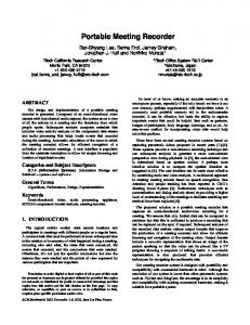
Various methods of recording seismic data in the field are in general use. Portable drum recorders, slow-running analog tape recorders, and a number of digital recording schemes (Tucker and Brune, 1974; Ambuter and Solomon, 1974) have been used successfully. Data acquired in a seismic experiment are frequently reduced to a computer compatible format by digitizing some portion of the seismic signal. Once digitized, the signal can be stored, copied, filtered, and otherwise manipulated indefinitely without additional loss of fidelity. It is desirable, therefore, to digitize the signal at the earliest possible stage of recording to avoid further loss of quality. This has the added advantage of increased dynamic range over analog recording. Amplitude compression and multiple channel recording at different gains increases the recording range, but low-level harmonic content may be lost. A high-level signal cannot be filtered for lower amplitude frequency components. This is why digital recording is superior to analog recording for studies requiring spectral analysis. Difficulties with digital recorders in the field have arisen because the data could not be easily examined on site to ensure that the system is working, not to mention the high power consumption and sheer bulk of conventional equipment. The recording equipment described in this paper solves the problem of power consumption, portability, and field checkout. Total parts cost is less than $5,000 and data playback is as convenient as with conventional analog tape recorders. The basic engineering concepts, used for 2 years in ocean-bottom recorders (Prothero, 1974), have been well-proven. Overall description. Figure 1 is a photograph of the unit in a weatherproof fiberglass case. The electronics are housed in a Vector 19-in card cage with plug-in boxes. The digital data are recorded and may be played back on the SONY TC800B recorder. Electronics are shock mounted in the case to prevent damage under the extreme vibration usually encountered during transportation to field sites. Four 12-V carbon zinc lantern batteries power the unit for up to 1 month. The weight is about 501b with batteries. The recorder can sample up to four channels of data at a total sample rate of 64, 128, 979
980
WILLIAM A. PROTHERO
256, or 512 samples per second with a 12-bit (1:4096) resolution. So, at 512 samples per second, four channels could each be sampled at 128 per second. However, if only a single channel were recorded, it could be sampled at 512 per second. Thus, the bandwidth of a single channel could be as high as 256 Hz or as low as 16 Hz (four channels at 64 samples per second). The system is meant to be operated with a remote preamplifier. Preamps have been constructed using an Analog Devices 153J operational amplifier in a sealed case with four alkaline D cells. This enables the seismometers to be placed a long distance from the recorder without the cable inductance and capacitance changing the seismometer
Fla. 1. Photograph of the digital recorder in its fiberglass case. The entire electronics m o u n t is vibration isolated from the case with Barry mounts. The tape recorder hinges upward for easy access to the batteries.
response. The amplifiers are of standard operational amplifier design with a 0.005 Hz high-pass stage and three low-pass stages that can be set to prevent aliasing at the selected sample rate. The recorder continuously digitizes the seismic signal, mixes it with a time code, adds I.D. and synchronization patterns, serializes it, and enters it into a 1536 sample delay line. An event trigger, which requires that greater than 50 per cent of the samples exceed a preset threshold for approximately 0.1 sec, turns on the tape recorder for 8 to 128 sec to record the shift register output. At 512 samples per second, approximately 2 sec of signal prior to the event is recorded. However, at 64 samples per second, as many as 23 secs prior to the trigger could be recorded. It takes approximately 1 sec for the recorder
PORTABLE DIGITAL SEISMIC RECORDER WITH EVENT RECORDING CAPABILITY
981
to reach its running speed. If additional triggers occur before the recorder is turned off, the run timer is reset to zero, so for larger earthquakes, the run time will be extended automatically. The S O N Y tape recorder is not modified. Encoded digital data are entered serially as an analog voltage. The same recorder may be used to read the data. The recorder output is connected to a rather simple decoder which can drive an incremental recorder for computer compatibility or provide an analog output for monitoring on an oscilloscope or strip chart recorder. The recorded bit density is approximately 1360 bits per second. The recorder speed can be set to 15/16ips, l~ips, 3¼ips, or 7½ips and is adjusted to result in the proper bit density. Three hours of run time at 128 samples per second is the capacity of the tape (3M 990 series). At the highest sample rate, 45 min of recording time is possible. The recording and playback system is discussed in more detail in a later section.
JAN. 26
7.2700
7
FS = 512
Trigger Signal
I
-F
t see
I
FIG. 2. Computer plot of a seismic event recorded in the Imperial Valley. The response to ground motion is 380 counts/micron at 10Hz and 240 counts'micron at 5Hz. FS is in, c o u n t s a n d the date of the recording is January 26, t975.
A binary time code replaces a data word once per second. The basic frequency is provided by a Spectrum Technology temperature-compensated crystal oscillator, which draws 5 mA at 12 V. It has less than_+ 3 x 10- 7 variation in frequency between 0°C and 50°C. The drift at constant temperature is less than 10 8 per week, which is less than 0.006 seconds perweek. However, the worst temperature variation (3 x 10- 7 error) could cause a 0.18 sec time base error in 1 week. For more accurate timing, a more precise and greater power consuming oscillator could be used. Another alternative would be to automatically digitize a WWVB time code once per day. The time counter in the recorder is set using a chronometer and check box which is carried from station to station. Thus all recorders are synchronized to the same time code. The chronometer is set using WWV. It displays the recorder time and the chronometer time so that the recorder drift can be determined. It also displays the time at which it was set to W W V so that its own drift can be determined. Other circuits in the chronometer display the digitized data and check for proper input to the tape recorder. Figure 2 shows a computer plot of an event recorded in the Imperial Valley during a field test.
982
WILLIAM A. PROTHERO
ELECTRONICS
Figure 3 is a block diagram of the system. Fairly standard low-power operational amplifiers and CMOS logic circuits are used throughout. Most of the logic wiring was done by computer-aided wire-wrap machines at EECO Corporation in Santa Ana, California. Thus, error-flee wiring was obtained. The 12-bit analog/digital converter (AD) was purchased from DATEL (ADC-CM-12B) and the multiplexer (MUX) and sample and hold circuits were designed by R. Moore and W. Prothero. The trigger circuit senses the A-D output level. When it exceeds a preset threshold, a pulse advances a counter. If more than half of the samples exceed the threshold in any 0.1sec interval, a trigger is given. Each of the four channels has a separate trigger level setting. The ocean-bottom seismic capsule has an analog trigger which requires the signal to jump eight times the time averaged ground noise to produce a trigger. However, its adjustment must be precise and is rather time consuming. A digital trigger circuit need not be trimmed, if it is working. A digital groundnoise following trigger was later developed for the ocean-bottom capsule and could be installed in this recorder in place of the existing trigger box. The 24-bit binary time code is divided into two 12-bit words and each is substituted for data once per second at evenly spaced intervals. T1 is the least significant 12 bits and T2 is the most significant 12 bits. Time is set using a portable field chronometer with zero counts defined to be midnight December 31, 1974. Then, when the data are to be analyzed, time synchronization between field recorders is straightforward. Also, time base errors can be compared between units and updated when desired using the field chronometer. The data delay shift register consists of 15 Intel P2401 dynamic shift register integrated circuits (IC's). Low power consumption is achieved by pulsing the power supply at twice the bit clock rate. The power pulses are 2 #sec wide. Data are clocked in when the power pulse is high, It is important that all incoming logic levels are low when the power is off. Data are clocked in during the 2 #sec when the power is on. The memory is divided into three banks of 512 samples each. Each bank consumes between approximately 1 and 8 mA depending on the sample rate. The first bank is on continuously and the last two are turned on when an event is triggered. This gives the tape recorder time to turn on ( ~ 1 sec), yet provides the lowest possible power consumption. DATA RECORDING
The data recording scheme deserves special discussion because even though it is used in other applications, it is somewhat unconventional. The playback logic is described in Prothero (i974). Basically, the decision to use this scheme arose from a desire for an inexpensive recorder that could be used, without extensive modification, to record field data. The SONY TC800B was chosen for its adequate tape capacity of 1800ft on a 5-in reel, its wide ranges of speed selections (15/16, 1~, 3¼and 7½ips), and its relatively vibration free operation. One would expect digital signals to be unusably distorted after passing through the frequency compensation networks used in these machines. However, with a moderately restricted bandwidth, this is not the case. Figure 4 shows a sample bi-phase data stream. The tape recorder output is typical at a density of 1360 bits per inch. Note that the data Consist simply of choices between BIT C L O C K or BIT CLOCK. The principal input frequencies are at BIT CLOCK/2 and BIT C L O C K and the harmonics of square waves at those frequencies. The first step in data decoding is to amplify and limit the signal. It is important, therefore, that spurious zero crossings do not occur. The third harmonic of data with alternating zeroes and ones (see a in Figure 4) could cause a zero
PORTABLE DIGITAL SEISMIC RECORDER WITH EVENT RECORDING CAPABILITY
:> ; r
E0
el dmos O~
U l n d unJ olno
~-~
~
8~ E
•
,
'o
o puoLumo:
~z!;!6~p
983
984
WILLIAM A. PROTHERO
crossing, as the fifth harmonic is absent. When the data bits do not change, the signal is at BIT C L O C K frequency (see b of Figure 4) and looks like a sine wave. The limitation on density at a playback speed of 256 samples per second is the high-frequency response of the recorder. Data errors comeprincipally from tape imperfections but a good tape rarely has bit errors. Entire tapes have been run error free. At a playback speed of 512 samples/second, the high-frequency response improves. With a differentiator to further enhance the high-frequency response, the density can be doubled to 2720 bits/inch. However, this causes one parity error every few seconds due to tape imperfections or recorder jitter. For most applications this would not be serious. Obviously, if one modified the tape recorder, many improvements could be made. Only half o'f the width of the tape is used. A two-track head and additional record electronics would double its capacity, but a four track head possibly could be used if the tape is good enough. A potential four to eightfold improvement thus exists. A further improvement would result if only-sine wave inputs synchronized to BIT C L O C K were used. This would eliminate the unwanted component at (3/2) BIT C L O C K and reduce its interference with frequencies at BIT CLOCK. These modifications should be made, but the engineering time was not available in the initial design.
CLOCK 7 7 _ - L - L
-2_-% CLOCK LJ-__I--__J-_ U S
DATA
7_ S__r-7 _U
O-
"7 TAP OUT rL, BI-PHASE
[--_U -1 J
F
5/
bit period
FIG. 4. A typical serial data sequence. The top three lines show the signals fiom which the Bi-phase recorder input is derived. The Tape Out signal is that observed upon playback of the data sample.
The recording system described has been remarkably reliable in the author's experience, compared with other incremental digital recorders. The tape monitor speaker readily indicates the proper "buzz". The SONY recorder has been extremely trouble-free, probably because it has been well engineered for a mass consumer market. Problems have occurred due to an occasional bad or dirty tape and due to an initial underdesign of the power switch current capacity. Otherwise, the system is simple to operate and easy to replay. RELIABILITY AND CHECKOUT
A moderately complex system such as this can become unusable if proper consideration for quick checkout and location of faults is not designed into it. However, we have found by experience with the ocean-bottom seismic capsules, that digital circuitry (particularly C/MOS) can be more easily serviced than analog and is more reliable when used by only moderately trained personnel. When digital circuitry fails, drastic equipment behavior usually ensues. Failing analog circuitry often exhibits only subtle changes, requiring greater expertise to detect. Failing C/MOS logic chips often draw excessive current
PORTABLE DIGITAL SEISMIC RECORDER WITH EVENT RECORDING CAPABILITY
985
(100 #A) and can be detected in power consumption checks. A digital system must be carefully designed and checkout procedures developed to take full advantage of these characteristics. Current consumption tests are part of each checkout. The current to each recorder subsystem may be checked easily using an ammeter built into the recorder. Every six logic IC's have a resistor in their power line to locate offenders quickly. When a new system is initially turned on, usually 5 to 10 per cent of the IC's will be unacceptable and, of the acceptable ones, 5 or 6 per cent will draw excess current during the first few days of operation. It is also important to apply the logic power slowly. An RC network of 1 ohm and 10gF is sufficient. In the absence of this, turn-on transients cause an abnormal number of IC failures. Before leaving the unit in the field, the tape recorder input is checked for proper synchronization characters using the field chronometer. In the event of a failure, special substitution boxes enable the fault to be isolated quickly. Checkout procedures have been developed to enable a person relatively unfamiliar with the details of the system to determine that it is working properly. Four recorders have been constructed and will be used first in spectral studies of earthquakes in Garm, USSR. Later, they will be used in the United States for experiments which require high signal fidelity or long unattended operation. ACKNOWLEDGMENTS Thanks are due to A. Sturman and D. Graboi for documenting, assembling, and generally making the recorders work. Also, J. King and S. Hartzetl performed critical field tests. J. King designed, assembled, and checked out the preamplifiers. This work was funded by the National Science Foundation NSF-GA-43647 as part of the joint U.S.A.-USSR cooperative project in earthquake prediction. REFERENCES Ambuter, B. and S. Solomon (1974). An event-recording system for monitoring small earthquakes, Bull. Seism. Soc. Am. 64,.1181 1188. Prothero, W. (1974). An ocean-bottom seismometer capsule, Bull. Seism. Soc. Am. 64, 1251-1262. Tucker, B. E. and J. N. Brune (1973). Seismograms, S-wave spectra and source parameters for aftershocks of the San Fernando Earthquake, San Fernando, California Earthquake of February 9, 1971, Vol. III, 69-121, Leonard M. Murphy, Coordinator, published by U.S. Department of Commerce, Washington, D.C. INSTITUTE OF GEOPHYSICS AND PLANETARYPHYSICS SCRIPPS INSTITUTE OF OCEANOGRAPHY PO BOX 1529 LA JOLLA, CALIFORNIA Manuscript received August 6, 1975