CIRED
19th International Conference on Electricity Distribution
Vienna, 21-24 May 2007 Paper 0831-
APPLICATION OF NEURAL NETWORKS TO VOLTAGE FLUCTUATIONS MEASUREMENT – PROPOSAL OF A NEW FLICKERMETER Marcin Szlosek AGH – UST Cracow – Poland
[email protected]
Zbigniew Hanzelka AGH – UST Cracow – Poland
[email protected]
ABSTRACT It can be shown, that many flickermeters do not yield credible output readings although the manufacturers declare their compliance with the requirements of standard IEC 61000-4-15. Modifications or revisions to the standard and increasing the number of requirements, what is currently taking place, seem to be interim actions, whose results are dubious. On the other hand, it should be acknowledged that since over ten years the standardization of voltage fluctuations is based on the UIE flickermeter. The authors’ idea is to treat a flickermeter – from its analogue input to the output of block 4 – as a black box, filled in by a designer accordingly to its decision, while maintaining the IN/OUT characteristics in conformity with those of the flickermeter regarded as a standard one.
INTRODUCTION Many flickermeters do not yield credible output readings although the manufacturers declare their compliance with the requirements of standard IEC 61000-4-15 [4]. Even the instruments from the same manufacturer may differ substantially in their results [1-3]. There are many proofs that provisions of this standard are not sufficiently precise. Some inexact formulations, like those regarding the definition of a modulating waveform - the depth of modulation and frequency of the modulating signal - have been rectified in the recently published annex to the standard document [4]. Similar imprecisions leave a wide margin of freedom for the instrument designer. Moreover, the standard has been prepared for flickermeters of analogue design, while most of currently available instruments are based on digital techniques. Modifications or revisions to the standard and increasing the number of requirements, what is currently taking place, seem to be interim actions, whose results are dubious. On the other hand, it should be acknowledged that since over ten years the standardization of voltage fluctuations is based on the UIE flickermeter. Thus no radical changes, like totally different method for assessment of the considered disturbance, should be introduced. The authors’ idea is to treat a flickermeter – from its analogue input to the output of block 4 – as a black box, filled in by a designer accordingly to its decision, while maintaining the IN/OUT characteristics in conformity with those of the flickermeter regarded as a standard one. For
CIRED2007 Session 2
Paper No 0831
Bogusław Świątek AGH – UST Cracow - Poland
[email protected]
this purpose a model of flickermeter was developed in MATLAB environment. In the authors’ intention it will be employed as a source of standard signals, used in further investigation. Both the reference and calibration signals according to IEC 61000-4-15, as well as the signals proposed by CIGRE JWG C4.101 were applied to the model input during repeated tests. Flicker severity Pst and Plt readings at the instrument model output were contained within permissible ranges, therefore the correct performance of the model, regarded as a standard one, was assumed proved.
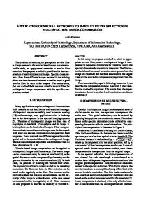
THE FLICKERMETER MODEL According to standard IEC 61000-4-15 the flickermeter design and the principle of measuring voltage fluctuations are based on human eye-brain perception, i.e. the response to the light flicker stimulus. This has lead to the conception of employing neural networks to represent the measuring part of a flickermeter. The aim of the work currently carried out is to present the conception of a neural network that performs the flickermeter tasks and to assess the effects of the network training. The assessment of the neural model correctness will be verified in a number of experimental tests to which other instruments, available on the market, were subjected. At the next stage the correctness of the flickermeter performance will be tested in an industrial experiment by means of comparing its output readings with those of other flickermeters connected at the same measurement point (e.g. at busbars of electric steelworks). The set of input and output signals, obtained from the MATLAB model in the tests already carried out, was taken as the training set for the neural network. Example waveforms of the signal applied to the flickermeter input (rectangular modulation) and the output signal at the block 4 output 5 of this instrument are presented in Fig. 1. The waveforms in Fig. 1 are related to the modulating signal with the following parameters: frequency fm=0.5[Hz] and amplitude Am=1. The designed neural network is intended to represent a flickermeter performance, except of the statistical evaluation block, i.e. the blocks 1 to 4 according to standard IEC 61000-4-15. At the further stage of this work it is foreseen to represent also the block 5, i.e. the statistical processing.
Page 1 / 4
CIRED
19th International Conference on Electricity Distribution
Vienna, 21-24 May 2007 Paper 0831-
Fig. 1 The input and output waveforms obtained from the reference model and employed to the training process
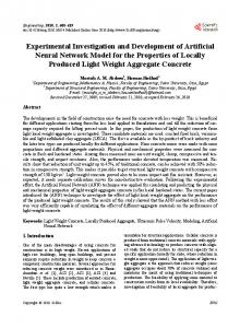
IDENTIFICATION OF THE INPUT SIGNAL ENVELOPE Assuming the flickermeter to be a black box, it was decided to divide the instrument into two parts: the signal processing block and measuring unit. The reason for this approach is that in the general case the flickermeter input signal is of random nature and character of its changes cannot be predicted. The reference waveforms given in [4] are test waveforms that can be found in actual power system. Therefore the signal expansion into Fourier series and its harmonic spectrum are taken as a one of the possible methods of the input waveform identification in the first block of the neural flickermeter. The input signal waveform is expanded into harmonic series, using the Widrow-Hoff method based on the minimum least mean square error (a.k.a. the Least Mean Squares (LMS) method). In result we obtain a waveform that represents the input signal envelope. Examples of expansion into harmonics, using the neural network, of a sinewave signal modulated by the sinusoidal waveform with parameters fm=0.5 Hz Am=0.35, and a sinewave signal modulated by the rectangular waveform with parameters fm=0.5 Hz Am=1, are presented in Fig. 2.
Fig. 2 Input signals modulated by sinusoidal and rectangular waveform (1), the estimated first harmonic of the modulated signal envelope (2)
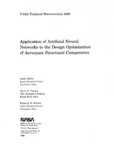
As seen from Fig. 2, the waveforms are distinctly thicker over the whole time interval (sinusoidal modulation) or only in some parts of it (rectangular modulation). It results from the applied Widrow–Hoff method of the envelope estimation. Zoomed fragments of the waveforms, indicated in Fig. 2 with dashed line, are shown in Fig. 3.
Fig. 3 Magnified fragments of the estimated envelope of input signal indicated (3) in Fig. 2
CIRED2007 Session 2
Paper No 0831
Page 2 / 4
CIRED
19th International Conference on Electricity Distribution
Vienna, 21-24 May 2007 Paper 0831-
TABLE 1: Numerical values obtained for a given number of hidden layers.
THE MEASURING UNIT OF THE NEURAL FLICKERMETER – THE SIMULATION RESULTS The results obtained form estimation of the input signal envelope can be employed to the process of training the neural network, which is responsible for the relation between the input signal (envelope) and the output signal of the flickermeter block 4 [4]. For this purpose the estimated signal of the first harmonic of the modulated signal envelope and the output signal from the block 4 (of MATLAB flickermeter model) were applied to the input of the second part of the neural network flickermeter (the measuring unit). The neural network in the measuring unit consists of three layers: an input layer, output layer and a single hidden layer. The output layer contains one neuron. The number of neurons in the input layer has initially been assumed twelve, alike the number of neurons in the hidden layer. Results of the initial phase of training of the neural network are shown in Fig. 5. The frequency of modulating signal (Fig. 5) is fm=20[Hz], and the depth of modulation is contained in the set Am={0.15; 0.199; 0.35; 0.45; 1}. As can be seen from the output signal waveform (Fig. 5), the neural network follows the reference signal. For better illustration of results the magnified portions (denoted – 2) of the graph in Fig. 5 are shown in Fig. 6. As seen in the zoomed waveforms, although the neural network output does not agree precisely with the reference signal, the trend of changes in the network signal represents the changes in the model input signal. The assumed parameter of network training accuracy, set to 10-5, has not been reached in the assumed number of 1500 iterations (training cycles). This parameter attained the value of 6.8·10-5, as compared to the assumed level 10-5. The assumed accuracy of training process has been reached after ca. 5410 iterations (the attained accuracy was 9.99·10-6), what has considerably prolonged the computations, yet at the same time improved the results of network training. The network training with accuracy of 10-6 was simulated in order to observe how the necessary number of iterations would change with the increase of the network accuracy. In this case the number of iterations in training process was 25000, although the assumed accuracy has not been reached (2.09·10-6). Thus increasing the accuracy of network training by one order of magnitude has significantly prolonged the time of training. The number of hidden layers was increased in order to investigate the neural network behaviour when changing their number. The numerical values obtained for a given number of hidden layers are tabulated in table 1. The analysis of the simulation allows ascertaining that the best results were obtained with the use of two hidden layers. This considerably fastened the training process. As compared to the network with a single layer, the use of three hidden layers yields very good results, however not as good as for two layers.
CIRED2007 Session 2
Paper No 0831
Number of hidden layers
Assumed accuracy
Obtained accuracy
Number of iterations
1
10-6
2.09·10-6
25000
2
10
-6
-7
10
-6
3
9.99·10 9.9810
-7
3410 3685
TABLE 2: CPF curves comparison for a model and neural network Model output Neural network output 1
2
3
4
5
Page 3 / 4
CIRED
19th International Conference on Electricity Distribution
Vienna, 21-24 May 2007 Paper 0831-
REFERENCES
STATISTICAL ANALYSIS OF RESULTS The next phase was estimation or statistical analysis of block III (V – according to IEC 61000-4-15 [4] standard). IEC 61000-4-15 [4] standard describes Pst ratio estimation method based on temporary flickering value p(t) obtained at block 4 output. To compare results obtained with neural meter with other flickermeters available on the market Pst indication was estimated according to the standard. Using this block to compare results obtained by different meters was necessary because of the lack of output of temporary light flickering value form the majority of classic light flickermeter constructions, except for models implemented in MATLAB environment. In table 2 and 3 exemplary results of statistical analysis of signals received at output of neural network were presented. These are the following cases presented in the following figures: 1) learning with a set of all points from table 1 [4] 2) learning with a set of all points from table 2 [4] 3) learning with individual points from table 1 [4] 4) learning with individual points from table 2 [4] 5) learning with a set of all points from table 2 [4] and table 1 [4] By analysis of relative error Pst obtained for various points, we can notice its significant value for the case in which a signal modulated by a rectangle with parameters constant over time (fm – modulating frequency, and ΔV – modulation depth) was given to the measuring system input (point 4, table 2) TABLE 3: Relative error Pst (estimating Pst based on data from the model and neural network) Pst (neural Relative error [%] Lp. Pst (model) network) 1 0,71121 0,71052 0,097 2 0,69422 0,7015 -1,049 3 0,69315 0,6906 0,368 4 0,61718 0,55172 10,606 5 0,70484 0,69812 0,953
CIRED2007 Session 2
Paper No 0831
1. Bien A., Hanzelka Z., Hartman M. et al., “Voltage fluctuations measurement – experiment in the industrial environment” Electrical Power Quality and Utilisation, 7, 2, 2001. 2. Hashad M., Hartman M., Hanzelka Z., Bien A., “The hypothesis for the wrong measurements results obtained during the flickermeter comparative test” 6th International Conf. Electrical Power Quality and Utilisation, Sept. 19-21, 2001, Cracow. 3. Piekarz M., Szlosek M., Hanzelka Z., Bien A., Stankiewicz A., Hartman M., “Comparative tests of flickermeter” 10th International Conference on Harmonics and Quality of Power, Rio de Janeiro, 6-9 October 2002. 4. IEC 61000-4-15, Flickermeter – Functional and design specifications 1997. 5. Szlosek M., Piekarz M., Hanzelka Z., Bień A., et al., “Comparative tests of flickermeters”, 17th International Conference on Electricity Distribution Barcelona 2003. 6. Korbicz J., Obuchowicz A., Uciński D., “Artificial neural networks – principles and applications” (in Polish) Akademicka Oficyna Wydawnicza PLJ, Warszawa 1994. 7. Osowski St. ”Neural networks” (in Polish) WPW, Warszawa 1996. 8. Szlosek M., Hanzelka Z., Świątek B. „Application of neural networks to voltage fluctuations measurement – a proposal for a new flickermeter” 41st CIGRE 2006 sesion, Paris France 27august – 01september 2006. This work was performed under the finance support of the Polish State Committee for Scientific Research, grant No. 3 T10A 053 30
Page 4 / 4