Ubiquitous Computing and Communication Journal
Artificial Neural Network application in Parameter Optimization of Rectangular Microstrip Patch Antenna R.Malmathanraj 1, S.Thamarai Selvi2 Lecturer /ECE National Institute of Technology, Tiruchirapalli
[email protected] 2 Professor and Head /Information Technology, Madras Institute of Technology, Anna University, Chennai.
[email protected] 1
Abstract - Printed microstrip antennas and
arrays are known to have limitations in terms of bandwidth and efficiency, all imposed by the very presence of the dielectric substrate. The paper deals with the design of a probe fed and edge fed rectangular microstrip patch antenna with the basic parameters W,h,L,εr,fo to achieve better bandwidth and directivity with efficient radiation pattern and Gain. The analytical results for various possible dimensions and different dielectric values were calculated for achieving bandwidth and directivity without any structural complexities .The analytical results were tested by simulating with basic design software PCAAD,MSTRIP40. To obtain an optimum value for the design parameters of the microstrip antenna Support Vector Machines (SVM), Generalised Regularisation Neural Network (GRNN) and Back Propagation Network (BPN) were implemented to train the network to attain optimized values to yield wide bandwidth and better directivity with high Gain. The application of artificial neural network ensures an optimum design methodology for microstrip antenna design which is revealed when comparing the results with analytical methods and the results of the simulation softwares. 1. Introduction Microstrip patch antennas have been attractive due to their conformal properties. Mathematical modeling of the basic microstrip radiator was initially carried out by the application of transmission-line analogies to
Volume 3 Number 2
Page 94
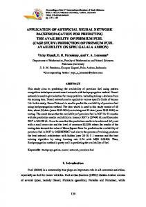
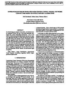
simple rectangular patch fed at the center of radiating wall. A microstrip patch antenna is a radiating patch on one side of a dielectric substrate, which has a ground plane on the underside. The EM waves fringe off the top patch into the substrate, reflecting off the ground plane and radiates out into the air. Radiation occurs mostly due to the fringing field between the patch and ground. The radiation efficiency of the patch antenna depends largely on the substrate permittivity (ε r) of the dielectric[2]. The basic geometry of the microstrip patch is shown in fig (1)
Figure 1.Microstrip Patch Antenna Geometry
Ideally, a thick dielectric is preferred for broadband purposes. Small values of width W of patch result in low antenna efficiencies www.ubicc.org
Ubiquitous Computing and Communication Journal
while large W values lead to higher order modes. Substrate thickness should be chosen as large as possible to maximize bandwidth and efficiency, but not so large as to risk surfacewave excitation. The patch length is determined by condition for resonance. This occurs when the input impedance is purely real. The bandwidth of the patch is defined as the frequency range over which it is matched with that feed line within specified limits. In other words, the frequency range over which the antenna will perform satisfactorily. This means the channels have larger usable frequency range and thus results in increased transmission. The bandwidth of an antenna is usually defined by the acceptable standing wave ratio (SWR) value over the concerned frequency range[3,4]. Dimensions of the top patch were calculated to get the required bandwidth and the impedance matching. The advantages of microstrip antenna is that they are low-cost, conformable, lightweight and low profile, while both linear and circular polarization easily achieved. Disadvantages of microstrip antenna include such as a narrow bandwidth, a low gain (~6 dB) and polarization purity is hard to achieve. Several methods were reported in literature to improve impedance bandwidth including employing wide band impedance matching, stacked patches and utilizing thicker substrates[9].
various complex structures adopted for the enhancement of bandwidth, Directivity and Gain. The size of the probe is selected as 0.2 mm and the various feeding positions were considered for the calculation[5]. The dimensions of the patch antenna along with the substrate permittivity and the probe position is varied for different operating frequencies and the numerical results were arrived using the basic design formulas of the microstrip patch listed below, The width of the Microstrip patch antenna is given by c -(1) (ε r +1) 2 f0 2 Effective dielectric constant is given by W=
−
ε reff
Effective length ( Leff ) is given by Leff =
Volume 3 Number 2
Page 95
C 2 f 0 ε reff
-(3)
Length extension ( ∆L ) is given by
∆L = 0.412h 2.Design Methodology 2.1 Basic Rectangular Microstrip The major design task of this paper is optimization of the dimensions of the probe fed rectangular microstrip patch antenna. The simplest approach is adopted to demonstrate how effectively the Artificial neural network can be used to train and optimize the various parameters involved in the design of microstrip patch antenna. This work concentrates only on the basic geometry of the microstrip ignoring
1
h 2 ε + 1 ε r −1 + -(2) = r 1 12 + 2 2 W
(ε
reff
(ε
reff
W + 0.3) + 0.264 h -(4) W − 0.258) + 0.8 h
Actual length of patch ( L ) is given by L= Leff − 2∆L
-(5)
Ground plane dimensions ( Lg and W g) is given by Lg = 6h +L -(6)
www.ubicc.org
Ubiquitous Computing and Communication Journal
Wg = 6h + W
-(7)
2.2 Artificial Neural Network Design for Rectangular Microstrip Patch Antenna . A microstrip rectangular patch antenna (Fig. 1) can be viewed as a matrix with X variables and four unknown the bs, such that
Height of the substrate is given by h≤
0.3C 2πf o εr
-(8)
The bandwidth of a rectangular patch is given by
(
)
BW = 3.77 (ε r −1) / ε 2 W / L h / λ0 ) --(9) r
(
)(
Where f 0 is the resonant frequency, ε r is the relative substrate permittivity, C is the speed of light 3 × 10⁸ m/s.
AX=b The unknown are the resonant frequency (RF), bandwidth (BW), gain(G), and polarization (PL). The variables X, are the patch length (L1), patch width(L2), substrate height (H 1) , substrate relative permittivity (ξr) and the feeding positions(Xf ) and (Yf )
[A][ L1 , L2 , ξr, H1 , X,Y, Xf Yf ]T=[G,BW,S 11,PL]T G=f(L1 , L2 , ξr, H1 , X,Y, Xf , Yf); BW=f(L1 , L2 , ξr, H1 , X,Y, Xf , Yf ); S11=f(L1 , L2 , ξr, H1 , X,Y, Xf , Yf); PL=f(L1 , L2 , ξr, H1 , X,Y, Xf , Yf ); In the neural network design the inputs are L1 , L2 , ξr, H1 , X,Y, Xf , Yf and the output is 11 G,BW,S ,PL. An artificial neural network is an information processing paradigm. That is inspired by the way biological nervous systems, such as the brain, process information. The key element of this paradigm is the novel structure of the information processing system .It is composed of a large number of highly interconnected processing elements (neurons), working in union to solve specific problems. Artificial neural network is like a normal human, it learns by examples.[2,6] A neural network with feedback is an adequate representation of the information Volume 3 Number 2
Page 96
processing structure of rectangular microstrip antennas, where the input neuron units are (L ,W, εr ,h ,P ,fo )and the output units are (BW ,D ,G ,RP ). The learning paradigm on the microstrip is supervised learning, where the mapping function between the inputs and outputs is the matrix A. The inputs are weighted and the effect that each input has at decision making is dependent on the weight of the particular input. The weight of an input is a number that when multiplied with the input gives the weighted input. Their calculation is based on the method of moments. These weighted inputs then generate the unknowns. Those unknowns are then compared to stored information that gives the desired bandwidth, directivity along with radiation pattern and gain. The gain is expected to be greater than 3 db and polarization should be linear or circular [1,2]. A good paradigm of supervised learning that is of interest to microstrip antenna designer is error correcting learning that is minimization of error between the desired and computed values. In this learning paradigm, the set of weights that minimizes the error between the teaching input and the
www.ubicc.org
Ubiquitous Computing and Communication Journal
weighted inputs is obtained. Neural networks are general function approximators. One important characteristic is that they can learn any Input-Output (IO) mapping by using the information contained in a given input-output data set without needing a structure definition of the IO-mapping. The type of network, parameter settings, number of hidden neurons, and the connectivity of the neural network define the structure of the approximated IOmapping. The only additional information a neural network needs, besides the input-output data, is the definition of the input and output parameters, the relevant parameters which span the IO-mapping. The ideal use of neural networks is antenna model parameters optimization. Without knowing the IOmapping structure of the model, the neural network can learn to mimic the IO-mapping [7,8]. In the IO-mapping problem a feedforward neural network is used because the antenna model is a static mapping (except at the very moment the design failure occurs). Also the ’tangent sigmoidal’, e.g. ’tansig’, activation function will be used in the hidden layer of the network because of two reasons. One, in the antenna design, IO-mapping is a smooth mapping with little to none discontinuities. The ’tansig’ is also a smooth function with the capability of approximating a discontinuity (by squashing the shape with respect to the input axis). The second reason for choosing the ’tansig’ function is that this function is a very ’general’ function. After a failure, the antenna design IO-mapping has changed into an unknown form. Therefore an activation function, which can be used to mimic almost all shapes, is more preferable since in that case all (unknown) IO-mapping can be approximated by the neural network. Neural networks are based on the human brain and its enormous capability of learning and adapting. Over decades, people have been trying to model the human brain
Volume 3 Number 2
Page 97
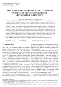
mathematically. The structure of the human brain and the learning process is known, but the main difference between both networks is the effciency. The human brain is capable of recognizing a familiar face in approximately 100-200 ms, where conventional computers can take hours or days to fulfill less complex tasks. The biological neural network is still much faster then the artificial neural network (ANN or NN), but the capabilities of the neural networks are promising. In this section, the general structure of a neural network will be explained. First the concept of neurons is treated with a special attention to the several activation functions. The possible combinations of several neurons in layers is handled in the discussion about the architecture of networks. Some example networks are used to illustrate the effect of the parameters of the networks. The primary element in a neural network is the neuron, an information-processing unit. A mathematical model of an artificial neuron in given in Fig. (2). The structure is similar to the human neuron; more information about the functioning of the human neural network. The elements xi on the left side are the input signals to the neuron k. These inputs are multiplied by the corresponding weights wki and summed together with the bias bk. The results of the summation vk is passed through an activation function ϕ (vk) producing the output yk. The mathematics of the neuron given in Fig. (2) can start with the weighted inputs p -(10) v k = ∑ wki x i i=1 The output can be written as
yk =ϕ k (vk + bk )
-(11)
A weighted bias can be included by adding an extra term in the first equation. p v = ∑ wx k i i ki =0
-(12)
www.ubicc.org
Ubiquitous Computing and Communication Journal
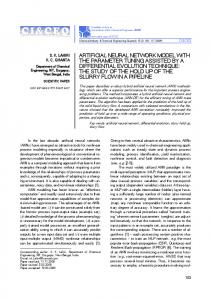
Where the bias is changed to a fixed input of 1 and with a weight of wk0 . The shape of the output is then only depending on the activation function of vk. -(13) y k = ϕ k (v k ) The type of activation function has a large influence on the output of the neuron as can be seen from the equation (12). In a signal flow diagram, a neuron can be represented as shown in Fig. (3).
x0=1 x1
wk,0 wk,1 x2
wk,2
vk ψ(k)
yk
. . . xn
wk,n
Figure 2. Mathematical definition of a neural network
X1
wk,
wk, X2 Volume 3 Number 2
Page 98
www.ubicc.org
bk
Σ
Ubiquitous Computing and Communication Journal
. . X
Volume 3 Number 2
Page 99
w
www.ubicc.org
Ubiquitous Computing and Communication Journal
Fig 3. neuron
Signal
flow
diagram
of
A neural network is a directed graph consisting of nodes with interconnecting synaptic and activation links, and is characterized by four properties: 1. Each neuron is represented by a set of linear synaptic links, an externally applied bias, and a possibly nonlinear activation link. The bias is represented by a synaptic link connected to an input fixed at +1. 2. The synaptic links of a neuron weight their respective input signals. 3. The weighted sum of the input signals defines the induced local field of the neuron in question. 4. The activation link squashes the induced local field of the neuron to produce an output. 3. Architecture Selection A variety of Neural network architectures are available to process the data from the input data set files. A multi layer Backpropagation Network architecture, Generalized Regularization neural network (GRNN) and Support vector machines (SVM) were used for training because of its ability to generalize well when applied to a wide variety of applications and also for the ability to have better regression.
Volume 3 Number 2
Page 100
a
3.1 Learning
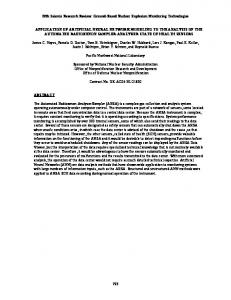
As the neural network software read the training set, the network learns the data patterns in the training set. Learning subprograms differ depending on the architecture selected. As training progressed, statistical graphs furnished by the neural net software, provided a means to monitor training progress. Numerical historical data and repetitive examples in which the solution is already known are required to train a neural network. While the relationship between variables may not be known, network results can be improved by the addition of more variables. Data may need different representation, for example if data has a very large value range, logarithms or other data transformations or conversions may be necessary. 3.2 Generalised Regularisation Neural Network (GRNN) The GRNN is based on the Nadaraya – Watson Kernel regression. GRNN’s feature fast training times can model non linear functions and have been shown to perform well in noisy environments given enough data. The primary advantage of the GRNN is the speed at which the network can be trained. Training a GRNN is performed in one pass of the training data through the network, the
www.ubicc.org
Ubiquitous Computing and Communication Journal
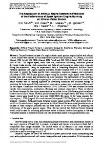
training data values are copied to become the weight vectors between layers. The architecture of the GRNN is shown in the figure 4, it has four layers input pattern, summation and output, with weighted connections Wij between the input and pattern layer and
Summation Layer
Pattern Units
Output Units
Input S S D
fo S L
S
W
BW εr
D
S- Summation Unit D- Division Unit
P
fo Figure 4.Architecture of GRNN Network
Input
Volume 3 Number 2
Page 101
www.ubicc.org
Ubiquitous Computing and Communication Journal
sets or between H1 and H2 we need to minimize ||w|| with the condition that there are no data points between H1 and H2 3.3 Support Vector Machines Traditionally neural networks have been used for classification, which is based on Empirical Risk Minimization (ERM). SVM was developed by Vapnik and had become popular tools for data mining. The formulation embodies the Structural Risk Minimization (SRM), which is superior to empirical risk minimization. SRM minimizes the upper bound on expected risk as supposed to ERM that minimizes the error on training data. So, SVM generalizes much better. There are many linear classifiers that can separate data, but SVM only maximizes the margin i.e. the distance between it and the nearest data point in each class. We have N training data {(x 1,y1), (x2,y2),….. (xN,yN)} Where xi Є Rd and yi Є {+1,-1}. It needs to be classified using a linear hyper plane classifier f(x) =sgn (w.x - b)
-(17) -(18)
Combining the above two equations, yi ( w . x – b ) >= 1
-(19)
So the problem of maximizing the distance between hyper plane H1 and H2 is formulated as min ½ wT w subject to yi ( w . x – b ) ≥ 1
-(20)
This is a convex quadratic problem in w, b in a convex set. The solution is found by solving using lagrangian method by introducing lagrangian multipliers. It is easier to solve using lagrangian dual equation given by LD = Σi αi - Σi Σj αi αj yi yj xi · xj
-(21)
-(14)
This hyper plane will have maximum distance between each class. This hyper plane H : y =w . x – b = 0 and two hyper planes parallel to it H1 : y =w . x – b= +1
-(15)
H2 : y =w . x – b = -1
-(16)
With no data points between H1 and H2, and distance between H1 and H2 maximized. Some training point will lie on the hyper plane H1 and H2, they are called support vector machines because they define the separating plane and the other training points can be removed or moved provided they don’t cross the planes H1 and H2. The distance between hyper plane H1 and H2 is 2/ || w||. To maximize the distance between the two data
Volume 3 Number 2
w . x –b ≥ +1 for yi = +1 w . x –b ≤ -1 for yi = -1
Page 102
The significance of the above equation is that the training input vectors appear only as dot product. So when the data is not linearly separable it is required to transform the data into a higher dimensional. This causes complex calculations in neural networks but in SVM as data appear only as a dot product all calculation can be carried explicitly in low dimension if a kernel function exists for LD = Σi α i - Σi Σj α i αj yi yj Φ(xi) · Φ(xj) -(22) as Φ(xi ) · Φ(xj ) = K(xi , xj ) Where K is the kernel function. This is equivalent as the dot product in high dimension is equal to kernel function in input space. The common kernel function used is Gaussian kernel, K (xi , xj) = e - || xi – xj || 2 / σ 2
-(23)
www.ubicc.org
Ubiquitous Computing and Communication Journal
Mercers condition determines whether a function g(x) can be used as a kernel or not, 2 ∫ g(x) dx should be finite. 4.Design Implementation and Result. The dimensions of the rectangular patch were selected in a trial and error basis considering the constraints of the design in selecting the values. The different geometrical parameters were designed analytically and the bandwidth given in equation (9) was used to calculate the value for the selected dimensions. The parameters were used to construct the structure using the simulation software. The bandwidth and directivity along with the gain and radiation pattern of the design were obtained. The parameters of the patch equations (1-9) with the feed position for a resonant frequency are fed as input to the networks. The impedance bandwidth and directivity was taken as the output of the network. The analytical data values are given as input to train the network to obtain an optimized geometry for the probe fed microstrip antenna .The wide range of parameters was used to provide the optimum result and the training steps were increased to obtain the accuracy. The validity of the network was tested by comparing the analytical results obtained from the basic formulas for a given set of input values. The same parameters were used to construct a probe fed rectangular patch using simulation software shown in figure (7) and the output radiation pattern was obtained as shown in figure (8). The current pattern of the designed antenna is also plotted which shows the even distribution due to proper impedance matching of the probe feed. The same values were trained using the three networks Backpropagation Network architecture (BPN), Generalized Regularization neural network
Volume 3 Number 2
Page 103
(GRNN) and Support vector machines (SVM) whose results were in good agreement with the analytical as well as the designed structure output shown in Table (1). The input output relations were also checked for the experimental results. The Backpropagation Network architecture achieves the antenna parameter optimization with maximum time for convergence. The GRNN and the SVM neural network achieves optimization with quicker learning time as shown in Fig 11 and 12. In this research analysis for antenna parameter optimization the GRNN neural network produced the accurate result with comparatively minimum time for convergence. The computational time was very less in terms of seconds with high accuracy as shown in Fig 13. The optimized parameters obtained using the training neural networks achieved high impedance bandwidth of 7.8%, directivity 7.73db without side lobes and offered high gain 8.67 dbi and radiation efficiency 100% was attained. The results were comparatively better when compared with the results from analytical analysis and simulation analysis for Microstrip patch antenna using PCAAD and MSTRIP40. To train the SVM parameters [alpha,b] = trainlssvm ({X, Y, type, gam, sig2, kernel, preprocess})
Outputs alpha matrix with support values of SVM b
vector with bias term(s) of SVM
Inputs
www.ubicc.org
Ubiquitous Computing and Communication Journal
Fig 5. Antenna output model using MATLAB Software .
Fig 6 Antenna output model using MATLAB Software .
Volume 3 Number 2
Page 104
www.ubicc.org
Ubiquitous Computing and Communication Journal
Model Trained object oriented representation
Gam
Regularization parameter
of the SVM model
sig2
Kernel parameter (bandwidth in the
Model Object oriented representation of the
case of the 'RBF_kernel')
SVM model
kernel Kernel type default 'RBF_kernel'
X
matrix with the inputs of the
training data Y
Xt
inputs of the test data
preprocess
preprocess
vector with the outputs of the
training data
Plotting the graph in SVM
Type function estimation
plotlssvm({X,Y,type,gam,sig2,'RBF_kernel','p
Gam
Regularization parameter
reprocess'},{alpha,b});
sig2
Kernel parameter (bandwidth in the
case of the 'RBF_kernel')
Inputs X
kernel Kernel type (by default 'RBF_kernel')
data
preprocess
Y
preprocess'(*) or 'original'
matrix with the inputs of the training
vector with the outputs of the training
data Simulating the SVM
Type function estimation
Yt=simlssvm({X,Y,type,gam,sig2,'RBF_kerne
Gam Regularization parameter
l','preprocess'},Xt);
sig2
Kernel parameter (bandwidth in
the case of the 'RBF_kernel') Outputs
kernel
Yt
'RBF_kernel')
matrix with predicted output of test
data
Inputs X
type
(by
default
preprocess
preprocess
alpha
support values obtained from
training matrix with the inputs of the training
data Y
Kernel
b
Bias
term
obtained
from
training vector with the outputs of the training
data Type function estimation
Volume 3 Number 2
Page 105
5.Conclusion The radiation pattern of the designed antenna presented in this paper figure (7) clearly depicted that it is a wideband antenna with high directivity, gain with radiation www.ubicc.org
Ubiquitous Computing and Communication Journal
efficiency. The major attraction of this antenna is size reduction along with bandwidth and directivity made it most suitable for satellite communication, commercial applications. The size reduction and operating frequency make it suitable
Figure 7.Structure of Probe Fed Microstrip Rectangular Patch Antenna
for mobile communication. The parameter optimization using the networks is the major attraction of this paper, which highlights the simplicity, accuracy and reduction in computational time for the designers of interest.
Figure 8.Current Distribution
Figure 9. Radiation Pattern of the Optimized Patch Antenna Figure 10. Plot Showing the Learning Trial of Back Propagation Network
Fig 1 1. Plot to show the time for convergence for SVM neural network.
Volume 3 Number 2
Page 106
www.ubicc.org
Ubiquitous Computing and Communication Journal
Fig 13. Plot to show the weight surface of SVM Fig 1 2. Plot to show the time for convergence for GRNN neural network.
Figure 15. Output of the Optimized output of the rectangular patch antenna using MSTRIP
Volume 3 Number 2
Page 107
Fig 14. Plot to show the radiation pattern using PCAAD
www.ubicc.org
Ubiquitous Computing and Communication Journal
References 1.Dipak K.Neog, Shyam S.Pattnaik, C.Panda, Swapna Devi, Bonomali Khuntia, and Malaya Dutta, “Design of a Wideband Microstrip Antenna and the use of Artificial Neural Networks in Parameter Calculation”, IEEE Antennas and Propagation Magazine, Vol.47, No.3, June 2005,pp.60-65. 2. Inder J.Bahl, Prakash Bhartla and Stanislaw S. Stuchly, “ Design of Microstrip Antennas Covered with a Dielectric Layer”, IEEE Transactions on Antennas and Propagation, Vol. AP -30, No. 2, MARCH 1982, pp. 314-318. 3. Kin-Lu Wong and Yi-Fang Lin, “Small broadband rectangular microstrip antenna with chip-resistor loading”, ELECTRONICS LETTERS, 1 l September 1997, Vol. 33 No. 79,pp.1593, 1594. 4. S.Lebbar, Z.Guennoun, M.Drissi, and F.Riouch, “A Compact and Broadband Antenna Design Using a Geometrical- MethodologyBased Artificial Neural Network”, IEEE Antennas and Propagation Magazine, Vol.48, No.2, April 2006,pp.146-154. 5. C. L. Mak, K. M. Luk, Senior Member, IEEE, K. F. Lee, Fellow, IEEE, and Y. L. Chow, “Experimental Study of a Microstrip Patch Antenna with an L-Shaped Probe,” IEEE Transactions on Antennas and Propagation, VOL. 48, NO. 5, MAY 2000,pp.777-783. 6. R.K.Mishra and Patnaik, “Designing Rectangular Patch Antenna Using the Neurospectral Method”, IEEE Transactions on Antennas and Propagation,AP-51,8 August 2003,pp.1914-1921. 7. S.S.Pattnaik, D.C.Panda and S.Devi, “Input Impedance of Rectangular Microstrip Patch Antenna Using Artificial Neural Networks”, Microwave and Optical Technology Letters,32,5,5 March 2002,pp.381-383. 8. S.S.Pattnaik, D.C.Panda and S.Devi, “Radiation Resistance of Coax-Fed Rectangular Microstrip Patch Antenna Using Artificial Neural Networks”, Microwave and Optical Technology Letters, 34,1,5 July 2002,pp.51-53. 9. D.M.Pozar, “Microstrip Patch Antennas,” in L.C.Godara (ed), Handbook of Antennas in Wireless Communications, New York, CRC Press, 2001,Chapter 6. 10.Ye Bin Hu Gu Yu , “The analyze and improve TCP performance using a DSR route protocol based on signal strength”, IEEE Wireless Communications, Networking and Mobile Computing, pp. 846 – 849, 2005. 11. Dongkyun Kim , Hanseok Bae, Jeomki Song, “Analysis of the interaction between TCP variants and routing protocols in MANETs”, IEEE Parallel Processing, ICPP 2005 Workshops, pp 380-386, 2005. 12. Prabakaran, M. Mahasenan, A. , “Analysis and enhancement of TCP performance over an IEEE 802.11 multi-hop wireless network: single session case”, IEEE International Conference on Personal Wireless Communications, pp-29- 33, 2005 13. Caihong Kai Yuzhong Chen Nenghai Yu, “An Improvement Scheme Applied to TCP Protocol in Mobile Ad Hoc Networks”, IEEE International Conference on Mobile Technology, Applications and Systems, pp.1-6, 2005
Volume 3 Number 2
Page 108
www.ubicc.org