SUST Journal of Engineering and Computer Science (JECS), Vol. 15, No. 2, 2014
Control of Induction Motor Drive using Artificial Neural Network Taifour Ali1, Abdelaziz Y. M. Abbas2, Ekram Hassabo Abaid Osman3 1,2
School of Electrical & Nuclear Engineering, Sudan University of Science & Technology, Sudan 3 Dept. of Electrical Engineering Technical College PortSudan
[email protected]
Received:01.03.2013 Accepted:11.04.2013 ABSTRACT - The induction motor drive is a dynamic nonlinear system with uncertainty in the machine parameters. The aim of this study is to improve tracking performance of the induction motor drive. A method for controlling induction motor drive is presented with conventional Proportional-Integral (PI) controller and Artificial Neural Networks (ANNs) controller. MATLAB/SIMULINK software is used to develop a three phase induction motor model. Also the performances of the two controllers have been verified. The ANN is trained so that the speed of the drive tracks the reference speed. It is found that with the use of the ANN controller the performance and dynamics of the induction motor are enhanced as compared with that of a conventional PI controller. Keywords: Artificial Neural Networks, Control, P.W.M (Pulse Width Modulation), Back propagation, vector control
. ﻫدف ﻫذﻩ اﻝدراﺴﺔ ﻫو ﺘﺤﺴﻴن أداء اﻝﺘﺘﺒﻊ ﻝﻠﻤﺤرك اﻝﺤﺜﻲ. اﻝﻤﺤرك اﻝﺤﺜﻲ ﻋﺒﺎرة ﻋن ﻨظﺎم دﻴﻨﺎﻤﻴﻜﻲ ﻻ ﺨطﻲ ﺒﺜواﺒت ﻏﻴر ﻤؤﻜدة- اﻝﻤﺴﺘﺨﻠص أﺴﺘﺨدم اﻝﺒرﻨﺎﻤﺞ.طرﻴﻘﺔ اﻝﺘﺤﻜم ﻓﻲ اﻝﻤﺤرك اﻝﺤﺜﻲ ﺘم ﺘوﻀﻴﺤﻬﺎ ﺒﺎﻝﻤﺘﺤﻜم اﻝﺘﻘﻠﻴدي اﻝﺘﻨﺎﺴﺒﻲ اﻝﺘﻜﺎﻤﻠﻲ و اﻝﻤﺘﺤﻜم اﻝﺸﺒﻜﻲ اﻝﻌﺼﺒﻲ اﻻﺼطﻨﺎﻋﻲ درﺒت اﻝﺸﺒﻜﺔ اﻝﻌﺼﺒﻴﺔ اﻷﺼطﻨﺎﻋﻴﺔ. و ﺘم اﻝﺘﺤﻘق ﻤن أداء اﻝﻤﺘﺤﻜﻤﻴن. ﻝﺒﻨﺎء ﻨﻤوذج ﻝﻠﻤﺤرك اﻝﺤﺜﻲ ﺜﻼﺜﻲ اﻝطورMATLAB/SIMULINK ﻝﻘد وﺠد أن ﺒﺎﺴﺘﺨدام اﻝﻤﺘﺤﻜم اﻝﺸﺒﻜﻲ اﻝﻌﺼﺒﻲ اﻷﺼطﻨﺎﻋﻲ ﻴﻜون اﻷداء اﻝدﻴﻨﺎﻤﻴﻜﻲ ﻝﻠﻤﺤرك.ﺤﺘﻰ ﺘﺘﺒﻌت ﺴرﻋﺔ اﻝﻤﺤرك اﻝﺴرﻋﺔ اﻝﻤرﺠﻌﻴﺔ .اﻝﺤﺜﻲ ﻗد ﺘﺤﺴن ﻤﻘﺎرﻨﺔ ﺒﺎﻝﻤﺘﺤﻜم اﻝﺘﻘﻠﻴدي اﻝﺘﻨﺎﺴﺒﻲ اﻝﺘﻜﺎﻤﻠﻲ
Recently, many techniques have been developed for induction motor drives and hence very good control performances have been achieved. Among the existing techniques, the most commonly used one is the Proportional-Integral (PI) controller. The PI controller is very easy to be implemented; although it cannot lead to good tracking and regulating performance simultaneously. Further; its control performance parameters are sensitive to the system parameters variations and load disturbances. In much motor control applications, direct control of torque is highly desirable, since a system with a fast response to changes in torque is very beneficial. The field oriented control (FOC) or vector control theory is the foundation base for certain new special control methods for induction motor drives. With this control method, it becomes feasible that induction motors can successfully replace the expensive DC motor. The most important aspect of a field-oriented control of induction motor is the transformation of the stator currents into a torque producing component (the quadrature q) and a flux–
INTRODUCTION In many industrial drives advanced digital control strategies for the control of fieldoriented induction motor drives with a conventional speed PID controller, have gained the widest acceptance in high performance AC servo system [1-4]. However, in certain applications such as steel mills and paper mills robotics, machine tools, the drive operates under a wide range of lead change characteristics. Under such conditions, the system parameters vary substantially leading in most of the cases to load disturbance. To overcome this drawback, the control algorithm should include a complicated computation process to eliminate the variations in the load disturbance. However, the control algorithms applicable to these systems have become increasingly more complicated, requiring extensive computations for real-time implementation. In recent years, Artificial Neural Network intelligent and fuzzy logic controllers have gained great importance and proved their dexterity in many respects [5-8]. 1
SUST Journal of Engineering and Computer Science (JECS), Vol. 15, No. 2, 2014
producing component (the direct path d). To enable the flux producing current component to align with the rotor magnetic flux, the accurate estimation of a transformation parameter called the unite vector is required. However, if these unite vector can be correctly determined, and then the AC drive performance will depend on the effectiveness in producing the appropriate torque command. This control technique is very sophisticated in implementation that exploits the conventional controllers. Through the years artificial neural networks have been developed with both biological ideas and control applications in mind, and the theories of the brain and nervous system have used ideas from control system theory. The motivation for control system design is often to optimize costs such as the energy used or the time taken for a given control action. Control actions designed with minimum cost are said to make up optimal control. The problem of approximating to an optimal control in a practical way can be addressed with the use of neural network methods [9]. Principles of Artificial Neural Networks are that ANNs use a dense interconnection of computing nodes to approximate nonlinear functions [10]. Each node constitutes a neuron and performs the multiplication of its input signals by constant weights, sums up the results to finally map the sum to a nonlinear activation function g; the result is then transferred to its output. A recurring ANN network is organized in layers: an input layer, one or more hidden layers and an
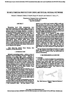
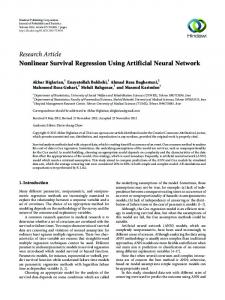
output layer and at least one feedback loop. A Multi Layer Perception (MLP) consists of an input layer, several hidden layers, and an output layer [3]. Node i, also called a neuron in a MLP network is shown in Figure 1. It includes a summer and a linear activation function g. The inputs xk, where k ranges from digit ‘1’ to digital ‘k’, the neuron are multiplied by weights wki and summed up together with the constant bias term θi. The resulting in is the input to the activation function g. The activation function is originally chosen to be a relay function, but for mathematical convenience a hyperbolic tangent (tanh) or a sigmoid function are most commonly used [11]. The mathematical model of a neuron is given by: N y i = g i = g ∑ W ji . X j + θ i i =1
(1)
MODELING OF INDUCTION MOTOR The space vector model of the induction motor is the lumped-parameter model with the largest use in the study and design of electrical drive applications. It is common to consider as a first approximation that the rotor windings and the stator windings have a sinusoidal distribution inside the motor and no magnetic saturation is present. Therefore, the magneto-motive force (MMF) space harmonics and slot harmonics are neglected. Although saturation is not taken into account, the model is considered to yield acceptable results for the study of common electric drive applications.
Figure 1: A Multi-Layer Perception (MLP) network with one hidden layer
2
SUST Journal of Engineering and Computer Science (JECS), Vol. 15, No. 2, 2014
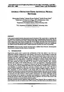
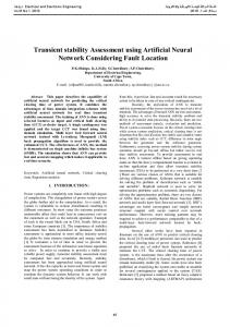
The induction motor space vector model is derived from the basic electrical equations describing each of the stator windings and each of the rotor windings [12]. The indirect vector control method is very popular in industrial applications. Figure 2 shows the phasor diagram of explaining indirect vector control.
iqr =
d ψ dr R + rψ dt Lr d ψ qr R + rψ dt Lr
r
+ ω sl )dt = θ r + θ sl
(2)
The rotor pole position is not absolute, but it is slipping with respect to the rotor frequency . The phasor diagram suggests that for decoupling control, the stator flux component of current ids should be aligned with the de axis, and the torque component of current iqs should be on the qe axis, the rotor circuit equations given in [13] are reproduced as (3) and (4). d ψ dr + R r i dr − (ω e − ω r )ψ qr = 0 dt d ψ qr + R r i qr − (ω e − ω r )ψ dr = 0 dt
dr
−
Lm R r i ds − ω sl ψ Lr
=0
(9)
qr
−
Lm R r i qs − ω sl ψ dr = 0 Lr
(10)
qr
Where, ω sl =ωe+ωr has been substituted. For decoupling control, it is desirable that: ψ qr = 0 (11) That is, dψ qr =0 (12) dt So, that the total rotor flux ψˆ r is directed at de axis. Substituting the above conditions in equations (9) and (10) getting: Lr dψˆ r + ψˆ r = Lmids (13) Rr dt L R ωsl = m r iqs (14) ψˆ r Lr where ψˆ r = ψ dr has been substituted. If rotor flux ψˆ r is costant, which is usually the case, then from equation (13):
The ds - qs axes are fixed on the stator, but the de – qe are rotating ahead of the dr – qr axes by the positive slip angle θsl corresponding to slip frequency, ωsl. Since the rotor pole is directed at the de axis and ωe=ωr+ωsl, the rotor flux position θe can be written as
∫ (ω
(8)
The rotor current in equation (3) and (4), which are inaccessible, can be eliminated with the help of equations (7) and (8) as:
Figure 2: Indirect vector control
θ e = ∫ ω e dt =
L 1 ψ qr − m iqs Lr Lr
ψˆ r = Lmids
(15)
A DC machine-like electro-mechanical model of an ideal vector-controlled drive can be drived using equation (13) and the following equations[5]: 3P L Te = m ψˆ r iqs (16) 2 2 Lr 2 dω r Te − TL = J (17) P dt where TL is the load torque.
(3) (4)
The rotor flux linkage (ψ dr ,ψ qr ) expressions can be given as: ψ dr = Lr idr + Lmids (5) ψ qr = Lr iqr + Lmiqs (6) From the above equations, the rotor d and q axis currents can be written as 1 L idr = ψ dr − m ids (7) Lr Lr
PROPORTIONAL INTEGRAL CONTROLLER Vector-controlled induction motor drive with a conventional proportional integral (PI) speed controller has used extensively in industrial applications, since PI controller is simple, easily implemented and effective if the load 3
SUST Journal of Engineering and Computer Science (JECS), Vol. 15, No. 2, 2014
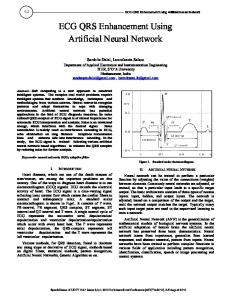
Figure 3: PI control system of induction motor drive
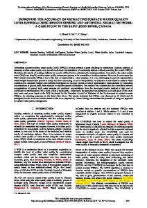
Figure 4: ANN control system of induction motor drive
network iteratively until the error between target vectors and the output of the ANN is less than an error goal. The most popular learning algorithm for multilayer networks is the back propagation algorithm and its variants [15]. The latter is implemented by many ANN software packages such as the ANN toolbox in MATLAB [8]. In this paper the ANNs control strategy has been implemented. Neural network has been devised having as inputs the speed error, the speed error change, the load torque, the stator
changes are small and the operating conditions do not force the system too far away from the linearized equilibrium point [14]. The analog transfer function of the proportionalintegral (PI) controller is: k s+a C (s ) = k p + i = k p (18) s s Figure 3 shows the SIMULINK model of the PI control system of induction motor drive.
NEURAL NETWORK CONTROLLER The ANN is trained by a learning algorithm which performs the adaptation of weights of the 4
SUST Journal of Engineering and Computer Science (JECS), Vol. 15, No. 2, 2014
direct axis current, and as output the reference electromechanical torque. The conventional PI controller shown in Figure 3 is replaced by the neural network controller and the simulation is performed as shown in Figure 4. The ANNs training with TRAINLM is given in Figure 5 and the SIMULINK block of ANN is generated as shown in Figure 6. The ANNs layers are shown in Figure 7 through to Figure 9 accordingly.
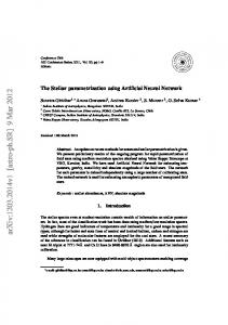
with k p = 13 , k p = 26 . The simulation results are shown in Figure 10 through to Figure 15. As shown in Figure 10, the speed of the motor wit PI controller, rises to 90% of its final speed at t=0.75s.
Figure 8: Layer-2
Figure 9: Layer-3 Figure 5: The training ANN
An external force of 2 [Nm] is applied to the induction motor and the speed response is shown in Figure 11, it seen that the result was very successful and the obtained result confirm the validity of the proposed control specifications. As shown in Figure 12, the speed of the motor with ANN controller, rises to 90% of its final speed at shorter time compared with PI controller (t=0.6s). An external force of 2 [Nm] is applied to the induction motor controlled with ANN controller and the speed is shown in Figure 13. In Figure 14 and Figure 15, one can observe the superior properties of the loop controlled by the NN control and the conventional PI controller.
Figure 6: ANN controller
Figure 7: Layer1
SIMULATION RESULTS The simulation of the system is conducted using SIMULINK Toolbox. The performances of the proposed controllers are evaluated under a variety of operating conditions. The PI controller has been tuned using trial and error to obtain a good speed response
Figure 10: Speed response with PI controller at no load
5
SUST Journal of Engineering and Computer Science (JECS), Vol. 15, No. 2, 2014
Figure 15: Speed response with PI and ANN controller at 2N.m load
Figure 11: Speed response with PI for 2N.m load torque disturbance
6. CONCLUSIONS The performance specifications taken into consideration are: the overshoot, rise time, settling time and steady state error. The performance of the proposed controllers has been evaluated under a variety of operating conditions of the drive system, and the results demonstrate the effectiveness of these control structures. A comparative study of the control strategies in term of performance has been conducted. An intelligent control system using a neural network controller has reduced peak overshoot, rise time and settling time compared to the system with a PI controller. It is observed that the speed of the machine remains constant with reduced overshoot using the neural network-based controller. In conclusion, the proposed Artificial Neural Network shows high performance and good control accuracy for the system.
Figure 12: Speed response with ANN controller at no load
REFERENCES [1] D. CASADEI¤, G. SERRA, A. TANI, and L. ZARRI “Assessment of direct torque control for induction motor drives” Bull. Pol. Ac.: Tech.; Vol. 54, No. 3, 2006; PP 237-254. [2] A. Miloudi, Y. Miloud and A. Draou “ A Neural Network Based Speed Control Design Strategy of an Indirect Vector Controlled Induction Machine Drive” Bologna Power Tech. Conference; Italy 2003. [3] Anuradha Tomar and Yog Raj “Various Control Techniques for Induction Motor Drive: A Brief Insight” IJERT; Vol. 1 Issue 5, July – 2012. [4] M. Zerikat, M. Bendjebbar and N. Benouzza “Dynamic Fuzzy-Neural Network Controller for Induction Motor Drive” world academy of science, engineering and technology volume 10 December 2005 ISSN 1307-6884 [5] Mouloud A. Denai and Sid A. Attia “Fuzzy and Neural Control of an Induction Motor” Int. J. Appl. Math. Comput. Sci., 2002, Volume 12. [6] R.Toufouti S.Meziane and H. Benalla “Direct Torque Control for Induction Motor Using Intelligent
Figure 13: Speed response with ANN for 2N.m load torque disturbance
Figure 14: Speed response with PI and ANN controller at no load
6
SUST Journal of Engineering and Computer Science (JECS), Vol. 15, No. 2, 2014 Techniques” Journal of Theoretical and Applied Information Technology; www.jatit.org pp 35-45. [7] Rajesh Kumar,R. A. Gupta and Rajesh S. Surjuse “Adaptive Neuro-Fuzzy Speed Controller for Vector Controlled Induction Motor Drive” Asian Power Electronics Journal, Vol. 3, No. 1, Sept 2009; pp 814. [8] Miroslaw Wlas, Zbigniew Krzemin´ski, Jarosław Guzin´ski, Haithem Abu-Rub and Hamid A. Toliyat, ″Artificial-NeuralNetwork-Based Sensorless Nonlinear Control of Induction Motors″ IEEE Transactions On Energy Conversion, Vol. 20, No. 3, September 2005. [9] Martin T. Hagan, "Neural networks for control", 2000. [10] Ghouili, J and Cheriti, A ″ Induction motor dynamic neural stator flux estimation using active and reactive power for direct torque control.″ PESC99. 30th Annual IEEE Volume 1, issue , Aug 1999 Page(s):501 - 505. [11] Miroslaw Wlas, Zbigniew Krzemin´ski, Jarosław Guzin´ski, Haithem Abu-Rub and Hamid A.
[12]
[13] [14]
[15]
7
Toliyat, ″Artificial Neural Network Based Sensorless Nonlinear Control of Induction Motors″ IEEE Transactions On Energy Conversion, Vol. 20, No. 3, September 2005. M. N. Cirstea, A. Dinu, J.G. Khor, M. Neural and Fuzzy Logic Control of Drives and Power Systems, McCormick, Newnes 2002. Bimal K.Bose, Modern Power Electronics and AC Drives, prentice Hall 2002. Omer Mahgoub Ahmed, "Fuzzy controller design of three phase induction motor", A thesis submitted in partial fulfillment of the requirement the degree of M.Sc. in electrical engineering, Sudan University of Science and Technology 2010. Ghouili, J and Cheriti, A″Induction motor dynamic neural stator flux estimation using active and reactive power for direct torque control″ Power Electronics Specialists Conference, 1999. PESC 99. 30th Annual IEEE Volume 1, Aug 1999.