polymers Article
Enhanced Water Vapor Transmission through Porous Membranes Based on Melt Blending of Polystyrene Sulfonate with Polyethylene Copolymers and Their CNT Nanocomposites Georgia Ch. Lainioti 1,2 , Giannis Bounos 2 , George A. Voyiatzis 2, * and Joannis K. Kallitsis 1,2, * 1 2
*
Department of Chemistry, University of Patras, GR-265 04 Rio-Patras, Greece;
[email protected] Foundation for Research and Technology Hellas-Institute of Chemical Engineering Sciences (FORTH-ICEHT), P.O. Box 1414, GR-265 04 Rio-Patras, Greece;
[email protected] Correspondence:
[email protected] (G.A.V.);
[email protected] (J.K.K.); Tel.: +30-261-096-5253 (G.A.V.); +30-261-096-2952 (J.K.K)
Academic Editor: Lloyd M. Robeson Received: 10 April 2016; Accepted: 5 May 2016; Published: 12 May 2016
Abstract: A novel concept for the use of an immiscible and non-meltable polymer, such as sodium polystyrene sulfonate (PSSNa), in order to prepare polyethylene non-woven breathable membranes is described. Membranes were fabricated by melt compounding of properly functionalized PE (P(E-co-AA)) and PSSNa (P(SSNa-co-GMA)) copolymers in the presence of water soluble polyethylene glycol (PEG). The inability of PSSNa derivatives to be melted was overcome by using PEG, which was easily meltable thus inducing PSSNa processability improvement. PEG was removed after membrane fabrication and therefore also acted as a porogen. Carbon nanotubes, functionalized with PSSNa moieties or alkyl groups, were also incorporated in the membranes with the aim of improving the porous connectivity and increasing the water vapor transmission rate. The morphology of the membranes was investigated through Scanning Electron Microscopy (SEM). Water vapor transmission rate (permeation) (WVTR) measurements for the porous membranes showed increased values in comparison with the neat PE ones. A further increase of WVTR was observed with the addition of CNTs to the polymer membranes. Keywords: breathable membranes; melt blending; polystyrene sulfonate; carbon nanotubes; water vapor transmission rate
1. Introduction In recent years, the most common and abundant group of commercially available membranes is represented by polymeric membranes, as they have a wide field of applications, including chemical [1], food [2] and pharmaceutical industries [3], water treatment [4], etc. The necessity for membranes with different separation properties is growing the interest in this research field. Several polymeric matrices have been used for the synthesis of breathable membranes. Microporous polyurethane membranes or poly(acrylonitrile-co-maleic acid) membranes modified with poly(ethylene glycol) have been used as membrane materials [5,6]. Moreover, polyolefins are highly attractive materials due to their abundance and low cost. Microporous films and composites have been made by using polyolefin material and inorganic fillers [7]. Special engineering fibers and their fabrics can be combined with these microporous films to achieve a variety of properties for practical applications. Hydrophilic polymers are interesting as membrane materials because of their reduced adsorption tendencies and high water (vapor) flux. Generally, a single membrane material hardly possesses all the desirable properties including film formation, good mechanical strength, thermal stability, chemical Polymers 2016, 8, 190; doi:10.3390/polym8050190
www.mdpi.com/journal/polymers
Polymers 2016, 8, 190
2 of 14
durability, etc., at the same time. As a result, the achievement of a hydrophobic–hydrophilic balance emerges as a property of high importance, as it will improve the membrane performance and satisfy different requirements. A well-known and simple technique to both accomplish this compromise and manufacture polymeric membranes is the production of polymer blends via melt-processing. The combination of two or more polymers via melt blending in order to obtain new polymers with improved properties is of utmost importance as it constitutes a practical and cost-effective method, although the challenge of their recycling grows. The compatibilization of immiscible polymers is of high scientific and industrial interest. The main strategies for that achievement are based (a) in the physical blending of the immiscible pairs with further addition of a pre-formed copolymer to compatibilize the blend (suitable block or graft copolymers that act as interfacial agents), and (b) in the reactive blending of relevant polymers bearing complementary reactive groups by the in situ generation of the required copolymers through polymer–polymer grafting reactions using functionalized polymers [8–10]. Despite the fact that many attempts have been made to maximize membrane performance by varying the molecular structure, polymers still exhibit a trade-off between permeability and selectivity [11]. However, due to the processing flexibility and low cost of polymers, polymeric membranes are still highly attractive for many industrial applications. Thus, efforts have been undertaken in order to use hybrid materials for the achievement of high permeability and selectivity in membrane applications [12,13]. Carbon nanotubes (CNTs) have attracted considerable attention from both academic and industrial sectors due to their outstanding properties making them promising materials in various fields. An approach that raised particular attention was the use of CNTs to control the water transport in membranes [14,15]. Many studies in the last few years suggest the use of nanotube networks and assemblies as a great tool for high efficiency water filtration [16–18]. However, for the development of polymer nanocomposites, the homogenous dispersion of CNTs in the polymer matrix to avoid aggregation problems is a prerequisite. For this reason, various functionalization procedures have been applied to CNTs to improve their compatibility with the polymer matrix [16] and, at the same time, to avoid any impact on their water permeability. Experimental studies on the water transport properties of polymer/CNT or other inorganic filler in Mixed Matrix Membranes are scarce [19] and results are somewhat contradictory. Experimental investigation on CNT–PVA membranes indicates that the water transport rate increases with filler concentration as a consequence of the reduced crystallinity of the polymer matrix [20]. The opposite result was obtained in an experimental study on composites of multiwalled carbon nanotubes with segmented polyurethane (MWCNT–SPU) membranes where the decrease of water permeability with the increase of filler content was attributed to the increased stiffness of the polymer chains [21]. With the incorporation of another type of inorganic filler like montmorillonite (MMT) in Hydroxypropylmethylcellulose (HPMC), Polyvinyl alcohol (PVA) and methylcellulose/pectin nanocomposite films [22–24], similar behavior of decreasing the WVTR with the incorporation of filler was observed. This water vapor barrier elevation of polymer/clay composite films is mainly attributed to the tortuous paths of water vapor diffusion due to the impermeable clay layers distributed in the polymer matrix which increase the effective diffusion path length [25]. In the present study, polyethylene membranes were prepared through reactive blending of sodium polystyrene sulfonate–glycidyl methacrylate and ethylene–acrylic acid copolymers in the presence of polyethylene glycol (PEG). The key achievement here is that, with this methodology, we made the reactive blending between sodium polystyrene sulfonate copolymers and polyethylene or polypropylene matrices possible. After PEG removal, new porous membranes as novel polyethylene non-woven breathable films were obtained. Taking advantage from the unique transport properties of the CNTs, CNTs were also incorporated in such porous membranes with the aim of improving the porous connectivity and increasing the water vapor transmission rate. The main objective of this paper is to provide an alternative technique for making cost-effective microporous films using conventional
Polymers 2016, 8, 190
3 of 14
polyolefin material. The significance of the method lies in the fact that, via a single step, the alteration of Polymers 2016, 8, 190 3 of 14 the PE porosity and the formation of interconnecting network among the microporous PE structure are simultaneously achieved. important, standardnetwork procedure of thethe biaxial the alteration of the Most PE porosity andthe theexpensive formationand of limited interconnecting among microporous PEasstructure areto simultaneously achieved. Mostnetwork important, expensiveinto and the limited drawing, reported a method create an interconnecting of the microvoids mineral standard of the biaxial drawing, reported as a methodinterfaces, to create an (CaCO PE films [26] produced by debonding at PE/mineral hasinterconnecting been avoided. 3 ) filledprocedure network of microvoids into the mineral (CaCO3) filled PE films [26] produced by debonding at
PE/mineral interfaces, has been avoided. 2. Materials and Methods 2. Materials and Methods 2.1. Materials
The monomers glycidyl methacrylate (GMA) and sodium styrene sulfonate (SSNa) and the 2.1. Materials initiator azobisisobutyronitrile (AIBN) were purchased from Sigma-Aldrich Co. (St. Louis, MO, monomers glycidyl (GMA) and sodium styrene sulfonate (SSNa) the USA) andThe used as received. Themethacrylate solvents N,N-dimethylformamide (DMF), acetone andand deuterated initiator azobisisobutyronitrile (AIBN) were purchased from Sigma-Aldrich Co. (St. Louis, MO, chloroform (CDCl3 ) were purchased from Fischer Scientific (Pittsburgh, PA, USA) and used as USA) and used as received. Theobtained solvents N,N-dimethylformamide (DMF), acetone deuterated unit. received. Ultra-pure water was by means of a SG apparatus waterand purification chloroform (CDCl3) were purchased from Fischer Scientific (Pittsburgh, PA, USA) and used as Polymers poly(ethylene-co-acrylic acid) and polyethylene glycol and 1,2-dimethylimidazole (DMI), received. Ultra-pure water was obtained by means of a SG apparatus water purification unit. 98% were purchased from Sigma-Aldrich Co. Multi-walled carbon nanotubes (MWCNTs) of 97% purity Polymers poly(ethylene-co-acrylic acid) and polyethylene glycol and 1,2-dimethylimidazole (DMI), as-produced diameter 15–35 nm) Co. were provided by Nanothinx S.A (Rio-Patras, Greece). 98% were(outer purchased from of Sigma-Aldrich Multi-walled carbon nanotubes (MWCNTs) of 97% A commercial breathable membrane, 25 µm-thick (coded Celgard 2400), was kindly provided purity as-produced (outer diameter of 15–35 nm) were provided by Nanothinx S.A (Rio-Patras, by Celgard LLC (Charlotte, NC,breathable USA) for membrane, comparison25in μm-thick water vapor transmission tests.was kindly Greece). A commercial (coded Celgard 2400), provided by Celgard LLC (Charlotte, NC, USA) for comparison in water vapor transmission tests.
2.2. Synthesis and Characterization of Copolymer through Free Radical Polymerization 2.2. Synthesis and Characterization of Copolymer through Free Radical Polymerization
The copolymers poly(sodium styrene sulfonate-co-glycidyl methacrylate) were synthesized Theradical copolymers poly(sodium methacrylate) were synthesized through free polymerization in styrene DMF/Hsulfonate-co-glycidyl 2 O, using AIBN as initiator. The synthetic procedure is through free radical polymerization in DMF/H 2O, using AIBN as initiator. The synthetic procedure illustrated in Scheme 1. The copolymer is denoted as P(SSNax-co-GMA(1 ´ x)), where x is the mol is illustrated in Scheme 1. The copolymer is denoted as P(SSNax-co-GMA(1−x)), where x is the mol fraction of SSNa units and (1 ´ x) is the mol fraction of GMA units, respectively, in the copolymer, fraction of SSNa units and (1 – x) is the mol fraction of GMA units, respectively, in the copolymer, as as determined by 1 H NMR characterization in D2 O. Briefly, the desired quantity of the two monomers determined by 1H NMR characterization in D2O. Briefly, the desired quantity of the two monomers (total (total monomer concentration 1 M) 1was in theinappropriate solvent, the solution was degassed, monomer concentration M) dissolved was dissolved the appropriate solvent, the solution was and the initiator AIBN (0.02 mol % over the total monomer concentration) was added. The The reaction degassed, and the initiator AIBN (0.02 mol% over the total monomer concentration) was added. was left to proceed vigorous stirring in an Arinatmosphere in an in oilan bath set atset80 ˝ C. reaction was leftovernight to proceedunder overnight under vigorous stirring an Ar atmosphere oil bath Afterat cooling downcooling to room temperature, the copolymers were recovered by precipitation in acetone, 80 °C. After down to room temperature, the copolymers were recovered by precipitation in acetone, filtered and driedoven in a vacuum filtered and dried in a vacuum at 60 ˝ Coven for at 2460 h.°C for 24 h. H3C
CH3 H2C
C
x C
O
+
SO3-Na+
GMA
O
O CH2
H2C
O SSNa
AIBN H2O/DMF, 80 oC
O SO3-Na+
1-x C
O P(SSNa-co-GMA)
Scheme 1. Reaction steps for the synthesis of the P(SSNa-co-GMA) copolymers.
Scheme 1. Reaction steps for the synthesis of the P(SSNa-co-GMA) copolymers.
A representative 1H NMR spectrum of the copolymer P(SSNa-co-GMA0.2) with a GMA content
1 NMR spectrum of the copolymer P(SSNa-co-GMA0.2) with a GMA content A representative 20%, is illustrated inHFigure 1, where the characteristic peaks of SSNa and GMA are observed. More 20%, specifically, is illustrated Figure 1, where the of SSNa and GMAAs arefar observed. theinpeaks at 6.0–8.0 ppm arecharacteristic assigned to thepeaks aromatic protons of SSNa. as GMA isMore concerned, from are the assigned methylenetobonded to the ester oxygen was observed at GMA 3.3 specifically, the signal peaks originating at 6.0–8.0 ppm the aromatic protons of SSNa. As far as is ppm (h type protons), the methine proton of the oxirane ring was observed at 2.9 ppm (f type concerned, signal originating from the methylene bonded to the ester oxygen was observed at 3.3 ppm protons), while protons for the methylene thewas ringobserved were observed at 2.7–2.8 ppm (g typewhile (h type protons), the two methine proton of the oxirane of ring at 2.9 ppm (f type protons), protons). The peak at 4.7 ppm is attributed to the deuterated water. two protons for the methylene of the ring were observed at 2.7–2.8 ppm (g type protons). The peak at 4.7 ppm is attributed to the deuterated water.
Polymers 2016, 8, 190
4 of 14
Polymers 2016, 8, 190
4 of 14
b e e'
a H3 C d
c x e e'
SO3 -Na+
1-x O
C O
D2O
h CH2 f
g O
e' h
e
10
8
6
4
fg
b,c,d a
2
0
Chemical shift (ppm) 1 HHNMR Figure NMRspectrum spectrum of Figure 1. 1. ofP(SSNa-co-GMA0.2). P(SSNa-co-GMA0.2). 1
2.3. Surface Modification of Carbon Nanotubes
2.3. Surface Modification of Carbon Nanotubes
2.3.1. Surface Polymerization of SSNa Monomer onto Carbon Nanotubes
2.3.1. Surface Polymerization of SSNa Monomer onto Carbon Nanotubes MWCNTs were initially functionalized with hydroxyl groups via diazonium chemistry, as
MWCNTs were initially with and hydroxyl groups diazonium chemistry, reported elsewhere [27,28], functionalized using 4-aminophenol isopentyl nitritevia (MWCNTs–OH). The as reported elsewhere [27,28], using 4-aminophenol and isopentyl nitrite hydroxyl-modified CNTs were then esterified with 2-chloropropionyl chloride for(MWCNTs–OH). the attachment of The hydroxyl-modified then esterified (MWCNTs-Init). with 2-chloropropionyl chloride for the attachment initiator groups CNTs on the were surface of nanotubes Furthermore, surface-initiated ATRP of was groups employed polymerization of hydrophilic sodium styrene sulfonate (SSNa) monomerATRP initiator on for thethe surface of nanotubes (MWCNTs-Init). Furthermore, surface-initiated onto modified CNTs (MWCNTs-g-PSSNa) [29,30]. sodium styrene sulfonate (SSNa) monomer onto was employed for the polymerization of hydrophilic modified CNTs (MWCNTs-g-PSSNa) [29,30]. 2.3.2. Functionalization of Carbon Nanotubes with Undecyl (C11-) Radicals
2.3.2. Functionalization of Carbon Nanotubes withelsewhere Undecyl[31], (C11in -) Radicals Based on a synthetic procedure mentioned a 1000-mL round bottom flask, equipped with a magnetic stirrer, 2 g of MWCNTs were dispersed in 900 mL of toluene under argon.
Based on a synthetic procedure mentioned elsewhere [31], in a 1000-mL round bottom flask, For the better dispersion of CNTs, the mixture was placed in an ultrasonic bath for 30 min. equipped with a magnetic stirrer, 2 g of MWCNTs were dispersed in 900 mL of toluene under Additionally, 2 g of lauroyl peroxide was added. Temperature was raised to 80 °C. Next, 1 g portions argon. theperoxide better dispersion ofsuccessively, CNTs, the mixture placed inTotal an ultrasonic bath of For lauroyl were added, every 2 hwas of synthesis. reaction time wasfor 15 30 h, min. ˝ C. Next, 1 g portions Additionally, 2 g of lauroyl peroxide was added. Temperature was raised to 80 and overall weight of consumed lauroyl peroxide was 6 g. The obtained undecyl-functionalized of lauroyl peroxide were added, successively, every 2 h of synthesis. Total reaction 15 h, and MWCNTs (MWCNTs-C 11) were vacuum filtered through Nylon membrane (200 nm).time Thewas obtained overall weight of11consumed lauroyl was 6 g. The MWCNTs-C was washed severalperoxide times with toluene and obtained hexane. undecyl-functionalized MWCNTs (MWCNTs-C11 ) were vacuum filtered through Nylon membrane (200 nm). The obtained MWCNTs-C11 2.4. Reactive Blending andwith Membrane Preparation was washed several times toluene and hexane. Before blending, polymers were dried at 60 °C, for 12 h in a vacuum oven. Blends of
2.4. Reactive Blending and Membrane Preparation P(ethylene-co-AA), P(SSNa-co-GMA), PEG and DMI [32] were prepared in a mixer equipped with a
cylindrical rotor at 180 °C, for about 20 min. A nitrogen blanket was used to minimize polymer Before blending, polymers were dried at 60 ˝ C, for 12 h in a vacuum oven. Blends of degradation. First, a mixture of P(SSNa-co-GMA) with PEG and DMI was added to the mixer and P(ethylene-co-AA), P(SSNa-co-GMA), PEG and DMI [32] were prepared in a mixer equipped with left to melt for 2 min. P(ethylene-co-AA) was then added and the sample processed under a rotation a cylindrical rotor at 180 ˝ C, for about 20 min. A nitrogen blanket was used to minimize polymer speed of 100 rpm for 18 min. After blending, films were prepared by compression molding process, degradation. First, a mixture P(SSNa-co-GMA) PEG and added the mixer through an Electric Thermo of hydraulic press, at 200 with °C, between twoDMI Teflonwas sheets with to a pressure of and left to15melt for 2 min. P(ethylene-co-AA) was then added and the sample processed under a rotation MPa for approximately 3 min. After removal from the hot press, the samples were quenched by speedimmersion of 100 rpm 18 min. After blending, films were prepared by compression moldingthat process, in for an ice-water bath. The resulting blend films were homogeneous with thickness ˝ ranged from 70 Thermo to 200 μm. The epoxide/acid was atwo crucial factor for the chemical through an Electric hydraulic press, at groups’ 200 C,ratio between Teflon sheets with a pressure the copolymers. For After the incorporation of the carbon nanotubes into thewere polymeric of 15 reaction MPa forofapproximately 3 min. removal from hot press, the samples quenched membranes, the above-mentioned procedure for the blend preparation was followed. The addition by immersion in an ice-water bath. The resulting blend films were homogeneous with thickness that of carbon nanotubes was done at the last stage and the concentration was 1 wt % of the weight of ranged from 70 to 200 µm. The epoxide/acid groups’ ratio was a crucial factor for the chemical reaction P(ethylene-co-AA). For obtaining porous structure via PEG extraction, membranes were immersed of the copolymers. For the incorporation of carbon nanotubes into the polymeric membranes, the in a water bath at 80 °C for 30 min. above-mentioned procedure for the blend preparation was followed. The addition of carbon nanotubes was done at the last stage and the concentration was 1 wt % of the weight of P(ethylene-co-AA). For obtaining porous structure via PEG extraction, membranes were immersed in a water bath at 80 ˝ C for 30 min.
Polymers 2016, 8, 190
Polymers 2016, 8, 190
5 of 14
5 of 14
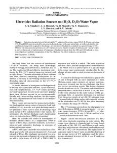
2.5. Characterization Techniques 2.5. Characterization Techniques 1 H NMR spectra were obtained from a Bruker Avance DPX 400 spectrometer (Billerica, MA, USA), 1H NMR spectra were obtained from a Bruker Avance DPX 400 spectrometer (Billerica, MA, with DMSO-d6, containing TMS as internal standard, and D2 O as solvent. USA), with DMSO-d6, containing TMS as internal standard, and D2O as solvent. Thermogravimetric analysis (TGA) was carried out in alumina crucibles in a Labsys™ TG (Caluire, Thermogravimetric analysis (TGA) was carried out in alumina crucibles in a Labsys™ TG France) apparatus of Setaram under nitrogen and at a heating rate of 10 ˝ C/min. (Caluire, France) apparatus of Setaram under nitrogen and at a heating rate of 10 °C/min. Scanning electron microscopy (SEM, Zeiss SUPRA 35VP instrument equipped with an EDS Scanning electron microscopy (SEM, Zeiss SUPRA 35VP instrument equipped with an EDS detector, Oberkochen, Germany) was performed to investigate the cross-section morphologies of detector, Oberkochen, Germany) was performed to investigate the cross-section morphologies of the composite membranes. All membrane samples, frozen in liquid nitrogen, were broken and the composite membranes. All membrane samples, frozen in liquid nitrogen, were broken and sputtered with gold to produce electric conductivity before SEM examination. The cross-section of the sputtered with gold to produce electric conductivity before SEM examination. The cross-section of membranes at the broken parts was finally examined by SEM. the membranes at the broken parts was finally examined by SEM. 2.6. Water Vapor Transmission Rate 2.6. Water Vapor Transmission Rate The technique used to measure water vapor transmission rate (WVTR) was the wet cup method The technique used to measure water vapor transmission rate (WVTR) washomemade the wet cupdish method described by ASTM E96/E96M-10 [33]. According to this method, an acetal filled described by ASTM E96/E96M-10 [33]. According to this method, an acetal homemade dish filled with distilled water is covered by the tested membrane and placed in a chamber under controllable with distilled is covered by the tested andconsist placedofina ahomemade chamber under controllable conditions of water humidity and temperature [34].membrane The chamber cartridge heater for conditions of humidity and temperature [34]. The chamber consist of a homemade cartridge heater temperature controlling, two inlets N2 for controlling the humidity (one for dry N2 and another one for temperature controlling, two inlets N 2 for controlling the humidity (one for dry N2 and another for N2 passed through water) and an axial fun for air circulation, as presented in Figure 2. During the one for N2 passed through an axial for airtest circulation, in Figure 2. experimental procedure thewater) weightand change of thefun complete assemblyas is presented measured every 10 min During the experimental procedure the weight change of the complete test assembly is measured by a computer-interfaced scale inside the chamber. The experimental conditions for all the examined every 10 min were by a computer-interfaced scale inside the chamber. experimental conditions for allis membranes 37 ˝ C and 50% relative humidity (RH). Water The vapor transmission rate (WVTR) the examined membranes were 37 °C and 50% relative humidity (RH). Water vapor transmission defined as the steady water vapor flow in unit of time through unit of area of a body, normal to specific rate (WVTR) is defined the steady water vapor flow in unit ofhumidity time through unitsurface. of area The of a WVTR body, parallel surfaces, underasspecific conditions of temperature and at each normal to specific parallel surfaces, under conditions temperature humidity at each was calculated from the steady-state regionspecific of the water losses of time curves. Theand examined membrane surface. The WVTR was calculated from the steady-state region of the water losses time curves. TheA 2 area was A = 10 cm . The slope of the water loss as a function of time normalized to the testing area 2. The slope of the water loss as a function of time examined membrane area was A = 10 cm was taken as the water vapor transmission rate (WVTR): normalized to the testing area A was taken as the water vapor transmission rate (WVTR): Mass H2 O lost Mass WVTR “ H O lost (1)(1) WVTR = time ˆ area time area ´2 ¨ min ´1 . Since −2·min −1. Since withunits unitsofofg·m g¨ m the thickness the films varied, the WVTR was normalized to the thickness of theoffilms varied, the WVTR was normalized to film with film thickness l in order to obtain specific water vapor transmission rate(l (l× ˆ WVTR)with withunits unitsof of thickness l in order to obtain the the specific water vapor transmission rate WVTR) ´ 2 ´ 1 −2 −1 µm¨ g¨ m·min ¨ min . μm·g·m .
Figure 2. Homemade Homemade experimental used forvapor water vapor transmission rate (WVTR) Figure 2. experimental setupsetup used for water transmission rate (WVTR) measurements. measurements.
3. Results and Discussion 3.1. Surface Modification of Carbon Nanotubes
Polymers 2016, 8, 190
6 of 14
3. Results and Discussion 3.1. Surface Modification of Carbon Nanotubes Polymers 2016, 8, 190
6 of 14
PSSNa-g-MWCNTs hybrids were prepared, as previously described [28], using atom transfer PSSNa-g-MWCNTs hybrids were prepared, as previously described [28], using atom transfer radical polymerization of SSNa on CNTs-initiator [27], derived from MWCNTs functionalized with radical polymerization of SSNa on CNTs-initiator [27], derived from MWCNTs functionalized with hydroxyl groups. Grafting polymerization styrene sulfonate monomer hydroxyl groups. Grafting polymerization of of sodium sodium styrene sulfonate monomer took took place place from from the surface of initiator-functionalized Functionalizations confirmed the surface of initiator-functionalizedcarbon carbon nanotubes. nanotubes. Functionalizations werewere confirmed with with thermogravimetric analysis, as as shown thermogravimetric analysis, shownininFigure Figure 3. 3. 100
% Weight
80
60
40
20
0 200
MWCNTs MWCNTs-g-C11 MWCNTs-g-PSSNa PSSNa 300
400 500 600 Temperature (oC)
700
800
3. TGA analysis of pristine MWCNTs and MWCNTs functionalized with the undecyl groups FigureFigure 3. TGA analysis of pristine MWCNTs and MWCNTs functionalized with the undecyl groups (MWCNTs-C11) and the sodium styrene sulfonate monomer (MWCNTs-g-PSSNa). (MWCNTs-C11 ) and the sodium styrene sulfonate monomer (MWCNTs-g-PSSNa).
The TGA results indicated that the mass losses of MWCNTs–OH and MWCNTs-Init were
The TGA results indicated the mass losses to ofpristine MWCNTs–OH MWCNTs-Init approximately 6% and 8% (datathat not shown), compared MWCNTs, and which is an indicator were of successful Moreover, ancompared additional weight loss of 4% for MWCNTs-g-PSSNa, approximately 6%functionalization. and 8% (data not shown), to pristine MWCNTs, which is an indicator compared to MWCNTs-Init, Moreover, reveals thean polymerization of sodium styrene (SSNa) of successful functionalization. additional weight loss of 4% forsulfonate MWCNTs-g-PSSNa, monomer onto the surface of CNTs-Init through ATRP. In another approach, MWCNTs were compared to MWCNTs-Init, reveals the polymerization of sodium styrene sulfonate (SSNa) monomer functionalized with undecyl (C11-) radicals generated by thermal decomposition of lauroyl peroxide. onto the surface of CNTs-Init through ATRP. In another approach, MWCNTs were functionalized with It is well known that one of the best methods for achieving homogeneous dispersion of CNTs in a undecyl (C11 -)matrix radicals by thermal decomposition lauroyl peroxide.ofItCNTs is well polymer is thegenerated functionalization of the MWCNTs [35,36]. of The functionalization withknown that one of the best methods for achieving homogeneous dispersion of CNTs in a polymer matrix is moieties that are structurally close to the polymer matrix ensures the compatibility of the dispersed the functionalization of the The functionalization of was CNTs with moieties that are nanomaterials with the MWCNTs matrix [37].[35,36]. The successful functionalization verified from TGA analysis, as shown Figure matrix 3. The TGA results a sufficient weight loss of 6.5% for with structurally close to the in polymer ensures thedemonstrate compatibility of the dispersed nanomaterials MWCNTs-C 11 compared to pristine MWCNTs, which correspond to the thermal disruption of the the matrix [37]. The successful functionalization was verified from TGA analysis, as shown in Figure 3. alkyl attachments. The TGA results demonstrate a sufficient weight loss of 6.5% for MWCNTs-C11 compared to pristine MWCNTs, which correspond to the thermal disruption of the alkyl attachments. 3.2. Chemical Structure of Membranes Development of Membranes breathable membranes by melt blending procedure is a demanding topic since 3.2. Chemical Structure of it requires the presence of a continuous matrix for mechanical integrity and controlled porosity in
Development breathable membranes meltvapor blending procedure is a demanding topic the presence ofof hydrophilic functionality forby water interactions and transport. Moreover, the since it requires the presence ofpolymer, a continuous matrix mechanical integrity and controlled in combination of a polar like PSSNa, withfor polyolefins results in low quality films due toporosity their inherentof immiscibility and the PSSNa inability to melt. In an attempt to overcome these limitations, the presence hydrophilic functionality for water vapor interactions and transport. Moreover, the we usedof properly PEPSSNa, (e.g., P(E-co-AA)) and PSSNa (P(SSNa-co-GMA)) forfilms the fixation combination a polarfunctionalized polymer, like with polyolefins results in low quality due to their of the hydrophilic PSSNa groups onto the polyolefin backbone through reactive blending. inherent immiscibility and the PSSNa inability to melt. In an attempt to overcome these limitations, In this study, melt blending of ethylene-acrylic acid and sodium styrene sulfonate-glycidyl we used properly functionalized PE (e.g., P(E-co-AA)) and PSSNa (P(SSNa-co-GMA)) for the fixation methacrylate copolymers was done with the use of 1,2-dimethylimidazole (DMI) as a catalyst. of the Imidazoles hydrophilic PSSNa groups onto the polyolefin backbone through reactive blending. have been reported as efficient catalysts for the epoxy/acid reaction, especially in Incommercial this study, melt blending ethylene-acrylic acid and sodium styrene sulfonate-glycidyl epoxy resin systemsof [38,39]. Our intent was obviously to achieve compatibilization of methacrylate copolymersand was done with the use 1,2-dimethylimidazole (DMI) as aacid catalyst. the two copolymers obtain homogenous films.ofThe chemical reaction between acrylic groups have (–COOH) P(E-co-AA)as and glycidylcatalysts methacrylate of P(SSNa-co-GMA) resulted in Imidazoles beenof reported efficient for groups the epoxy/acid reaction, especially in the generation of an systems in-situ graft copolymer blending.toThe inability of PSSNa commercial epoxy resin [38,39]. Our during intent the wasmelt obviously achieve compatibilization of the two copolymers and obtain homogenous films. The chemical reaction between acrylic acid
Polymers 2016, 8, 190
7 of 14
groups (–COOH) of P(E-co-AA) and glycidyl methacrylate groups of P(SSNa-co-GMA) resulted in the generation of an in-situ graft copolymer during the melt blending. The inability of PSSNa derivatives to be melted was overcome by using PEG that was easily meltable inducing thus the PSSNa processability improvement. PEG was added in order to reduce the melting temperature of the polymer, and also to act as a porogen, since it was removed during the water treatment of the membranes. Compositions of the blends and the water loss after PEG removal are collected in Table 1. Film quality for7all examined Polymers 2016, 8, 190 of 14 compositions was excellent. derivatives to be melted was overcome by using PEG that was easily meltable inducing thus the processability improvement. PEGwater was added in order to reduce the melting temperature of TablePSSNa 1. Composition of blends and loss of P(ethylene-co-AA0.28)/P(SSNa-co-GMA0.1 the polymer, and also to act as a porogen, since it was removed during the water treatment of the or 0.2)/PEG. membranes. Compositions of the blends and the water loss after PEG removal are collected in Table 1. Film quality for all examined compositions was excellent.
Membrane code
Polymers
Composition (wt %)
Table 1. Composition of blends and water loss of P(ethylene-co-AΑ0.28)/P(SSNa-co-GMA0.1 or P(ethylene-co-AA0.28)/P(SSNa-co-GMA0.2)/PEG 60/10/30 0.2)/PEG.
M1 M2 P(ethylene-co-AA0.28)/P(SSNa-co-GMA0.2)/PEG 50/10/40 M3Membrane code P(ethylene-co-AA0.28)/P(SSNa-co-GMA0.1)/PEG 60/10/30 Polymers Composition (wt %) Loss (%) M4 50/10/40 M1 P(ethylene-co-AA0.28)/P(SSNa-co-GMA0.1)/PEG P(ethylene-co-AΑ0.28)/P(SSNa-co-GMA0.2)/PEG 60/10/30 28 M2 P(ethylene-co-AA0.28)/P(SSNa-co-GMA0.1)/PEG P(ethylene-co-AΑ0.28)/P(SSNa-co-GMA0.2)/PEG 50/10/40 20 50/15/35 M5 M3 M4 M5 observed
P(ethylene-co-AΑ0.28)/P(SSNa-co-GMA0.1)/PEG P(ethylene-co-AΑ0.28)/P(SSNa-co-GMA0.1)/PEG P(ethylene-co-AΑ0.28)/P(SSNa-co-GMA0.1)/PEG there that PEG has been almost entirely
60/10/30 50/10/40 50/15/35 removed
Loss (%) 28 20 28 40 35
28 40 the35majority
It can be from of the membranes. However, in order to find the optimal conditions for the removal of PEG, immersion It can be observed there that PEG has been almost entirely removed from the majority of the time of the membrane versusintemperature of the water bath were examined. is worth mentioning membranes. However, order to find the optimal conditions for the removal of It PEG, immersion ˝ ˝ that PEGtime canofbetheextracted 24 htemperature in the caseofof C,bath whereas at 80 CItthe time mentioning can be reduced to membraneat versus the40 water were examined. is worth thatThis PEGprovides can be extracted at 24 h in the of 40 °C, whereas at 80 °C the timemembranes can be reduced 10–20 min. the possibility to case create controlled porosity in the bytochanging 10–20 min. This provides the possibility to create controlled porosity in the membranes by changing the temperature value or/and the time of immersion. Figure 4 depicts the membrane with composition the temperature value or/and the time of immersion. Figure 4 depicts the membrane with 60/10/30composition after the total removal of the porogen. 60/10/30 after the total removal of the porogen.
Figure 4. Membrane with P(ethylene-co-AΑc28)/P(SSNa-co-GMA0.2)/PEG composition 60/10/30 after
Figure 4. the Membrane with P(ethylene-co-AAc28)/P(SSNa-co-GMA0.2)/PEG composition 60/10/30 total removal of the water soluble polymer (PEG). after the total removal of the water soluble polymer (PEG). For the preparation of the above-mentioned membranes, several parameters were examined, such as the mixing duration of the materials, the order of addition of the polymers, the ratio of the For the preparation of the above-mentioned membranes, several parameters were examined, molar equivalents of active groups (acid/epoxide ratio), the percentage of GMA (10% or 20%) in the such as the mixing duration of theand materials, the or order of addition of the ratio of the P(SSNa-co-GMA) copolymer the presence absence of a catalyst. An polymers, optimizationthe of the acid/epoxideof ratio was held in order to find the best ratio), film quality. Moreover, a large quantity of DMI molar equivalents active groups (acid/epoxide the percentage of GMA (10% or 20%) in is necessary to activate the grafting reaction (moles of DMI > 20 mol of –COOH) [32]. the P(SSNa-co-GMA) copolymer and the presence or absence of a catalyst. An optimization of the Then, experiments were conducted in order to integrate modified carbon nanotubes in the acid/epoxide ratio was held in order to find the best film quality. Moreover, a large quantity of DMI is PE-g-PSSNa membranes. For this purpose, mixtures of the polymers P(ethylene-co-AA), necessaryP(SSNa-co-GMA), to activate the PEG grafting reactioncarbon (moles of DMI in > 20 mol of –COOH) [32]. and modified nanotubes different compositions were prepared, Then, experiments were conducted in order to integrate modified carbon nanotubes in which are presented in Table 2. The modification of the MWCNTs was performed with the water-soluble polymer PSSNa as well of as the the hydrophobic groups C11 the PE-g-PSSNa membranes. For (MWCNTs-g-PSSNa), this purpose, mixtures polymers P(ethylene-co-AA), (MWCNTs-g-C11). The films, as shown in Table 2, had very good homogeneity. Films were then P(SSNa-co-GMA), PEG and modified carbon nanotubes in different compositions were prepared, which immersed in distilled water for PEG removal and pore formation. Film quality for all examined are presented in Table 2. The modification of the MWCNTs was performed with the water-soluble compositions was excellent.
polymer PSSNa (MWCNTs-g-PSSNa), as well as the hydrophobic groups C11 (MWCNTs-g-C11 ). The films, as shown in Table 2, had very good homogeneity. Films were then immersed in distilled water for PEG removal and pore formation. Film quality for all examined compositions was excellent.
Polymers 2016, 8, 190
8 of 14
Polymers 2016, 8, 190
8 of 14
Table 2. Composition of of blends and water loss P(ethylene-co-AAc28)/P(SSNa-co-GMA0.1)/PEG Table 2. Composition blends and water lossofof P(ethylene-co-AΑc28)/P(SSNa-co-GMA0.1)/PEG and functionalized MWCNTs. and functionalized MWCNTs.
Composition (wt %) 60/10/30 60/10/30 50/10/40 50/10/40 50/15/35 50/15/35 60/10/30 60/10/30 50/10/40 50/15/35 50/10/40 50/15/35
Membrane code code Functionalized MWCNTs Membrane Functionalized MWCNTsComposition (wt %) M3-f -CNTs(PSSNa) MWCNTs-g-PSSNa M3-f-CNTs(PSSNa) MWCNTs-g-PSSNa M4-f -CNTs(PSSNa) MWCNTs-g-PSSNa M4-f-CNTs(PSSNa) MWCNTs-g-PSSNa M5-f -CNTs(PSSNa) MWCNTs-g-PSSNa MWCNTs-g-PSSNa M3-fM5-f-CNTs(PSSNa) -CNTs(C11 ) MWCNTs-g-C 11 M3-f-CNTs(C 11 ) MWCNTs-g-C 11 M4-f -CNTs(C ) MWCNTs-g-C 11 11 M5-f -CNTs(C MWCNTs-g-C M4-f-CNTs(C 11) MWCNTs-g-C 11 11 ) 11
Loss Loss (%) (%) 28 28 25 25 30 30 28 28 38 38 33 33
M5-f-CNTs(C11) MWCNTs-g-C11 3.3. Morphology of the Blends 3.3. Morphology of the Blends The morphological characterization of the membranes, after the removal of the water soluble of the membranes, afterscanning the removal of the water soluble polymerThe andmorphological the formationcharacterization of the porous structure, was done with electron microscopy (SEM). polymer and the formation of the porous structure, was done with scanning electron microscopy Figure 5 shows SEM photographs of the cross section of membranes with various blend compositions (SEM). Figure 5 shows SEM photographs of the cross section of membranes with various blend produced using DMI as a catalyst. Cross-sectional SEM images of the composite membranes exhibit a compositions produced using DMI as a catalyst. Cross-sectional SEM images of the composite porous structure at the surface skin layers of the membranes, in the range of µm. Moreover, it is worth membranes exhibit a porous structure at the surface skin layers of the membranes, in the range of mentioning that some macro voids have been appeared, revealing the inner structure of the membrane. μm. Moreover, it is worth mentioning that some macro voids have been appeared, revealing the In some cases, a uniform matrix has been developed, which is a strong evidence of the reaction of inner structure of the membrane. In some cases, a uniform matrix has been developed, which is a thestrong polymers bearing reactive groups. SEM micrographs evidently showed thatmicrographs after the melt evidence of the reaction of theThe polymers bearing reactive groups. The SEM blending of polymers and the removal of the water soluble PEG, a porous structure was created on the evidently showed that after the melt blending of polymers and the removal of the water soluble membranes with some limited interconnected pathways. PEG, a porous structure was created on the membranes with some limited interconnected pathways.
Figure 5. Cont. Figure 5. Cont.
Polymers 2016, 8, 190 Polymers 2016, 190 Polymers 2016, 8,8,190
9 of 14 9 of914of 14
Figure 5. SEM images in two different magnifications of the cross-section morphology of Figure 5.5.SEM images in two magnifications of the cross-section morphologymorphology of PE-g-PSSNa Figure SEM images in different two different magnifications of the cross-section of PE-g-PSSNa membranes with various blend compositions: (A) M1; (B) M3; (C) M4; (D) M5. membranes with various blend compositions: (A) M1; (B) M3; (C) M4; (D) M5. PE-g-PSSNa membranes with various blend compositions: (A) M1; (B) M3; (C) M4; (D) M5.
3.4. TGA Characterization 3.4. 3.4. TGA TGA Characterization Characterization The films after the removal of PEG were characterized with thermogravimetric analysis (TGA), after removal of characterized thermogravimetric (TGA), The films films after the the removal of PEG PEG were characterized with thermogravimetric analysis as The shown in Figure 6. TGA analysis waswere conducted under a with nitrogen atmosphere. Theanalysis heating (TGA), rate aswas shown in Figure 6. TGA analysis was conducted under a nitrogen atmosphere. The heating in Figure 6. TGA analysis was conducted under a nitrogen atmosphere. The heating 20 °C/min and the final temperature 800 °C. In Figure 6, a high initial decompositionrate ˝ rate was 20 ˝ C/min and temperature Figure high initial decomposition was 20 °C/min the the final temperature 800800 °C. C.In Figure 6,6, aa high decomposition temperature wasand observed atfinal 460 °C, which appeared inInall the porous synthesized membranes. ˝ temperature was observed weight at 460 loss C, was which appeared the membranes, porous synthesized Moreover, an intermediate observed for the porous comparedmembranes. with the °C, in all Moreover, an intermediate weight loss was observed for the porous membranes, compared TGA graphs of the copolymers. The residue of M3 and M5 at 500 °C was 21% and 25%, respectively, Moreover, an intermediate weight loss was observed for the porous membranes, compared with with the ˝ C was 21% and TGA graphs of the copolymers. The residue of M3 and M5 at 500 25%, respectively, whereas the residue of the copolymers P(SSNa-co-GMA0.1) and P(E-co-AA0.28) was, in that order, TGA graphs °C was 21% and 25%, respectively, 78% and 15%, respectively. Bearing inP(SSNa-co-GMA0.1) mind these values, asand well asP(E-co-AA0.28) the initial blend composition for whereas the residue ofofthe P(E-co-AA0.28) was,was, in that order, 78% whereas the residue thecopolymers copolymers P(SSNa-co-GMA0.1) and in that order, each membrane (the percentage of P(E-co-AA0.28)/P(SSNa-co-GMA0.1) was 60/10 for M3 and 50/15 and 15%, respectively. Bearing in mind these values, as well as the initial blend composition for each 78% and 15%, respectively. Bearing in mind these values, as well as the initial blend composition for for membrane M5), the theoretical weight residue for the porous membranes could be60/10 estimated. In this membrane (the percentage of P(E-co-AA0.28)/P(SSNa-co-GMA0.1) was for M3 and 50/15 for each (the percentage of P(E-co-AA0.28)/P(SSNa-co-GMA0.1) was 60/10 for M3context, and 50/15 the residue determined by the copolymers was 25% for M3 and 30% for M5; these values incontext, linethe M5), the the theoretical weight residue for the membranes could be estimated. In this context, for M5), theoretical weight residue for porous the porous membranes could be estimated. Inare this when determined compared toby the experimental ones. residue was 25% M5; are in are linein when the residue determinedthe bycopolymers the copolymers was for 25%M3 forand M330% andfor 30% forthese M5; values these values line compared to the experimental ones. when compared to the experimental ones. 100
% Weight % Weight
100 80 80 60 60 40 40 20 200 200 0 200
P(SSNa-co-GMA0.1) Porous membrane M5 Porous membrane M3 P(E-co-AA0.28) P(SSNa-co-GMA0.1)
Porous M5 300 membrane 400 500 600 Porous membrane M3 o Temperature ( C) P(E-co-AA0.28) 300
400
500
600
700
700
800
800
Figure 6. TGA analysis of the PE-g-PSSNa porous membranes and the copolymers o Temperature ( C) P(ethylene-co-AΑ0.28) and P(SSNa-co-GMA0.1).
Figure 6.6.TGA TGA analysis the PE-g-PSSNa porous membranes and theP(ethylene-cocopolymers analysis of theofPE-g-PSSNa porous membranes and the copolymers 3.5.Figure Water Vapor Transmission P(ethylene-co-AΑ0.28) and P(SSNa-co-GMA0.1). AA0.28) and P(SSNa-co-GMA0.1).
Water vapor transmission measurements were performed on porous PE-g-PSSNa membranes 3.5. Water Vapor Transmission obtained afterTransmission PEG removal. Membranes with various compositions, with and without the 3.5. Water Vapor incorporation of functionalized CNTs were tested. The water vapor transmission of these Water vapor vapor transmission transmission measurements measurements were were performed performed on on porous porous PE-g-PSSNa PE-g-PSSNa membranes membranes Water membranes was compared with the corresponding of pure polyethylene membrane and a obtained after PEG removal. Membranes with various compositions, with and without the obtained after PEG removal. with various compositions, withFigure and without commercially available porous Membranes membrane, the 25 μm-thick Celgard 2400 [40]. 7 depictsthe incorporation ofoffunctionalized functionalized CNTs were Thevapor watertransmission vapor transmission of these incorporation were tested.tested. The of membrane, these membranes representative curves showing CNTs the time dependence of water mass losses of pure PE and membranes was compared with the corresponding of pure polyethylene membrane and a was compared with the of pure 11polyethylene membranemembranes, and a commercially porous membranes M3,corresponding M5 and M5-f-CNTs(C ). For all the composite the rate ofavailable water commercially available porous membrane, the 25 μm-thick Celgard 2400 [40]. Figure 7 depicts loss was linear with after an Celgard initial period of about 2 h.7 depicts This initial period was curves attributed to porous membrane, the time 25 µm-thick 2400 [40]. Figure representative showing representative curves showing the time dependence of water mass losses of pure PE membrane, and the time dependence of water mass losses of pure PE membrane, and porous membranes M3, M5 and porous membranes M3, M5 and M5-f-CNTs(C11). For all the composite membranes, the rate of water loss was linear with time after an initial period of about 2 h. This initial period was attributed to
Polymers 2016, 8, 190
10 of 14
Polymers 2016, 8, 190 of 14 M5-f -CNTs(C 11 ). For all the composite membranes, the rate of water loss was linear with time10after an initial period of about 2 h. This initial period was attributed to temperature equilibration in the temperature equilibration all in the thecomposite sample dish. Furthermore, the composite exhibit sample dish. Furthermore, membranes exhibitall negligible swellingmembranes of ~7% during the negligible swelling of ~7% during the test procedure. test procedure.
Water Mass Losses (gr)
1,5
25mm-2400 CELGARD M5-f-CNTs M5 M3 PE
1,0
0,5
0,0
200
400
600
800 1000 1200 1400
Time (min)
Figure 7. Typical curves of water mass losses as a function function of of the the tested tested time. time.
Specific water water vapor vapor transmission transmission rates rates (Sp.WVTR) (Sp.WVTR) were calculated from the linear linear region region of of Specific were calculated from the the curve. The above-mentioned values, along with the composition and membrane thickness, are the curve. The above-mentioned values, along with the composition and membrane thickness, are −2·min ´−11.. presentedin inTable Table3.3.The Theextracted extractedSp.WVTR Sp.WVTRvalue value pure was found to be presented forfor pure PEPE was found to be 1.941.94 µm¨μm·g·m g¨ m´2 ¨ min This value forfor PEPE [41]. ForFor thethe porous membranes M3 This value is is in in good goodaccordance accordancewith withthe theliterature literaturevalue value [41]. porous membranes −2 −1 ´ 2 ´ 1 andand M5,M5, thethe Sp.WVTR and 18.05 18.05µm¨ μm·g·m worth ¨ min , respectively. M3 Sp.WVTRvalues valueswere were 11.18 11.18 and g¨ m ·min , respectively.ItIt is is worth mentioning that in general, the transmission of the water vapor is strongly related to the porous mentioning that in general, the transmission of the water vapor is strongly related to the porous structure as aswell wellasastoto hydrophilic groups contained in membranes. the membranes. the present structure thethe hydrophilic groups contained in the Thus,Thus, in thein present study, study, the transmission may be affected only by content, the PEGthe content, theofremoval of which creates the transmission may be affected not only not by the PEG removal which creates the porous the porousbut structure, butpercentage also by theofpercentage of thecopolymer hydrophilic copolymer P(SSNa-co-GMA) in structure, also by the the hydrophilic P(SSNa-co-GMA) in the membrane the membrane composition. As a result, the slight improvement in the Sp.WVTR value appeared at composition. As a result, the slight improvement in the Sp.WVTR value appeared at the M5 membrane theowed M5 membrane is mentioned owed to theparameters. above mentioned parameters. is to the above Table 3. Specific Specific water water vapor vapor transmission transmission rate rate (Sp.WVTR) (Sp.WVTR) values values of of the the examined examined membranes. membranes. Table 3.
Sample description Sample description PE PE2400 Celgard Celgard 2400 M3 M3 M5 M5** M5-f -CNTs(C11 M5-f-CNTs(C 11)) *
Composition (wt %) Thickness (μm) Sp.WVTR (μm·g·m−2·min−1) Thickness (µm) Sp.WVTR (µm¨ g¨ m´2 ¨ min´1 ) Pure 40 1.94 Pure– 40 25 1.94 42.88 – 25 42.88 60/10/30 11.18 60/10/30 70 70 11.18 50/15/35 18.05 50/15/35 260260 18.05 49/35/15/1 150150 53.13 49/35/15/1 53.13
Composition (wt %)
For data data reproducibility three identical M5 membranes of different batches and two identical M5-fidentical -CNTs * *For reproducibility three identical M5 membranes of different batches and two membranesmembranes of different batches were tested. M5-f-CNTs of different batches were tested.
Moreover, incorporation of undecyl-functionalized MWCNTsMWCNTs (MWCNTs-C Moreover, thethe incorporation of undecyl-functionalized (MWCNTs-C 11) in 11 ) in PE-g-PSSNa and the subsequent removal, PEG led toremoval, the formation theformation M5-f -CNTs(C membrane PE-g-PSSNa and thePEG subsequent led toofthe of the M5-f-CNTs(C 11) with type 11 ) type 2 ¨ min´1 , as shown amembrane substantialwith increase in the Sp.WVTR 53.13¨ µm¨value g¨ m´to in−1Table 3 for the a substantial increasevalue in thetoSp.WVTR 53.13·μm·g·m−2·min , as shown in M5-f ) membrane;11this value is increased factor of by ~2.9 compared to compared the value of Table-CNTs(C 3 for the11M5-f-CNTs(C ) membrane; this valueby is aincreased a factor of ~2.9 to the M5 (CNTs free)M5 membrane. From a theoretical pointa of view, considering non-porous domain value of the (CNTs free) membrane. From theoretical point of the view, considering the of M5-f -CNTs as a Mixed Matrix Membrane (MMM), these results can be explained by describing non-porous domain of M5-f-CNTs as a Mixed Matrix Membrane (MMM), these results can be the MMM by as adescribing two-phasethe system consisting of a polymer with of a second pseudo-dispersed explained MMM as a two-phase systemmatrix consisting a polymer matrix with a phase enhanced phase water vapor permeability [42]. The second phase is most[42]. likelyThe composed secondexhibiting pseudo-dispersed exhibiting enhanced water vapor permeability second of MWCNTs surrounding matrix interphase region. Interphase also act as fastInterphase diffusion phase is mostwith likely composed of MWCNTs with surrounding matrixpores interphase region. pores also act as fast diffusion channels, where the transport of penetrant molecules follow Knudsen diffusion, described by the following equation:
=
⁄3 8
⁄
⁄
1−
⁄2
(2)
Polymers 2016, 8, 190
11 of 14
channels, where the transport of penetrant molecules follow Knudsen diffusion, described by the following equation: ` ˘ ` ˘ Dk “ dp {3 p8RT{mq1{2 1 ´ σmol {2dp (2) where, dp is the pore diameter, while m and σmol are the mass and size of the penetrant molecule, respectively [43]. The enhanced water permeability of this second phase can be explained considering the specific properties of the water–CNT system as reported in the literature in a theoretical and experimental context. Enhanced “apparent” water solubility is a consequence of water vapor condensation on the nanotube surface, as suggested by molecular dynamic studies [44,45] and/or of a “vapor-liquid” phase transition by capillary effects at the nanotube interior, as experimentally observed by TEM analysis [46]. When formation of liquid water takes place, CNTs act as a fast pathway for these penetrant molecules: the atomic-scale smoothness of CNT walls facilitates molecular ordering phenomena inside the tube, which weaken the carbon–water interactions and establish a friction-less transport mechanism [47]. The exact underlying mechanism for water transport and the further quantitative analysis, however, is difficult to be explained in this stage. As already mentioned, the covalent functionalization of CNTs stands as a tool for obtaining both improved dispersion of CNTs and enhanced compatibility between polymers and nanotubes. This is due to the intermolecular interactions between polymer chains and functional groups on the surface of CNTs. The attachment to CNTs of alkyl chains that resemble the chemical structure of polyolefins is expected to reveal efficient interaction between nanocomposites and the polymer matrix. As a result, the incorporation of functionalized CNTs in the membranes leads to the improvement of the continuity of porous pathways. The low interfacial force between hydrophilic water molecules and smooth hydrophobic CNT’s inner walls contributes to fast water vapor transport directly through the inner tubes of CNTs [48–50]. It seems that water molecules instinctively flow into the internal CNTs by forming a one-dimensional chain due to its higher thermodynamical stability within CNTs [14,51]. Comparing the Sp.WVTR of M5-f -CNTs(C11 ) and 25 µm-thick Celgard 2400 membrane, we realized that the values are quite similar. It is worth noting that 2400 Celgard membrane is formed by film extrusion, annealing and stretching of polypropylene and shows a three dimensional microporous structure [52]. Here, we also show that by a melt blending-manufacturing-process, the increased water vapor transmission performance of M5-f -MWCNT-C11 membrane points out the potential of such composite membranes for advanced water vapor transport applications. 4. Conclusions In the present work, the incorporation of an immiscible and non-meltable polymer, like PSSNa, into a polyolefin matrix was achieved, through melt blending mediated by PEG. For this purpose, properly functionalized PE (e.g., P(E-co-AA)) and polystyrene sulfonate–glycidyl methacrylate copolymers were used. The integration of PSSNa to the PE matrix was done with the aid of the hydrophilic polymer PEG, which was subsequently removed to gain porosity in the membranes. In a further step, carbon nanotubes that have been successfully functionalized with PSSNa moieties or alkyl chain were incorporated to the membranes. As a result, a novel series of hydrophilic polymer membranes and hybrid polymer membranes were developed and their specific water vapor transmission rate (Sp.WVTR) was determined. The Sp.WVTR measurements for the porous membranes showed increased values in comparison with neat PE membranes. The incorporation of carbon nanotubes, functionalized with undecyl groups, enhanced the Sp.WVTR values revealing expectations toward breathable membrane applications. Acknowledgments: The present work was funded by GSRT under the action of Synergasia 2009 program (Development of advanced multi-functional non-woven products: 09SYN-1156). This program is co-funded by the European Regional Development Fund and national resources. It was also partially funded by PROENYL project within the KRIPIS action, funded by Greece and the European Regional Development Fund of the European Union under the O.P. Competitiveness and Entrepreneurship. Project title: “Advanced Energy Materials”. MIS Code: 448305. Thanks are given to Celgard LLC for providing free the Celgard 2400 product.
Polymers 2016, 8, 190
12 of 14
Author Contributions: Joannis K. Kallitsis and George A. Voyiatzis conceived and designed the experiments. Georgia Ch. Lainioti performed the experiments concerning the polymer synthesis, the functionalization of CNTs and the membrane preparation and wrote the manuscript. Giannis Bounos performed the water vapor transmission measurements and wrote part of the manuscript. Conflicts of Interest: The authors declare no conflict of interest. The founding sponsors had no role in the design of the study; in the collection, analyses, or interpretation of data; in the writing of the manuscript, and in the decision to publish the results.
References 1. 2. 3. 4. 5. 6. 7. 8. 9. 10. 11. 12. 13. 14. 15.
16. 17. 18.
19. 20.
Sereewatthanawut, I.; Boam, A.T.; Livingston, A.G. Polymeric membrane nanofiltration and its application to separations in the chemical industries. Macromol. Symp. 2008, 264, 184–188. [CrossRef] Mondal, S.; Cassano, A.; Tasselli, F.; De, S. A generalized model for clarification of fruit juice during ultrafiltration under total recycle and batch mode. J. Membr. Sci. 2011, 366, 295–303. [CrossRef] Kim, J.H.; Kim, J.H.; Jegal, J.; Lee, K.H. Optical resolution of α-amino acids through enantioselective polymeric membranes based on polysaccharides. J. Membr. Sci. 2003, 213, 273–283. [CrossRef] Taylor, J.S.; Jacobs, E.P. Reverse Osmosis and Nanofiltration. In Water Treatment Membrane Processes; Mallevialle, J., Odendaal, P.E., Wiesner, M.R., Eds.; McGraw-Hill: New York, NY, USA, 1996. Tan, K.; Obendorf, S.K. Surface modification of microporous polyurethane membrane with poly(ethylene glycol) to develop a novel membrane. J. Membr. Sci. 2006, 274, 150–158. [CrossRef] Nie, F.Q.; Xu, Z.K.; Yang, Q.; Wu, J.; Wan, L.S. Surface modification of poly(acryloniterrile-co-maleic acid) membranes by the immobilization of poly(ethylene glycol). J. Membr. Sci. 2004, 235, 147–155. [CrossRef] Wu, P.C.; Jones, G.; Shelley, C.; Woelfli, B. Novel microporous films and their composites. J. Eng. Fiber. Fabr. 2007, 2, 49–59. Ciardelli, F., Penczek, S., Eds.; Modification and Blending of Synthetic and Natural Macromolecules; Kluwer Academic Publishers: Dordrecht, The Netherlands, 2004; pp. 155–199. Koulouri, E.G.; Georgaki, A.X.; Kallitsis, J.K. Reactive compatibilization of aliphatic polyamides with functionalized polyethylenes. Polymer 1997, 38, 4185–4192. [CrossRef] Gravalos, K.G.; Kallitsis, J.K.; Kalfoglou, N.K. In situ compatibilization of poly(ethylene terephthaIate)/ poly(ethylene-co-ethyl acrylate) blends. Polymer 1995, 36, 1393–1399. [CrossRef] Geise, G.M.; Park, H.B.; Sagle, A.C.; Freeman, B.D.; McGrath, J.E. Water permeability and water/salt selectivity trade off in polymers for desalination. J. Membr. Sci. 2011, 369, 130–138. [CrossRef] Vankelecom, I.F.J.; Merckx, E.; Luts, M.; Uytterhoeven, J.B. Incorporation of zeolites in polyimide membranes. J. Phys. Chem. 1995, 99, 13187–13192. [CrossRef] Ballinas, L.; Torras, C.; Fierro, V.; Garcia-Valls, R. Factors influencing activated carbon polymeric composite membrane structure and performance. J. Phys. Chem. Sol. 2004, 65, 633–637. [CrossRef] Kim, S.; Jinschek, J.R.; Chen, H.; Sholl, D.S.; Marand, E. Scalable fabrication of carbon nanotube/polymer nanocomposite membranes for high flux gas transport. Nano Lett. 2007, 7, 2806–2811. [CrossRef] [PubMed] Baek, Y.; Kim, C.; Seo, D.K.; Kim, T.; Lee, J.S.; Kim, Y.H.; Ahn, K.H.; Bae, S.S.; Lee, S.C.; Lim, J.; et al. High performance and antifouling vertically aligned carbon nanotube membrane for water purification. J. Membr. Sci. 2014, 460, 171–177. [CrossRef] Yin, J.; Zhu, G.; Deng, B. Multi-walled carbon nanotubes (MWNTs)/polysulfone (PSU) mixed matrix hollow fiber membranes for enhanced water treatment. J. Membr. Sci. 2013, 437, 237–248. [CrossRef] Qiu, S.; Wu, L.; Pan, X.; Zhang, L.; Chen, H.; Gao, C. Preparation and properties of functionalized carbon nanotube/PSF blend ultrafiltration membranes. J. Membr. Sci. 2009, 342, 165–172. [CrossRef] Li, S.; Liao, G.; Liu, Z.; Pan, Y.; Wu, Q.; Weng, Y.; Zhang, X.; Yang, Z.; Tsui, O.K.C. Enhanced water flux in vertically aligned carbon nanotube arrays and polyethersulfone composite membranes. J. Mater. Chem. A 2014, 2, 12171–12176. [CrossRef] Ismail, A.F.; Goh, P.S.; Sanip, S.M.; Aziz, M. Transport and separation properties of carbon nanotube-mixed matrix membrane. Sep. Purif. Technol. 2009, 70, 12–26. [CrossRef] Choi, J.H.; Legal, J.; Kim, W.N. Modification of performances of various membranes using MWCNTs as a modifier. Macromol. Symp. 2007, 249–250, 610–617. [CrossRef]
Polymers 2016, 8, 190
21.
22.
23.
24.
25.
26.
27. 28. 29. 30.
31.
32. 33. 34.
35. 36. 37.
38.
39. 40.
13 of 14
Mondal, S.; Hu, J.L. Microstructure and water vapor transport properties of functionalized carbon nanotube-reinforced dense segmented polyurethane composite membranes. Polym. Eng. Sci. 2008, 48, 1718–1724. [CrossRef] Mondal, D.; Bhowmick, B.; Mollick, M.M.R.; Maity, D.; Mukhopadhyay, A.; Rana, D.; Chattopadhyay, D. Effect of clay concentration on morphology and properties of hydroxypropylmethyl cellulose films. Carbohydr. Polym. 2013, 96, 57–63. [CrossRef] [PubMed] Mondal, D.; Mollick, M.M.R.; Bhowmick, B.; Maity, D.; Bain, M.K.; Rana, D.; Mukhopadhyay, A.; Dana, K.; Chattopadhyay, D. Effect of poly(vinyl pyrrolidone) on the morphology and physical properties of poly(vinyl alcohol)/sodium montmorillonite nanocomposite films. Prog. Nat. Sci. Mater. Int. 2013, 23, 579–587. [CrossRef] Saha, N.R.; Sarkar, G.; Roy, I.; Rana, D.; Bhattacharyya, A.; Adhikari, A.; Mukhopadhyay, A.; Chattopadhyay, D. Synthesis and characterization of methylcellulose/pectin/montmorillonite nanocomposite films and their application possibilities. Carbohydr. Polym. 2016, 136, 1218–1227. [CrossRef] [PubMed] Mondal, D.; Bhowmick, B.; Mollick, Md.M.R.; Maity, D.; Saha, N.R.; Rangarajan, V.; Rana, D.; Sen, R.; Chattopadhyay, D. Antimicrobial activity and biodegradation behaviour of poly(butylene adipate-co-butylene terephthalate)/clay nanocomposites. J. Appl. Polym. Sci. 2014, 131, 40079. [CrossRef] Hale, W.R.; Dohrer, K.K.; Tant, M.R.; Sand, I.D. A diffusion model for water vapor transmission through microporous polyethylene /CaCO3 films. Coll. Surf. A Physiochem. Eng. Asp. 2001, 187–188, 483–491. [CrossRef] Hudson, J.L.; Casavant, M.J.; Tour, J.M. Water-soluble, exfoliated, nonroping single-wall carbon nanotubes. J. Am. Chem. Soc. 2004, 126, 11158–11159. [CrossRef] [PubMed] Usrey, M.L.; Lippmann, E.S.; Strano, M.S. Evidence for a two-step mechanism in electronically selective single-walled carbon nanotube reactions. J. Am. Chem. Soc. 2005, 127, 16129–16135. [CrossRef] [PubMed] Kong, H.; Gao, C.; Yan, D. Functionalization of multiwalled carbon nanotubes by atom transfer radical polymerization and defunctionalization of the products. Macromolecules 2004, 37, 4022–4030. [CrossRef] Koromilas, N.D.; Lainioti, G.C.; Gialeli, C.; Barbouri, D.; Kouravelou, K.B.; Karamanos, N.K.; Voyiatzis, G.A.; Kallitsis, J.K. Preparation and toxicological assessment of functionalized carbon nanotube-polymer hybrids. PLoS ONE 2014, 9, e107029. [CrossRef] [PubMed] Koval’chuk, A.A.; Shevchenko, V.G.; Shchegolikhin, A.N.; Nedorezova, P.M.; Klyamkina, A.N.; Aladyshev, A.M. Effect of Carbon nanotube functionalization on the structural and mechanical properties of polypropylene/MWCNT composites. Macromolecules 2008, 41, 7536–7542. [CrossRef] Pire, M.; Norvez, S.; Iliopoulos, I.; Rossignol, B.; Leibler, L. Imidazole-promoted acceleration of crosslinking in epoxidized natural rubber/dicarboxylic acid blends. Polymer 2011, 52, 5243–5249. [CrossRef] Standard test methods for water vapor transmission of materials, ASTM E96/E96M-10. Available online: http://www.astm.org/Standards/E96.htm (accessed on 10 April 2016). Andrikopoulos, K.S.; Bounos, G.; Tasis, D.; Sygellou, L.; Drakopoulos, V.; Voyiatzis, G.A. The effect of thermal reduction on the water vapor permeation in graphene oxide membranes. Adv. Mater. Interfaces 2014, 1. [CrossRef] Wang, Y.; Wu, J.; Wei, F. A treatment method to give separated multi-walled carbon nanotubes with high purity, high crystallization and a large aspect ratio. Carbon 2003, 41, 2939–2948. [CrossRef] Guo, G.; Yang, D.; Wang, C.; Yang, S. Fishing polymer brushes on single-walled carbon nanotubes by in-situ free radical polymerization in a poor solvent. Macromolecules 2006, 39, 9035–9040. [CrossRef] Ko, J.H.; Yoon, C.S.; Chang, J.H. Polypropylene nanocomposites with various functionalized-multiwalled nanotubes: Thermomechanical properties, morphology, gas permeation, and optical transparency. J. Polym. Sci. Part B 2011, 49, 244–254. [CrossRef] Merfeld, G.; Molaison, C.; Koeniger, R.; Acar, A.E.; Mordhorst, S.; Suriano, J.; Irwin, P.; Warner, R.S.; Gray, K.; Smith, M.; et al. Acid/epoxy reaction catalyst screening for low temperature (120 ˝ C) powder coatings. Prog. Org. Coat. 2005, 52, 98–109. [CrossRef] Blank, W.J.; He, Z.A.; Picci, M. Catalysis of the epoxy-carboxyl reaction. J. Coat. Tech. 2002, 74, 33–41. [CrossRef] Hu, Y.; Topolkaraev, V.; Hiltner, A.; Baer, E. Measurement of water vapor transmission rate in highly permeable films. J. Appl. Polym. Sci. 2001, 81, 1624–1633. [CrossRef]
Polymers 2016, 8, 190
41. 42. 43. 44. 45. 46. 47. 48. 49. 50. 51. 52.
14 of 14
Tock, R.W. Permeabilities and water vapor transmission rates for commercial polymer films. Adv. Polym. Tech. 1983, 3, 223–231. [CrossRef] Aroon, M.A.; Ismail, A.F.; Matsuura, T.; Montazer-Rahmati, M.M. Performance studies of mixed matrix membranes for gas separation: A review. Sep. Purif. Technol. 2010, 75, 229–242. [CrossRef] Cunningham, R.E.; Williams, R.J.J. Diffusion in Gases and Porous Media; Plenum Press: New York, NY, USA, 1980. Kalka, A.; Garde, S.; Hummer, G. Osmotic Water Transport through carbon nanotubes membranes. Proc. Natl. Acad. Sci. USA 2003, 100, 10175–10180. Yzeiri, I.; Patra, N.; Kràl, P. Porous carbon nanotubes: Molecular adsorption, transport and separation. J. Chem. Phys. 2014, 140, 104704. [CrossRef] [PubMed] Gogotsi, Y.; Libera, J.A.; Guvenc-Yazicioglu, A.; Megaridis, C.M. In situ multiphase fluid experiments in hydrothermal carbon nanotubes. Appl. Phys. Lett. 2001, 79, 1021–1023. [CrossRef] Mao, Z.; Sinnot, S.B. A computational study of molecular diffusion and dynamic flow through carbon nanotubes. J. Phys. Chem. B 2000, 104, 4618–4624. [CrossRef] Holt, J.K.; Noy, A.; Huser, T.; Eaglesham, D.; Bakajin, O. Fabrication of a carbon Nanotube-embedded silicon nitride membrane for studies of nanometer-scale mass transport. Nano Lett. 2004, 4, 2245–2250. [CrossRef] Joseph, S.; Aluru, N. Why are carbon nanotubes fast transporters of water? Nano Lett. 2008, 8, 452–458. [CrossRef] [PubMed] Whitby, M.; Quirke, N. Fluid flow in carbon nanotubes and nanopipes. Nat. Nanotechnol. 2007, 2, 87–94. [CrossRef] [PubMed] Pascal, T.A.; Goddard, W.A.; Jung, Y. Entropy and the driving force for the filling of carbon nanotubes with water. Proc. Natl. Acad. Sci. USA 2011, 108, 11794–11798. [CrossRef] [PubMed] Sawyer, L.C.; Grubb, D.T.; Meyers, G.F. Polymer Microscopy, 3rd ed.; Springer: Berlin, Germany, 2008. © 2016 by the authors; licensee MDPI, Basel, Switzerland. This article is an open access article distributed under the terms and conditions of the Creative Commons Attribution (CC-BY) license (http://creativecommons.org/licenses/by/4.0/).