FINDING MIMO: A PROPOSED MODEL FOR INCORPORATING MULTIPLE INPUT, MULTIPLE OUTPUT TECHNOLOGY INTO SOFTWARE DEFINED RADIOS Lee Pucker (Spectrum Signal Processing Inc., Burnaby, British Columbia, Canada;
[email protected]) ABSTRACT Multiple Input, Multiple Output (MIMO) technology offers the potential for a significant increase in capacity and performance within a given bandwidth and power budget. However, these benefits must be weighed against the cost of the multiple RF front ends and additional processing necessary in supporting MIMO systems. The creation of a cost effective MIMO system can be facilitated through the use of software defined radio technology. This technology allows systems to be fielded today supporting contemporary waveforms/air interface standards, with MIMO technology added as a future upgrade as the technology matures. A key enabling technology in supporting MIMO in the proposed SDR architecture is the use of a switched-fabric interconnect, such as RapidIO. RapidIO can be utilized to support the dedicate processing model inherent in traditional transceiver designs, and allows the amalgamation of received signals from each antenna into common space-time processing elements for future MIMO applications. 1. INTRODUCTION Significant attention has been given of late to Multiple Input, Multiple Output wireless technologies [1, 2, 3, 4, 5]. These technologies have the ability to provide a significant increase in raw data throughput in spectrally limited environments, while at the same time providing immunity to the multipath effects common in urban settings. As such, MIMO technology has been suggested for use in beyond 3G (B3G) and 4G cellular communications, automobile communications, wireless local and wide area networks, and military communications. Unfortunately, much of the practical work in MIMO is still in the research stage, and as such is not yet mature enough to drive requirements into the development and production of many types of wireless systems. For example, the DARPA Mobile Networked MIMO (MNM) Program is not expected to complete its phase 2 development until some time in 2006 [6]. This will obviously be too late for specification in legacy radio acquisitions, and may be too late for many new initiatives scheduled in upcoming years.
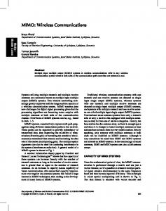
Given the benefits inherent in a MIMO based architecture but lack of maturity in MIMO technology, a question is raised as to how MIMO capabilities can be inserted into radio systems in a cost effective manner after those radios are already in service. This paper explores this question and proposes a model using software defined radio technology as a key enabler in allowing today's emerging wireless systems to support the future insertion of MIMO technology while minimizing overall capital investment. 2. OVERVIEW OF MIMO TECHNOLOGY The capacity of a wireless link is generally measured in bits per second per Hertz (b/s/Hz). The methods available to increase this capacity in a traditional Single Input, Single Output (SISO) wireless system are fairly limited: increase the bandwidth, allowing a corresponding increase in the bits per second, or increase the transmit power, allowing a higher level modulation scheme to be utilized for a given bit error rate, effectively increasing the bits per second within the same bandwidth. The problem with both of these techniques is that any increase in power or bandwidth can negatively impact other communications systems operating in adjacent spectral channels or within a given geographic area. As such, bandwidth and power for a given communications system are generally well regulated, limiting the ability of the system to support any increase in capacity or performance. MIMO technologies overcome the deficiencies of these traditional methods through the use of spatial diversity [3, 4]. Data in a MIMO system is transmitted over T transmit antennas through what is referred to as a “MIMO channel” to R receive antennas supported by the receiver terminal (see Figure 1). If the antennas within the transmit array and the antennas within the receive array are spaced sufficiently far apart, the signals traveling between the various transmit and receive antennas through the MIMO channel will fluctuate or fade in an independent manner. The transmitted data can therefore be encoded, using a so-called space-time code, to make use of this spatial diversity and allow processing at the receiver to extract the underlying data. The specific coding scheme utilized in the MIMO system is selected based on the target performance, the
Proceeding of the SDR 05 Technical Conference and Product Exposition. Copyright © 2005 SDR Forum. All Rights Reserved
acceptable level of computational complexity in the receiver’s signal processing subsystem, and the level of a priori knowledge of the transmission channel. Some schemes, referred to as space-time diversity codes, optimize for “diversity order”, which defines the performance gain that can be obtained through the number of decorrelated spatial branches that can be achieved through the MIMO channel. Other schemes, referred to as Spatial Multiplexing, optimize for channel capacity. Both of these types of schemes are discussed with additional detail below. These schemes can be used in combination to obtain the benefits accrued by both. Ultimately, the space-time coding scheme operating in conjunction with the MIMO channel allows the MIMO based system to support a significant increase in both performance and capacity over an equivalent SISO system while maintaining the same bandwidth and power.
antennas. Decoding of a space-time blocking code can also be done using a maximum likelihood detector, but other techniques can also be employed [3,4]. Space-time diversity codes support a symbol rate of at most one symbol per symbol period [7]. However, the improvement in signal to noise ratio at the receiver using space-time diversity coding can be quite high, with one paper reporting up to 16dB improvement for a two transmit and two receive antenna system [10]. This improvement allows an increase in the number of bits transmitted per symbol period while maintaining the same bandwidth, transmit power and bit error ratio, thus improving the capacity of the wireless link. It can also be used to extend distance over which a symbol can be transmitted, again while maintaining bandwidth, transmit power and bit error rate performance. This can improve the transmitter to receiver ratios, lowering site count and associated periodic costs.
Antenna 1
2.2 Spatial Multiplexing Input Data Stream
Demultiplex, Modulate/ Symbol Map, Space Time Encode
Antenna 2
MIMO Channel
Antenna 1
Space Time Processing, Demodulation
Recovered Data Stream
Antenna R Antenna T
Figure 1: Conceptual Diagram of a MIMO System
2.1 Space-Time Diversity Coding In space-time diversity coding, each modulated symbol is encoded and transmitted from each of the transmit antennas [7]. This maximizes the total available spatial diversity from the MIMO channel, on a per symbol basis, offering a significant increase in bit error rate performance over an equivalent SISO channel operating at the same transmit power. Space-time diversity coding works with any number of transmit or receive antennas, with the total diversity order equal to T*R [3]. Various space-time coding schemes have been developed for use in space-time diversity coding. In one of the earlier schemes, referred to as Delay Diversity, each symbol sent on one antenna is delayed by a symbol period and then sent on another antenna [8]. This scheme is a simple example of a space-time trellis code (STTC), and is typically decoded through the use of a fairly complex maximum likelihood sequence estimator in the front-end of the receiver. One of the more popular schemes for spacetime diversity coding is the Alamouti scheme [9]. This scheme utilizes a simple space-time block code (STBC) that encodes two modulated symbols into a matrix that is two rows by two columns in size. During each symbol period, the contents of a row are transmitted via the corresponding
Spatial multiplexing maximizes the link capacity that is sent over a given bandwidth by transmitting a different symbol on each antenna during each symbol period [3, 4]. Thus the number of symbols transmitted per symbol period is equal to the number of transmit antennas. For spatial multiplexing to work, the number of receive antennas must be greater than or equal to the number of transmit antennas. The spacetime code in a spatial multiplexing scheme is inherent in the multiplexing function [8]. The predominant encoding schemes associated with spatial multiplexing break into two types: horizontal encoding and vertical encoding (see Figure 2) [4, 8]. In horizontal encoding, the bit stream to be transmitted is demultiplexed into T separate data streams. Each of these data streams is then temporally encoded, interleaved and converted to transmission symbols, with different modulation schemes allowed on each transmit channel. In contrast, in vertical encoding, the bit stream to be transmitted is encoded using a space-time block code and then converted into transmission symbols. The transmission symbols are then demultiplexed into T bit streams and transmitted. Vertical encoding offers improved diversity gain over horizontal encoding because each data bit can be spread across all of the transmit antennas. However horizontal encoding accrues an advantage in receiver complexity in that the individual data streams are decoded separately, typically using a relatively simple linear receiver, such as the Zero Forcing receiver or Minimum Mean Squared Error receiver outlined in [3]. Vertical encoding, on the other hand requires joint decoding at the receiver, which significantly increases receiver complexity [11].
Proceeding of the SDR 05 Technical Conference and Product Exposition. Copyright © 2005 SDR Forum. All Rights Reserved
In p u t D a ta S tre a m
D e m u l ti p le x
T e m p o ra l E ncode & I n te le a v e
M o d u la t e
U p c o n v e rt & T r a n s m it
A n te n n a 1
T e m p o ra l E ncode & In te le a v e
M o d u la t e
U p c o n v e rt & T r a n s m it
A n te n n a 2
T e m p o ra l E ncode & I n te le a v e
M o d u la t e
U p c o n v e rt & T r a n s m it
A n te n n a T
against the additional up-front capital costs associated with utilizing multiple RF front-ends in supporting the MIMO channel. For terminal devices that are mass produced but typically only support a single carrier, this cost benefit can likely only be realized through the use of a MIMO ASSP such as the one being developed by Lucent for WiMAX communications [16].
H o r iz o n t a l E n c o d i n g
ADC/DAC
IF Processing/ Channelizer 3
ADC/DAC
IF Processing/ Channelizer N
el 2 ann Ch 1
Payload Data and Control Transport
Rest of System
lM ne an Ch
RF XCVR3
Ch an ne l
A n te n n a 2
2
U p c o n v e rt & T r a n s m it
Channel Processing For Channel 2
1 Channel el 2 nn ha C
ne l
D e m u lt ip le x
IF Processing/ Channelizer 2
Ch
M o d u la t e
ADC/DAC
M
T e m p o ra l E ncode & I n t e le a v e
RF XCVR2
A n te n n a 1
Channel Processing For Channel 1
Ch 1 an nel annel 2 Ch
l ne an Ch
In p u t D a ta S tre a m
ADC/DAC
an
U p c o n v e rt & T r a n s m it
Channel 1
IF Processing/ Channelizer 1
RF XCVR1
Ch
U p c o n v e rt & T r a n s m it
A n te n n a T
RF XCVR N
an ne l
M
Channel M
V e r ti c a l E n c o d i n g
Channel Processing For Channel M
Signal Processing Subsystem (Modem, Link/Network)
Figure 2: Spatial Multiplexing Schemes
3. RADIO ARCHITECTURES SUPPORTING MIMO TECHNOLOGY A number of prototype architectures have been developed supporting MIMO technology, including specific architectures supporting commercial cellular and mobile networking communications [12, 13, 14, 15]. These architectures are summarized in the conceptual diagram presented in Figure 3. On the receive side, this subsystem receives the digitized RF bands, extracts the channels of interest from these bands in the channelizer. Corresponding channels from each antenna are then forwarded to a common channel-processing engine for space-time processing, demodulation and temporal decoding. This process is reversed on the transmit side, with payload data being temporally encoded, modulated and space time coded in the channel processor, and channels inserted into the output signals as appropriate by the various channelizers for retransmission. Channelization processing in these prototypes is typically performed using a Field Programmable Gate Array (FPGA) or Digital Down Converter Application Specific Standard Product (ASSP). Channel processing is performed using a combination of FPGAs, Digital Signal Processors (DSP) and General Purpose Processors (GPP). A number of practical considerations come into play when migrating from these prototype/lab environments into fielded production systems. Ultimately, the technical benefit accrued through the use of MIMO technology offers the wireless service provider the ability to increase revenue through exploitation of the enhanced capacity available per user channel, and save money through potential reductions in capital expenditures. These benefits must be weighed
Figure 3: Conceptual Architecture for a MIMO System
For wireless infrastructure systems, however, including both cellular base stations and WiMAX hubs, multiple RF front-ends are generally already supported. These architectures are well documented [17, 18, 19, 20, 21] and typically following a resource model dedicating RF and modem processing resources on a per channel basis (see Figure 4). Multiple channels in this model are supported through the use of duplicate RF/Modem processing subsystems. The converter assembly for each channel may be implemented as a part of the modem processing or a part of the RF transceiver unit. Front-End Control Front-End Control
Rest of System
Front-End Control Front-End Control RF XCVR RF XCVR RF XCVR RF XCVR
A/Ds
A/Ds and and D/As D/As
FPGA
DSP
Equalization
Mod/Demod
FPGA DSP DDC/DUC RS Encode/ Modem Equalization Mod/Demod Decode Hop Sync./RF Channel DSPRS Encode/ DDC/DUC Control A/Ds andFPGA ModemGPP Equalization Mod/Demod Decode Hop Sync./RF TDMA Frame Channel DDC/DUC and D/As Control Sync RS Encode/ Modem GPP Decode Control Interface Hop Sync./RF TDMA Frame Channel TDMA Burst Modem D/As Control Sync Format ChannelGPP Control Interface `TDMA Burst TDMA Frame FPGA GPP Sync Format (Optional) Control Interface DSP TDMA Burst (Optional) Format Waveform Setup and Control Control Interface A/Ds
Waveform Setup and Control Waveform Setup and Control Waveform Setup and Control
Host GPP (Optional) Link Processing Network Processing
Modem Channel M Modem Channel 3
Modem Channel 2 Modem Channel 1
Figure 4: Typical Front-End Radio Architecture for a Traditional Multi-channel Wireless Infrastructure System
The modem architecture itself typically incorporates an FPGA or ASSP for front-end processing including network synchronization and control, multi-carrier processing and chip rate processing. Back-end transmit and receive channel
Proceeding of the SDR 05 Technical Conference and Product Exposition. Copyright © 2005 SDR Forum. All Rights Reserved
processing is generally supported through either a GPP or DSP, depending on the size, weight, power and cost limitations imposed upon the modem subsystem. When a GPP is incorporated into the modem architecture, link and network layer, processing may be supported directly by the modem on a per channel basis. Conversely, when a DSP is employed in lieu of a GPP, a common “host” GPP may be utilized to provide a link/network layer processing engine that is shared across all modem channels. The tight coupling required between the modem FPGA and the RF front-end to maintain network synchronization is supported through direct, independent connections for data and control. Similarly, the deterministic latency required between the waveform components is facilitated by direct connections between the processing elements of each modem channel. Support for MIMO technology requires that the transmit and receive signals for each channel in this architecture amalgamate in a common processor for spacetime encoding and decoding. This requires a significant increase in the processing capabilities and data transport infrastructure within the transceiver architecture, which represents another cost that must be accounted for when assessing the cost benefit of using MIMO technology. 4. SOFTWARE DEFINED RADIO TECHNOLOGY AND MIMO SYSTEMS These cost benefit issues can best be addressed through the use of software defined radio technology in creating the wireless transceiver subsystem. A software defined radio, in the semantics adopted by the SDR Forum, is described as follows [22]: “Software Defined Radio (SDR) is a collection of hardware and software technologies that enable reconfigurable system architectures for wireless networks and user terminals. SDR provides an efficient and comparatively inexpensive solution to the problem of building multi-mode, multi-band, multi-functional wireless devices that can be enhanced using software upgrades. As such, SDR can really be considered an enabling technology that is applicable across a wide range of areas within the wireless industry.” Adding support for software definition to a radio platform often comes at a price: SDR-based systems are generally more expensive on a per unit basis than a traditional “stove pipe” radio, and they often involve an increase in size, weight and power over their fixed function equivalents. However, there are a number of economic advantages associated with the use of software defined radios, among which include [23]: •
The capital cost of an SDR based system can be amortized across multiple generations of products with,
•
•
•
for example, technology upgrades supporting 3G, 3.5G and 4G all provided through software upgrade versus the forklift upgrade to hardware that was required in migrating from 2G to 3G. The development cost of the SDR platform reduces the non-recurring engineering costs associated with hardware development of the digital transceiver to a single development project for multiple market segments. For example, a single signal processing subsystem can be utilized to support both 3G cellular and WiMax applications with little or no impact on per unit cost, as illustrated in [19]. Time to market is significantly reduced for each subsequent air interface supported by the platform. Software development will no longer have any dependencies on the hardware development schedule and software reuse will allow faster application turn around. Installation and support costs are significantly reduced. A common set of inventory can be utilized for multiple markets and the technical support team only needs to be trained on a single platform.
The savings accrued by these advantages offer a significant cost reduction for the original equipment manufacturer (OEM) over the life of the SDR product, outweighing the incremental costs associated with the use of SDR technology on a per channel basis. With careful design, support for MIMO technology can be inherent in the SDR architecture with little or no impact on per unit cost. Thus through the use of SDR technology, MIMO can be supported in an economical manner, allowing a system to be fielded today with MIMO capabilities added as a future software upgrade. A conceptual model for an SDR architecture supporting wireless infrastructure applications is presented in Figure 5. A number of architectural elements are required in realizing this model in an SDR system that can support a future MIMO upgrade. First, a processing engine must be established to act as a minimum unit of scalability within the overall modem architecture. This “modem-processing engine” would generically incorporate the number and types of processing devices required in supporting a single modem channel following the traditional radio model. These processing devices would be selected to provide additional capacity over what is necessary to meet contemporary waveform requirements, effectively future proofing the system by allow the addition of new features and capabilities over time, including the addition of MIMO technology. Once the modem-processing engine is defined, a communications infrastructure must be created to support the required connectivity within the overall processing architecture. This infrastructure must provide “any-to-any”
Proceeding of the SDR 05 Technical Conference and Product Exposition. Copyright © 2005 SDR Forum. All Rights Reserved
connectivity between the processing devices of the modem processing engines to facilitate distribution of data on a per channel basis to and from common space-time processing elements. This requirement is best addressed through the creation of a data plane based on a high speed switched fabric interconnect such as RapidIO. In this type of architecture, data is routed between processing devices based on a destination address embedded in each transmitted packet, with the switched fabric providing a transport layer capable of end-to-end routing and multiple links. As such, switched fabric technologies provide efficient support of the logical channels necessary to interconnect the waveform components associated with each instantiated waveform application across multiple disparate processing elements throughout the overall radio architecture.
channels coherently in time. The “sample count” can be initiated based on time of day or some other signal specific event as proposed in [25].
Figure 6: Benefits of Extensions to RapidIO Specification Currently Under Development [24]
Figure 5: SDR Forum Base Station Reference Model [21]
Support for the deterministic latency through the switched fabric interconnect required for data plane communications implies a need to allocate fabric capacity on a per channel basis as a part of the overall setup of each waveform. Properties that must be allocated include both sustained bandwidth and end-to-end transmission latency. A number of switched fabric architectures provide support for these features. For example, RapidIO offers extensions to its base protocol stack to include flow control and data streaming to provide for traffic management and predictable latency [24]. Features associated with these extensions to the RapidIO protocol are summarized in Figure 6. The use of a switched fabric to support data plane communications, however, requires additional consideration be given to the issues associated with multi-channel synchronization necessary in MIMO processing. Switched fabric interconnects generally operate asynchronous to the sample clock, and as such have no inherent mechanism for temporally aligning samples received from multiple channels at the space-time processor. This issue can be addressed by tagging the transported samples with a “sample count” that is maintained on both sides of the asynchronous fabric and can be used by the waveform processing components to associate samples from multiple
A multichannel radio front-end supporting this architecture is illustrated in Figure 7. In this architecture, 1 of M RF front-ends connect to 1 of N modem processing engines. An FPGA is placed in the RF front-end of this architecture to facilitate zero latency IF processing, such as the processing associated with the front-end automatic gain control functions and I/Q balancing. This FPGA will also be responsible for channelization processing, inserting into and extracting from the signal fabric user channels associated with each antenna. In the ideal case, where N = M, the Digital IF Fabric “collapses” into the data plane, offering a more cost optimized solution. Modem Channel Fabric “Data Plane”
RF XCVR Channel N RF XCVR with Channel 3A/Ds, D/As RF XCVR with And Channel 2 A/Ds, D/As Front End RF XCVR with And FPGA Channel 1 A/Ds, D/As Front End with And FPGA A/Ds, D/As Front End And FPGA Front End FPGA
Local Routing Digital IF Fabric
Local Routing
“Signal Plane”
Modem Local FPGA Routing Modem FPGA
Modem FPGA
Modem GPP DSP (Optional) Modem GPP
SCA Logical Devices/ Adaptors
CORBA Bus
DSP (Optional) Modem SCA Logical Devices/ GPP Adaptors Waveform Setup and Control
` Modem DSP
Logical ModemSCA Processing Engine M Devices/ Adaptors
Waveform Setup and Control Wireline connections for synchronization and control
Modem Processing Engine 2 Waveform Setup and Control Rest of System Modem Processing Engine 1
Figure 7: Proposed SDR Hardware Architecture Incorporating Independent Signal, Data and Control Planes
It should be noted that the proposed use of a switched fabric between the RF and modem-processing function has
Proceeding of the SDR 05 Technical Conference and Product Exposition. Copyright © 2005 SDR Forum. All Rights Reserved
the added benefit of allowing these two subsystems to be hosted in geographically disparate locations. If necessary, for example, the RF subsystem could be placed on a communications tower with the modem processing for multiple towers, interconnected via the switched fabric, centrally located in a common “base station hotel”, reducing the overall operating expense on a per channel basis. 5. CONCLUSIONS The proposed software defined radio architecture supporting MIMO technology allows a multi-channel wireless infrastructure system to be fielded supporting both contemporary waveforms and future MIMO processing in a cost effective manner. The key to this architecture is the use of processing devices with sufficient additional capability to support the anticipated processing requirements of the MIMO algorithms, and the use of a switched-fabric interconnect, such as RapidIO, to allow the amalgamation of received signals from each antenna into the common space-time processing elements associated with MIMO applications. Ultimately, this type of architecture “future proofs” the wireless system, allowing support for new waveforms or air interface standards to be added over time to increase the total bandwidth available per user and allow enhanced features to be provided without requiring a forklift upgrade of the existing hardware infrastructure. 6. REFERENCES [1] M. Juntti, M. Vehkapera, J. Leinonen, Z. Li, D. Tujkovic, University of Oulu, S. Tsumura and S. Hara, “MIMO MC– CDMA Communications for Future Cellular Systems”, IEEE Communications Magazine, Vol. 43, No. 2, Feb 2005. [2] E-Worlds, “Software Defined Radio: Digital Fishing in a Sea of Analog Waves”, Hightech Report, Issue 1, 2003. [3] A. Paulraj, D. Gore, R. Nabar, and H. Bölcskei, “An overview of MIMO Communications – A Key to Gigabit Wireless”, Proceedings of the IEEE, Vol. 92, No. 2, Feb. 2004. [4] D. Gesbert, M. Shafi, D. Shiu, P. Smith and A. Naguib, “From Theory to Practice: An Overview of MIMO SpaceTime Coded Wireless Systems”, IEEE Journal on Selected Areas in Communications, Vol. 21, No. 3, Apr 2003. [5] J. Freebersyser, “Mobile Network MIMO”, http://www.darpa.mil/ato/solicit/MNM/briefings/freebersyser. pdf. [6] J. Freebersyser, “BAA03-31 Proposer Information Pamphlet”, http://www.fbo.gov/servlet/Documents/R/674959/148636. [7] V. Tarokh, N. Seshadri, and A.R. Calderbank, “Space-Time Codes for High Data Rate Wireless Communication: Performance Criterion for Code Construction”, IEEE Transactions on Information Theory, Vol 44, No 2, Mar 1998. [8] Y. Alemseged, “Introduction to ST Codding”, http://spsc.inw.tugraz.at/fileadmin/data/courses/asp/ws04/Ale msegedPaper.pdf. [9] S.M. Alamouti, “A Simple Transmit Diversity Technique for Wireless Communications”, IEEE Journal on Selected Areas in Communications, Vol. 16, No. 8, Oct 1998.
[10] S. Catreux, L.J. Greenstein, and V. Erceg, "Some results and insights on the performance gains of MIMO systems", IEEE Journal on Selected Areas in Communications, Vol. 21, No. 5, Jun 2003. [11] A. Grant, “Joint Decoding and Channel Estimation for Linear MIMO Channels”, http://www.itr.unisa.edu.au/~steven/turbo/ WCNC00.pdf. [12] W. Xiang, T. Pratt and X. Wang, “A Software Radio Testbed for Two-Transmitter Two-Receiver Space-Time Coding OFDM Wireless LAN”, IEEE Communications Magazine, Vol. 42, No. 6, Jun 2004. [13] A. Adjoudani, E.C. Beck, A.P. Burg, G.M. Djuknic, T.G. Gvoth, D. Haessig, S. Manji, M.A. Milbrodt, M. Rupp, D. Samardzija, A.B. Siegel, T. Sizer II, C. Tran, S. Walker, S.A. Wilkus and P.W. Wolniansky, “Prototype Experience for MIMO BLAST Over Third-Generation Wireless System, IEEE Journal on Selected Areas in Communications, Vol. 21, No. 3, Apr 2003. [14] C. Dubuc, D. Starks, T. Creasy and Y. Hou, “A MIMOOFDM Prototype for Next-Generation Wireless WANs”, IEEE Communications Magazine, Vol. 42, No. 12, Dec 2004. [15] W. Xiang, D. Waters, T. G. Pratt, J. Barry and B. Walkenhorst, “Implementation and Experimental Results of a Three-Transmitter Three-Receiver OFDM/BLAST Testbed”, IEEE Communications Magazine, vol. 42, no. 12, Dec 2004 [16] Lucent Press Release, “Lucent Technologies' Chips Poised to Bring "BLAST" Multiple Input/Multiple Output Technology to Laptops, PDAs and Other Mobile Devices”, http://www.lucent.com/press/1002/021016.bla.html [17] R. Baines and D. Pulley, “A Total Cost Approach to Evaluating Different Reconfigurable Architectures for Baseband Processing in Wireless Receivers”, IEEE Communications Magazine, Vol. 41, No. 1, Jan 2003. [18] Texas Instruments, “TMS320C6000E DSP Multiprocessing With a Crossbar Switch”, Application Note SPRA725, http://focus.ti.com/lit/an/spra725/spra725.pdf [19] L. Pucker, “Design Considerations for Distributed Architecture Software Defined Radios”, Proceedings of the Communications Design Conference Design, Sept 2002. [20] M. Lopez and J. Stephens, “Implementing WiMAX PHY Processing using a Programmable DSP”, CommsDesign, Feb 2005 http://www.commsdesign.com/showArticle.jhtml? articleID=59200057. [21] P. Cook, “Network Oriented Base Stations”, SDR Forum Document Number SDRF-01-I-0057-V0.00, http://www.sdrforum.org/MTGS/mtg_25_sep01/01_i_0057_v 0_00_nobs_09_25_01.pdf. [22] SDR Forum FAQ, http://www.sdrforum.org/faq.html. [23] L. Pucker, “Software Defined Radio Technology in Commercial and Military Applications: A contrast in Requirements”, Proceedings of the SDR Forum 2002 Technical Conference, Nov 2002. [24] E. Strod, “RapidFabricTM: The RapidIO OpenCommunications Fabric Initiative”, http://www.rapidio.org/about/RapidFabric/RapidFabric_Prese ntation/Strod_ElectronicaESC_March_2004_without_quotes.pps. [25] C. Platte and J. Wong, “Open Base Station Architectures, Part 1: A Look at CPRI”, CommsDesign, Oct 2004, http://commsdesign.com/showArticle.jhtml?articleID=505001 66.
Proceeding of the SDR 05 Technical Conference and Product Exposition. Copyright © 2005 SDR Forum. All Rights Reserved
Proceeding of the SDR 05 Technical Conference and Product Exposition. Copyright © 2005 SDR Forum. All Rights Reserved